Contents:
Description and Operation
|
•
|
This video was created using 3D graphics to help understand the vehicle
maintenance manual.
|
|
•
|
There may be some differences from actual vehicles.
|
|
•
|
The location and repair procedures of the parts may vary depending on vehicle
model, model year,
region, and specifications.
|
|
•
|
Check the KDS Guide for detailed information on how to use the KDS.
|
|
•
|
Check the manual for detailed maintenance procedures.
|
|
•
|
Unauthorized reproduction, distribution, or sharing of this video is
prohibited.
|
|
Air Conditioning and Heating Overview
(Click to play)

Video: Air Conditioning and Heating
Overview
| Description and Operation |
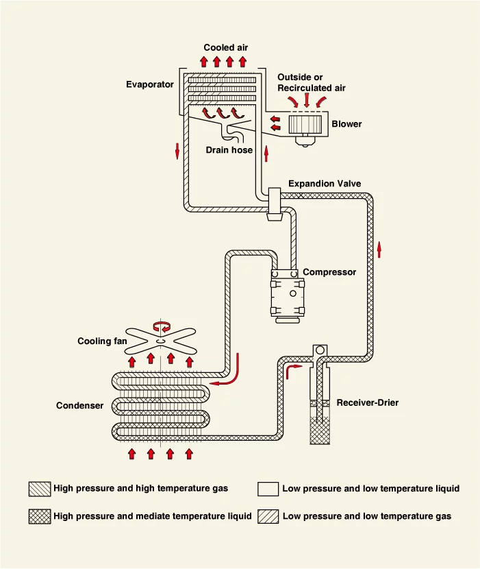
The component of the air conditioner is basically as shown in the figure below. As the refrigerant circulates
between each part, it continuously changes to liquid→gas→liquid, creating a cooling effect.
|
•
|
Evaporator : Atomized refrigerant evaporates into gas while taking heat away
from the
surroundings the action of the blower fan. (The surroundings will be cooled.)
|
|
•
|
Blower : Feeds air in the vehicle under pressure to the evaporator and feeds
cooled air into the
vehicle.
|
|
•
|
Expansion valve : Allows the refrigerant to rapidly expand into low pressure
and low temperature
liquid. (atomized)
|
|
•
|
Compressor : Low pressure (low temperature) gas into high pressure (high
temperature) gas and
supply it to the condenser.
|
|
•
|
Condenser : This is installed in front of the radiator, It cools high pressure
and high
temperature refrigerant to it's condensation point and returns it to high
pressure liquid.
|
|
•
|
Receiver drier : This is a single body type with the condenser and installed at
the side of the
condenser, It stores refrigerant and removes water and foreign material in the
refrigerant.
|
|
Components and Components Location
|
•
|
This video was created using 3D graphics to help understand the vehicle
maintenance manual.
|
|
•
|
There may be some differences from actual vehicles.
|
|
•
|
The location and repair procedures of the parts may vary depending on vehicle
model, model year,
region, and specifications.
|
|
•
|
Check the KDS Guide for detailed information on how to use the KDS.
|
|
•
|
Check the manual for detailed maintenance procedures.
|
|
•
|
Unauthorized reproduction, distribution, or sharing of this video is
prohibited.
|
|
Air Conditioning System Components
(Click to play)
Video: Air Conditioning System Components
1. Condenser
|
7. Compressor
|
2. Radiator
|
8. Evaporator Core
|
3. Expansion Valve
|
9. Blower Motor
|
4. Suction & Liquid Hose Assembly
|
10. Controller
|
5. A/C Pressure Transducer
|
11. PWM-FET
|
6. Discharge Hose
|
|
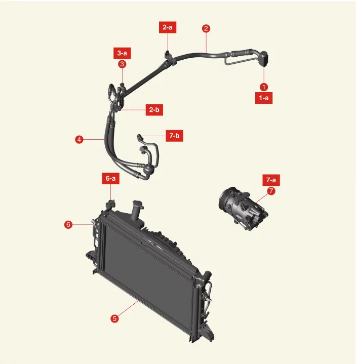
1. Expansion Valve
1-a. 8.8 - 13.7 N·m (0.9
- 1.4
kgf·m, 6.5 - 10.1 lb·ft)
2. Suction & Liquid Hose Assembly
2-a. 7.8 - 11.8 N·m (0.8 - 1.2
kgf·m,
5.8 - 8.7 lb·ft)
2-b. 7.8 - 11.8 N·m (0.8 - 1.2 kgf·m, 5.8 - 8.7 lb·ft)
3. A/C Pressure
Transducer
3-a. 9.8 - 11.8 N·m (1.0 - 1.2 kgf·m, 7.2 - 8.7 lb·ft)
4. Discharge Hose
|
5. Condenser
6. Condenser Pipe
6-a. 21.6
- 32.4
N·m (2.2 - 3.3 kgf·m, 15.9 - 23.9 lb·ft)
7. Compressor
7-a. 19.6 - 33.3 N·m (2.0 - 3.4 kgf·m,
14.5 -
24.6 lb·ft)
7-b. 21.6 - 32.4 N·m (2.2 - 3.3 kgf·m, 15.9 - 23.9 lb·ft)
|
On Vehicle Inspection
| 1.
|
The air conditioning system can be more quickly diagnosed for problems with the KDS (Refer to
"DTC
guide").
| (1)
|
Self diagnosis : Inspect the Diagnostic Trouble Code (DTC) with the KDS.
(Refer to DTC guide when fault code is found)
|
|
Refer to the KDS screen for operating conditions and details.
|
|
A/C Pressure Transducer Description and Operation
Measure the pressure of the refrigerant line and convert it into a voltage value. It optimizes and protects the
air conditioning system by controlling the operation of the compressor using the converted voltage value.
A/C Pressure Transducer Removal and Installation
| 1.
|
Disconnect the battery negative (-) terminal.
|
| 2.
|
Recover the refrigerant with Recovery/Recycling/Charging equipment.
(Refer to Air Conditioning System - "Refrigerant
Recovery/Recycling/Charging/Vacuum/Leak Test")
|
| 3.
|
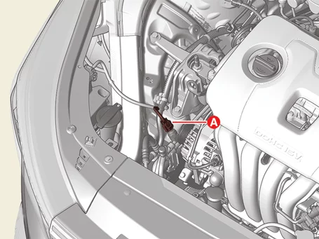
Disconnect the A/C pressure transducer connector (A).
|
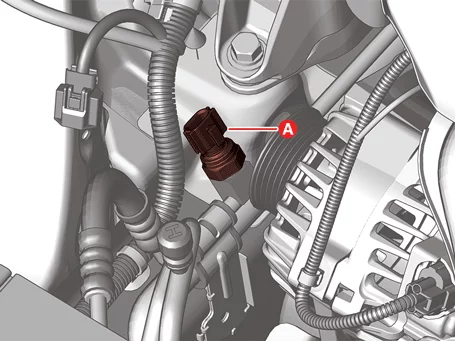
| 4.
|
Remove the transducer (A).
|
Tightening torque:
9.8 - 11.8 N·m (1.0 - 1.2 kgf·m, 7.2 - 8.7 lb·ft)
|
|
| 1.
|
Install in the reverse order of removal.
|
Perform the refrigerant leak test/vacuum/charging by using the refrigerant
recovery/recycling/charging machine.
(Refer to Air Conditioning System -
"Refrigerant
Recovery/Recycling/Charging/Vacuum/Leak Test")
|
|
Ambient Temperature Sensor Specifications
Temperature [°C (°F)]
|
Resistance (kΩ)
|
-40 (-40)
|
811.091 - 956.784
|
-30 (-22)
|
447.670 - 515.428
|
-20 (-4)
|
255.634 - 287.671
|
-10 (14)
|
150.712 - 165.981
|
0 (32)
|
91.533 - 98.775
|
10 (50)
|
57.143 - 60.490
|
20 (68)
|
36.595 - 38.040
|
30 (86)
|
23.795 - 24.729
|
40 (104)
|
15.692 - 16.579
|
50 (122)
|
10.571 - 11.341
|
60 (140)
|
7.263 - 7.907
|
70 (158)
|
5.062 - 5.611
|
80 (176)
|
3.618 - 4.049
|
Ambient Temperature Sensor Description and Operation
|
•
|
It detects the temperature of the air outside the vehicle and converts it into a resistance
value. It is
a negative temperature coefficient (NTC) thermistor type in which the resistance value decreases
when the
temperature rises and the resistance value increases when the temperature decreases.
|
|
•
|
It controls discharge temperature, sensor calibration, temperature control actuator, blower
motor, and
mode control actuator of the heater and air conditioning system.
|
Ambient Temperature Sensor Removal and Installation
|
The indication below represents the location of a clip or fastener.

|
| 1.
|
Remove the front bumper assembly.
(Refer to Body - "Front Bumper Assembly")
|
| 2.
|
Disconnect the ambient temperature sensor connector (A).
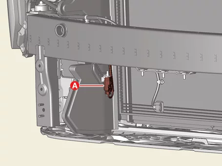
|
| 3.
|
Remove the sensor (A).
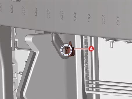
|
| 1.
|
Install in the reverse order of removal.
|
Ambient Temperature Sensor Inspection
| 1.
|
Check whether the resistance values of terminals 1 and 2 change by applying the temperature
change of the
air to the outside temperature sensor.
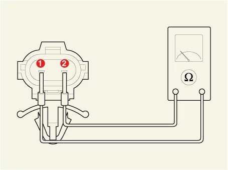
1. Ambient temperature ( +
)
|
2. Sensor Ground
|
Sensor resistance
Temperature [°C
(°F)]
|
Resistance (kΩ)
|
-40 (-40)
|
811.091 - 956.784
|
-30 (-22)
|
447.670 - 515.428
|
-20 (-4)
|
255.634 - 287.671
|
-10 (14)
|
150.712 - 165.981
|
0 (32)
|
91.533 - 98.775
|
10 (50)
|
57.143 - 60.490
|
20 (68)
|
36.595 - 38.040
|
30 (86)
|
23.795 - 24.729
|
40 (104)
|
15.692 - 16.579
|
50 (122)
|
10.571 - 11.341
|
60 (140)
|
7.263 - 7.907
|
70 (158)
|
5.062 - 5.611
|
80 (176)
|
3.618 - 4.049
|
|
Compressor Specifications
Item
|
Specification
|
Type
|
6HVe14
|
Oil type
|
PAG
Kia Approved : FD46XG (IDEMITSU)
|
Capacity [g (oz.)]
|
90 - 110 (3.18 - 3.88)
|
Pulley type
|
6 PK
|
Compressor Description and Operation
The compressor is the power unit of the air conditioning system, mounted on the side of the engine block and
driven by the engine drive belt. The compressor changes the low pressure and low temperature refrigerant to high
pressure and high temperature.
Compressor On Vehicle Inspection
Diagnosis with KDS
| 1.
|
The compressor can be more quickly diagnosed for problems with the KDS (Refer to "DTC guide").
| (1)
|
S/W Management : Controlling other features including system option setting and
zero point
adjustment
(S/W Management → Air conditioning → A/C Compressor Test (ECV Type))
|
•
|
Refer to the KDS screen for operating
conditions and details.
|
|
•
|
The operation type of the compressor is largely
divided into a fixed type
compressor, an internal variable compressor, and
an external variable compressor. In
the case of a fixed type compressor and an
internal variable compressor, the
operation of the compressor can be checked by
the operating sound of the clutch, but
in the case of an external variable compressor,
it is difficult to determine whether
the compressor is operating because there is a
type without a clutch. For this
reason, the external variable compressor is
checked with the inspection procedure
with the KDS.
|
|
|
|
Visual Inspection
| 1.
|
Check for damage to the disc portion of the disc and hub assembly. If there is any damage,
replace the
clutch set.
|
| 2.
|
Check the pulley (A) bearing play / drag by rotating the pulley by hand. Replace the pulley
with a new
one if it is noisy or has excessive play / drag.
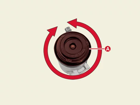
|
Compressor Removal and Installation
|
•
|
This video was created using 3D graphics to help understand the vehicle
maintenance manual.
|
|
•
|
There may be some differences from actual vehicles.
|
|
•
|
The location and repair procedures of the parts may vary depending on vehicle
model, model year,
region, and specifications.
|
|
•
|
Check the KDS Guide for detailed information on how to use the KDS.
|
|
•
|
Check the manual for detailed maintenance procedures.
|
|
•
|
Unauthorized reproduction, distribution, or sharing of this video is
prohibited.
|
|
Compressor Removal
(Click to play)
Video: Compressor Removal
Compressor
|
If the air conditioner is operational, run it for a few minutes.
|
| 1.
|
Disconnect the battery negative (-) terminal.
|
| 2.
|
Recover the refrigerant with Recovery/Recycling/Charging equipment.
(Refer to Air Conditioning System - "Refrigerant
Recovery/Recycling/Charging/Vacuum/Leak Test")
|
| 3.
|
Remove the engine room under cover.
(Refer to Engine Mechanical System - "Engine Room Under
Cover")
|
| 4.
|
Remove the drive belt.
(Refer to Engine Mechanical System - "Drive Belt")
|
| 5.
|
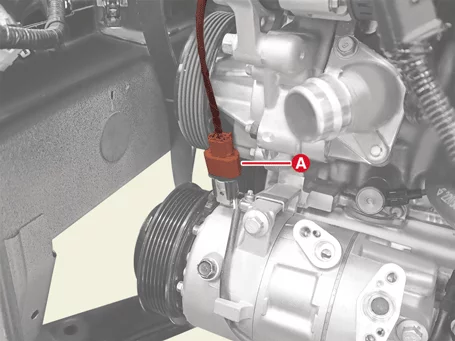
Disconnect the compressor ECV connector (A).
|
| 6.
|
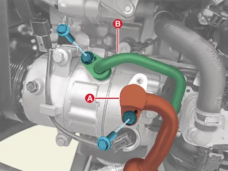
Disconnect the hose (A, B) after removing the bolts.
A : Suction & liquid hose assembly
B : Discharge hose
|
Tightening torque:
21.6 - 32.4 N·m (2.2 - 3.3 kgf·m, 15.9 - 23.9 lb·ft)
|
|
| 7.
|
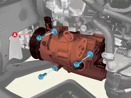
Remove the compressor assembly (A) after removing the bolts.
|
Tightening torque:
19.6 - 33.3 N·m (2.0 - 3.4 kgf·m, 14.5 - 24.6 lb·ft)
|
|
| 1.
|
Install in the reverse order of removal.
|
•
|
Perform the refrigerant leak test/vacuum/charging by using the
refrigerant
recovery/recycling/charging machine.
(Refer to Air Conditioning
System - "Refrigerant
Recovery/Recycling/Charging/Vacuum/Leak Test")
|
|
•
|
Perform the compressor oil inspection.
(Refer to Air Conditioning
System - "Compressor
Oil")
|
|
|
Compressor Disassembly and Reassembly
Tool Name / Number
|
Illustration
|
Description
|
09977 - B9100
Disc & hub assembly bolt stopper
|

|
Removal and installation of disc & hub assembly.
|
| 1.
|
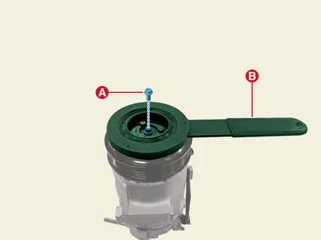
Fix the disk and hub assembly using the air conditioner compressor pulley fixing tool
(09977-3R000) and
removing the bolt (A).
|
Tightening torque:
10.0 - 15.0 N·m (1.02 - 1.53 kgf·m, 7.4 - 11.1 lb·ft)
|
|
| 2.
|
Remove the disc and hub assembly (A).
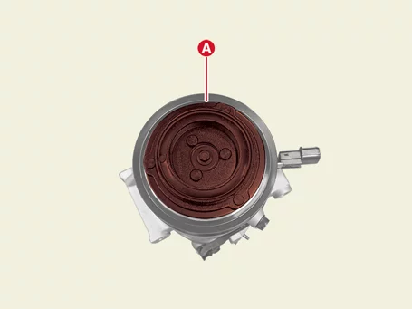
|
| 3.
|
Remove the compressor pulley (A) after removing the snap ring (B).
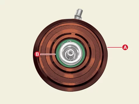
|
•
|
Be careful not to damage the pulley and compressor when
disassembling/assembling.
|
|
•
|
Removed snap rings must be replaced with new ones.
|
|
|
| 4.
|
Disconnect the ECV connector (A).
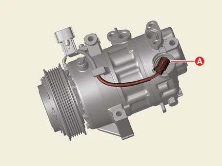
|
| 5.
|
Remove the stator grounding screw (A).
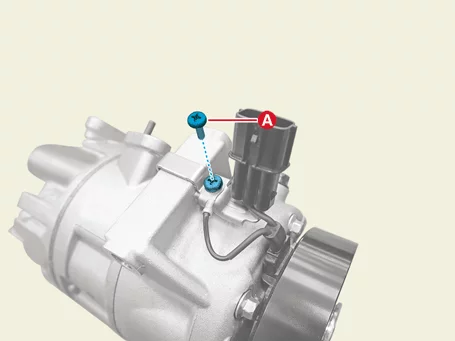
|
| 6.
|
Remove the stator assembly (A) after removing the snap ring (B).
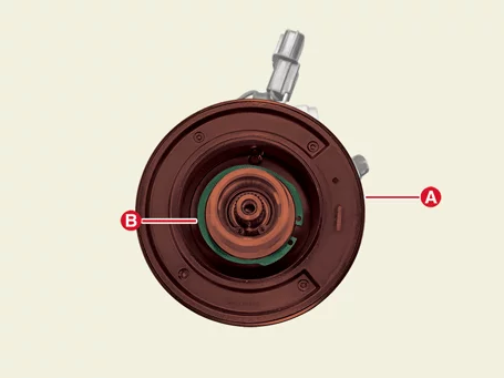
|
•
|
Be careful not to damage the pulley and compressor when
disassembling/assembling.
|
|
•
|
Removed snap rings must be replaced with new ones.
|
|
|
| 1.
|
Reassemble in the reverse order of disassembly.
|
•
|
Make sure that the snap ring is fully seated in the groove
after assembling the snap
ring.
|
|
•
|
Make sure that the pulley rotates smoothly after assembling the
pulley.
|
|
|
Compressor Oil Inspection
|
•
|
Compressor oil is used to lubricate the compressor.
|
|
•
|
Since the oil circulates into the system during the operation of the compressor, the oil must
be
replenished to maintain the total capacity of the original oil when replacing the parts in the
system or
when a large capacity of gas is leaked.
|
|
Total amount of oil in the system : PAG oil 90 - 110 g
(3.18 -
3.88 oz.)
|
|
Kia Approved : FD46XG (IDEMITSU)
|
Compressor Oil Handling Tips
|
•
|
Prevent moisture, dust and metal particles from entering the oil.
|
|
•
|
Do not mix compressor oil.
|
|
•
|
If the oil is left in the air for a long time after using it, the oil absorbs moisture, so be
sure to
close the container immediately after use.
|
Compressor Oil Check and Adjustment
| 1.
|
Oil return operation
| (1)
|
Set to maximum cooling, blower speed, and run the compressor for 20 - 30
minutes to restore oil
to the compressor.
|
|
| 2.
|
Before putting oil into the compressor in use, the compressor oil must be checked in the
following order.
| (1)
|
Turn off the IG after performing the oil return operation.
|
| (2)
|
Recover refrigerant by using the refrigerant recovery/recycling/charging
machine.
(Refer to Air Conditioning System -
"Refrigerant
Recovery/Recycling/Charging/Vacuum/Leak Test")
|
| (3)
|
Remove the compressor.
(Refer to Air Conditioning System -
"Compressor")
|
| (4)
|
Drain the compressor oil.
|
If the drained oil amount is below 70 cc the oil has leaked so
perform a leak test.
(Refer to Air Conditioning
System - "Refrigerant
Recovery/Recycling/Charging/Vacuum/Leak Test")
|
|
| (5)
|
Adjust the oil level after checking the oil for contamination.
Replacement
parts
|
Adjustment
method
|
higher than 70 cc
|
Add the capacity of the oil drained.
|
less than 70 cc
|
Add 70 cc.
|
|
•
|
When exchanging an electric A/C compressor
replenish or drain oil according to
the difference in weight between the old and new
parts before installing it.
|
|
•
|
When the oil in the air conditioning system is
insufficient the durability of the
electric A/C compressor deteriorates.
|
|
•
|
If there is a lot of oil in the air
conditioning system the performance of the
air conditioning system deteriorates.
|
|
|
|
| 3.
|
Oil filling when replacing the parts.
|
•
|
Oil replenishment is performed according to the weight difference between the
old and new parts.
|
Perform oil replenishment by referring to the table below if weight comparison
is not possible.
Replacement
parts
|
Oil amount
cc (oz.)
|
Evaporator Core
|
50 (1.76)
|
Condenser
|
30 (1.06)
|
Receiver drier
|
30 (1.06)
|
Suction & Liquid Hose Assembly
|
10 (0.35)
|
Discharge Hose
|
10 (0.35)
|
|
|
Condenser Removal and Installation
|
The indication below represents the location of a clip or fastener.
|
Condenser
| 1.
|
Recover the refrigerant with Recovery/Recycling/Charging equipment.
(Refer to Air Conditioning System - "Refrigerant
Recovery/Recycling/Charging/Vacuum/Leak Test")
|
| 2.
|
Remove the front bumper beam assembly.
(Refer to Body - "Front Bumper Beam")
|
| 3.
|
Remove the upper air guard (A) after removing the screws.
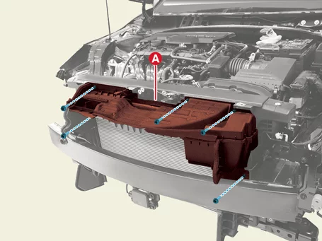
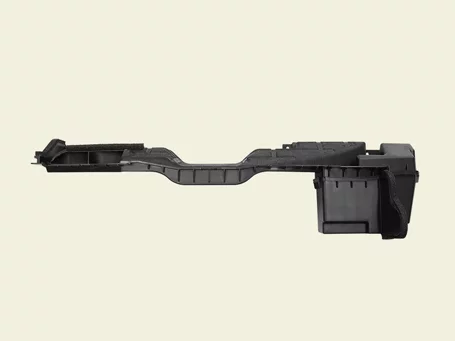
|
| 4.
|
Remove the lower air guard (A) after removing the screws.
Driver's Side
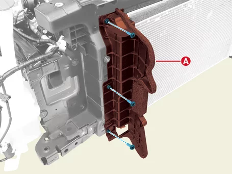
Passenger's Side
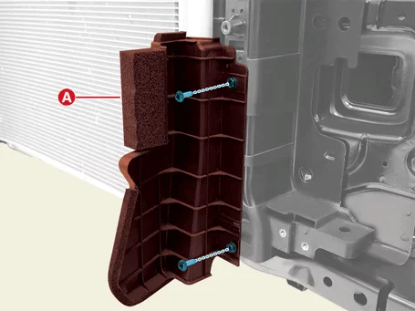
|
| 5.
|
Disconnect the hoses (A, B) after removing the nuts.
A : Suction & liquid hose assembly
B : Discharge hose
|
Tightening torque:
21.6 - 32.4 N·m (2.2 - 3.3 kgf·m, 15.9 - 23.9 lb·ft)
|
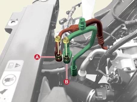
|
| 6.
|
Remove the condenser (A).
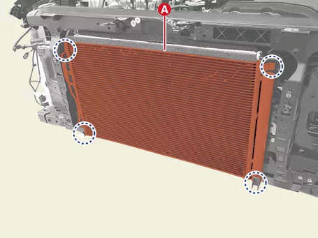
|
| 1.
|
Install in the reverse order of removal.
|
•
|
Perform the refrigerant leak test/vacuum/charging by using the
refrigerant
recovery/recycling/charging machine.
(Refer to Air Conditioning
System - "Refrigerant
Recovery/Recycling/Charging/Vacuum/Leak Test")
|
|
•
|
Perform the compressor oil inspection.
(Refer to Air Conditioning
System - "Compressor
Oil")
|
|
|
Evaporator Temperature Sensor Specifications
Temperature [°C (°F)]
|
Resistance (kΩ)
|
-10 (14)
|
42.73 - 43.98
|
0 (32)
|
27.35 - 27.89
|
10 (50)
|
17.82 - 18.32
|
20 (68)
|
11.89 - 12.33
|
30 (86)
|
8.124 - 8.845
|
40 (104)
|
5.666 - 5.960
|
Evaporator Temperature Sensor Description and Operation
|
•
|
The temperature of the evaporator core is sensed and converted into a resistance value. It is a
negative
temperature coefficient (NTC) thermistor type in which the resistance value decreases when the
temperature
rises and the resistance value increases when the temperature decreases.
|
|
•
|
Prevents freezing of the evaporator core when using the air conditioner for a long time.
|
|
–
|
When the temperature of the evaporator core is below about 0.5 - 1.5 (32.9 - 34.7) °C (°F), the
air
conditioner relay output power is cut off to stop the operation of the compressor.
|
|
–
|
When the temperature of the evaporator core reaches about 3.0 - 4.0 (37.4 - 39.2) °C (°F), the
air
conditioner relay operates to operate the compressor.
|
Evaporator Temperature Sensor Removal and Installation
| 1.
|
Remove the evaporator core.
(Refer to Heater - "Evaporator Core")
|
| 2.
|
Remove the evaporator temperature sensor (A).
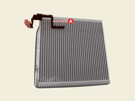
|
| 1.
|
Install in the reverse order of removal.
|
Evaporator Temperature Sensor Inspection
| 3.
|
Measure the resistance of the evaporator temperature sensor 1 - 2 terminal.
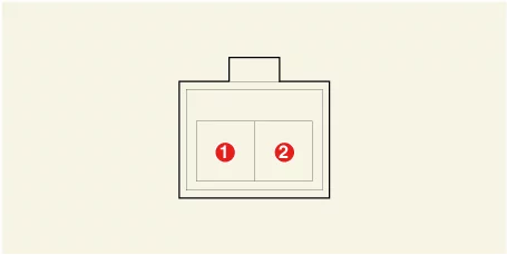
1. Sensor Ground
|
2. Evaporator Sensor ( + )
|
Temperature [°C
(°F)]
|
Resistance (kΩ)
|
-10 (14)
|
42.73 - 43.98
|
0 (32)
|
27.35 - 27.89
|
10 (50)
|
17.82 - 18.32
|
20 (68)
|
11.89 - 12.33
|
30 (86)
|
8.124 - 8.845
|
40 (104)
|
5.666 - 5.960
|
|
In-car Sensor Description and Operation
|
•
|
It detects the air temperature inside the vehicle and converts it into a resistance value. It
is a
negative characteristic (NTC) thermistor type in which the resistance value decreases when the
temperature
rises and the resistance value increases when the temperature decreases.
|
|
•
|
It controls discharge temperature, sensor calibration, temperature control actuator, blower
motor, and
mode control actuator of the heater and air conditioning system.
|
In-car Sensor Removal and Installation
|
The indication below represents the location of a clip or fastener.
|
| 1.
|
Remove the crash pad air vent. [Passenger's side]
(Refer to Body - "Crash Pad Air Vent")
|
| 2.
|
Remove the in-car sensor (A).
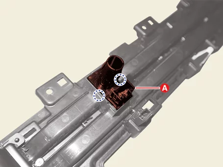
|
| 1.
|
Install in the reverse order of removal.
|
Photo Sensor Description and Operation
It detects changes in the brightness of the surrounding environment and converts them into voltage values. The
air volume and discharge temperature of the heater and air conditioner system is controlled using the converted
voltage value.
Photo Sensor Removal and Installation
|
The indication below represents the location of a clip or fastener.
|
| 1.
|
Remove the center speaker grille.
(Refer to Body - "Crash Pad Cover")
|
| 2.
|
Remove the photo sensor (A).
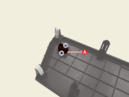
|
| 1.
|
Install in the reverse order of removal.
|
Receiver-Drier Removal and Installation
| 1.
|
Remove the condenser.
(Refer to Air Conditioning System - "Condenser")
|
| 2.
|
Remove the receiver drier cap (A).
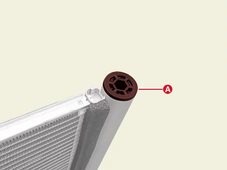
|
| 3.
|
Remove the receiver drier filter (A) and O-ring (B).
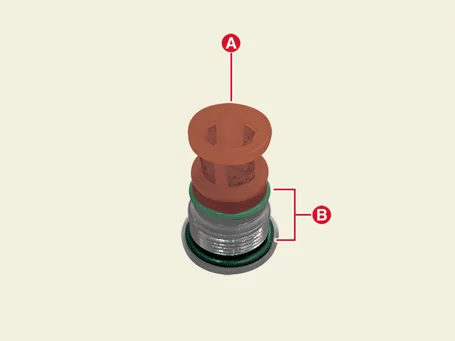
|
| 4.
|
Remove the desiccant (A).
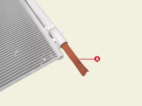
|
| 1.
|
Install in the reverse order of removal.
|
•
|
Perform the refrigerant leak test/vacuum/charging by using the
refrigerant
recovery/recycling/charging machine.
(Refer to Air Conditioning
System - "Refrigerant
Recovery/Recycling/Charging/Vacuum/Leak Test")
|
|
•
|
Perform the compressor oil inspection.
(Refer to Air Conditioning
System - "Compressor
Oil")
|
|
|
Refrigerant Line Specifications
Item
|
Specification
|
Refrigerant
|
Type
|
R - 1234yf
|
R - 134a
|
Capacity [g (oz.)]
|
475 - 525 (16.76 - 18.52)
|
525 - 575 (18.52 - 20.28)
|
Refrigerant Line Removal and Installation
Suction & Liquid Hose Assembly
|
If the air conditioner is operational, run it for a few minutes.
|
| 1.
|
Recover the refrigerant with Recovery/Recycling/Charging equipment.
(Refer to Air Conditioning System - "Refrigerant
Recovery/Recycling/Charging/Vacuum/Leak Test")
|
| 2.
|
Remove the front bumper assembly.
(Refer to Body - "Front Bumper Assembly")
|
| 3.
|
Remove the engine mounting bracket.
(Refer to Engine Mechanical System - "Engine Mounting")
|
| 4.
|
Disconnect the A/C pressure transducer connector (A).
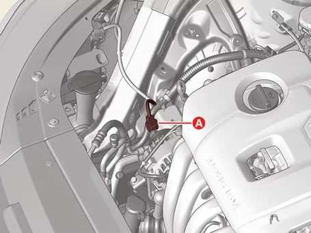
|
| 5.
|
Separate the suction & liquid hose assembly (A) after removing the nut.
|
Tightening torque:
21.6 - 32.4 N·m (2.2 - 3.3 kgf·m, 15.9 - 23.9 lb·ft)
|
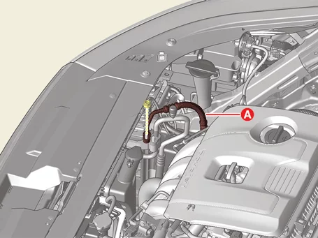
|
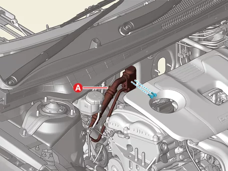
| 6.
|
Separate the expansion valve (A) after removing the bolts.
|
Tightening torque:
8.8 - 13.7 N·m (0.9 - 1.4 kgf·m, 6.5 - 10.1 lb·ft)
|
|
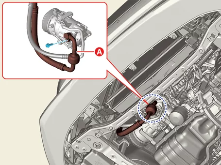
| 7.
|
Separate the suction & liquid hose assembly (A) after removing the bolt.
|
Tightening torque:
21.6 - 32.4 N·m (2.2 - 3.3 kgf·m, 15.9 - 23.9 lb·ft)
|
|
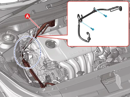
| 8.
|
Remove the suction & liquid hose assembly (A) after removing the bolts.
|
Tightening torque:
7.8 - 11.8 N·m (0.8 - 1.2 kgf·m, 5.8 - 8.7 lb·ft)
|
|
Discharge Hose
|
If the air conditioner is operational, run it for a few minutes.
|
| 1.
|
Recover the refrigerant with Recovery/Recycling/Charging equipment.
(Refer to Air Conditioning System - "Refrigerant
Recovery/Recycling/Charging/Vacuum/Leak Test")
|
| 2.
|
Remove the engine room under cover.
(Refer to Engine Mechanical System - "Engine Room Under
Cover")
|
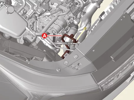
| 3.
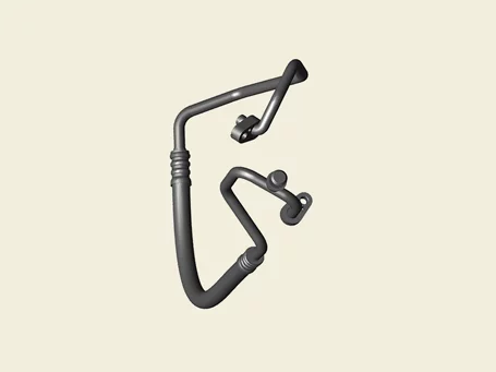
|
Remove the discharge hose (A) after removing the bolt and nut.
|
Tightening torque:
21.6 - 32.4 N·m (2.2 - 3.3 kgf·m, 15.9 - 23.9 lb·ft)
|
|
| 1.
|
Install in the reverse order of removal.
|
•
|
Perform the refrigerant leak test/vacuum/charging by using the
refrigerant
recovery/recycling/charging machine.
(Refer to Air Conditioning
System - "Refrigerant
Recovery/Recycling/Charging/Vacuum/Leak Test")
|
|
•
|
Perform the compressor oil inspection.
(Refer to Air Conditioning
System - "Compressor
Oil")
|
|
|
Other information:
Kia K4 (CL4) 2025-2026 Service Manual: Wireless smartphone charging system
The Kia K4 features an advanced wireless smartphone charging system conveniently located at the front of the center console, allowing you to power your mobile devices without the clutter of cables.
Charging indicator light
Wireless charging pad surface
To ensure proper operation, firmly close all vehicle doors and start the Kia K4 engine or set the ignition to the ON position.
Kia K4 (CL4) 2025-2026 Service Manual: LCD display messages
Door, hood, liftgate, or sunroof open
For your safety, the Kia K4 LCD display provides an immediate warning if a door, the hood, the rear liftgate, or the sunroof is not securely closed.