Contents:
Description and Operation
|
•
|
Wheel alignment is all forces due to friction, gravity, centrifugal force and inertia operate
in a
balanced manner while driving.
|
|
•
|
Wheel alignment improves linearity, grounding performance, tire life extension and fuel
reduction and
ensures safety at high speeds.
|
|
•
|
Alignment adjustments consist of camber, castor, kingpin angle, toe, left, thrust angle, etc.
|
Camber
Camber refers to the angle at which the top of the wheel is tilted inward or outward relative to the vertical
line started from the center of the floor when the vehicle is viewed from the front.
|
–
|
It facilitates steering control of the steering wheel and prevents bending of the front axle.
|
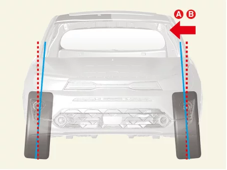
[Plus ( + ) Camber]
It is a camber form with wheels tilted outward from the top. It prevents the underside of the wheel from
opening,
so there is less tire wear due to unnecessary driving resistance on curves.
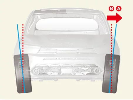
[Minus (-) Camber]
It is a camber form with wheels tilted inward from the top. cause strong friction when driving curves but tires
are prone to wear.
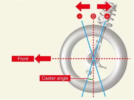
Caster
Caster refers to the angle at which the steering shaft tilts forward and backward relative to the vertical line
initiated from the center of the wheel floor when the vehicle is viewed from the side.
|
–
|
It gives a straight line to the steering wheel when driving.
|
|
–
|
Provides resilience to wheels when steering.
|
|
–
|
It prevents shaking of wheels while driving.
|
King pin angle
Kingpin angle refers to the angle at which the centerline of the steering shaft and the bottom vertical line
forms when the vehicle is viewed from the front.
|
–
|
Provides easy steering of the steering wheel and resilience of the steering wheel.
|
|
–
|
The kingpin angle and camber are also called Included Angle (I.A.). [Included Angle (I.A.)]
|
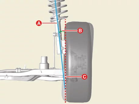
Item
|
Descriptions
|
A
|
Steering Center Line
|
B
|
Kingpin
|
C
|
Center Line
|
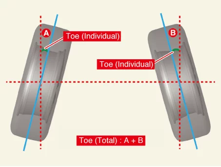
Toe
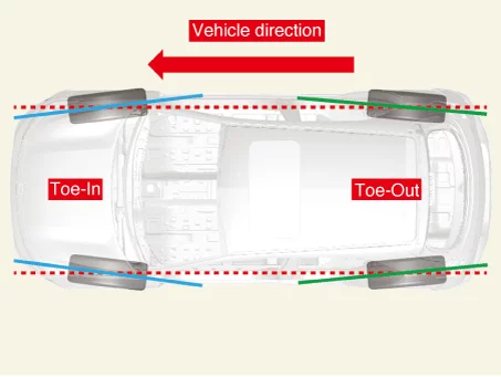
Toe is the tilted angle or distance at the front of the wheel when looking up and down at the vehicle.
|
–
|
The state in which the front of the wheel faces outward is called Toe out, and the state in
which the
front of the wheel faces inward is called Toe in.
|
|
–
|
In general vehicles, toe-in is applied to prevent side slip.
A phenomenon in which the wheels slide sideways due to the influence of the camber while the
vehicle is
driving.
|
|
–
|
Tow-out is sometimes applied to vehicles that require a fast steering response when turning.
|
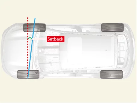
Setback
Setback refers to the angle at which the line connects the center of the front wheels from the vehicle's
centerline.
|
–
|
The main cause of the setback is the presence of an accident in the vehicle or an abnormality
in the
body.
|
Thrust Angle
The angle at which the thrust line and the centerline of the vehicle are formed.
※Thrust line: A line that is perpendicular to the center line of the vehicle and the center line of the rear
axle.
|
–
|
Thrust conditions occur when the rear wheel individual toe is not the same.
|
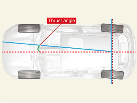
|
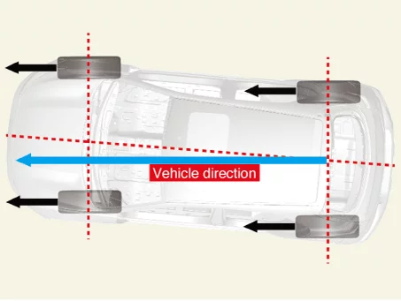
Poor thrust angles can increase tire wear, reduce steering direction, and cause dog tracking.
※Dog tracking: The driving condition when the thrust line is not parallel to the center line of
the
vehicle
|
On Vehicle Inspection
Driving test
Carry out pre-work vehicle driving tests to check vehicle behavior under normal driving conditions.
| 1) |
Check that the vehicle is going straight when release the steering wheel.
|
| 2) |
Check that the vehicle pulls to one side while accelerating and braking.
|
| 1) |
Check the vehicle pulls to one side while braking.
|
| 2) |
Check that the vehicle pulls to one side while accelerating or decelerating.
|
| 3) |
Check the part for noise or abnormal movement.
|
| 1) |
Turn the steering wheel and check if it returns when released.
|
| 2) |
Check if the vehicle is pulls in the direction in which the steering wheel was last turned.
|
| 3) |
Check the part for noise or abnormal movement.
|
| Deflected or protruded road |
| 1) |
Check if the vehicle changes direction.
|
| 2) |
Check the part for noise or abnormal movement.
|
| 3) |
Check if the vehicle is over-bouncing.
|
Tire Wear Inspection
Wheel and tire diagnosis
|
Rapid wear at the center
|
Rapid wear at both shoulders
|
Wear at one shoulder
|
|
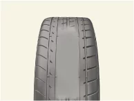
|
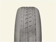
|
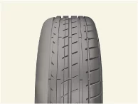
|
|
•
|
Poor installing of tire
|
|
•
|
Excessive rapid acceleration
|
|
|
•
|
Poor installing of tire
|
|
•
|
Too low amount of tire air pressure
|
|
•
|
Damaged suspension components
|
|
•
|
Excessive cornering speeds
|
|
|
•
|
Too low amount of tire air pressure
|
|
•
|
Camber out of specification
|
|
•
|
Damaged suspension components
|
|
Partial wear
|
Feathered edge
|
Diagonal wear
|
|
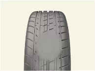
|
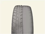
|
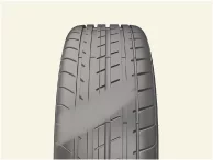
|
|
•
|
Damaged or worn brake discs
|
|
•
|
Excessive sudden acceleration, sudden braking
|
|
•
|
Damaged suspension components
|
|
•
|
Too low amount of tire air pressure
|
|
|
|
•
|
Camber out of specification
|
|
•
|
Damaged suspension components
|
|
Inspect steering system related parts
| 1) |
Check the universal joint for tightening, wear, damage and rust.
|
| 2) |
Check that the mounting is loose by moving the steering gearbox up and down, and if damaged,
replace it.
|
| 3) |
Check the steering gearbox housing for abnormalities.
|
Inspect suspension system related parts
| 1) |
Check each suspension bushing for wear, cracks, etc.
|
| 2) |
Check the strut and shock absorber for damage.
|
| 3) |
Check the ride height.
|
| 4) |
Check the coil spring for damage or wear.
|
| 5) |
Check the lower arm ball joint for damage or free play.
|
Repair Procedures
| Wheel Alignment Repair Procedures |
| 1.
|
When using the wheel alignment tester to check the wheel alignment, align the lift's vehicles
horizontally.
|
| 2.
|
Set the transmission gear to 'N'.
|
| 3.
|
Inflate the 4 tires to the specified tire pressure.
Tire Size
|
Tire Pressure [kPa (psi)]
|
Front
|
Rear
|
205/55 R16
|
Steel wheel
|
250 (36)
|
230 (33)
|
Aluminum wheel
|
235 (34)
|
215 (31)
|
225/45 R17
|
235/40 R18
|
230 (33)
|
|
| 4.
|
Check the steering wheel and tires aligning straight.
|
| 5.
|
Hold the brake pedal depressed using a pedal stopper.
|
| 6.
|
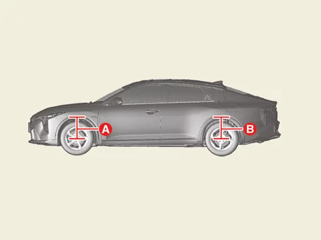
Measure the ride height, which is the distance from the end of the fender to the center of the
wheel.
Ride Height [mm (in.)]
Couple Torsion Beam Axle Type
|
Front (A) : 367 ± 10 (14.44 ± 0.39)
Rear (B) : 367 ± 10 (14.44 ± 0.39)
|
Multi-link Type
|
Front (A) : 367 ± 10 (14.44 ± 0.39)
Rear (B) : 362 ± 10 (14.25 ± 0.39)
|
Multi-link Type [GT-line]
|
Front (A) : 362 ± 10 (14.25 ± 0.39)
Rear (B) : 362 ± 10 (14.25 ± 0.39)
|
|
| 7.
|
Adjust the alignment to the specification.
(Refer to Alignment - "Adjustment")
|
It is not recommended to adjust the rear alignment of the coupled torsion beam
axle using an
adjustment shim or washer. Vehicle performance may be poor.
|
|
| 8.
|
After adjusting, shake the vehicle and check if the alignment value returns.
|
If the value changes significantly, check the suspension for free play or
bushing damage and
wear.
|
|
| 9.
|
Perform in the order below with the KDS.
(S/W Management → EPS - Power Steering → SAS Calibration)
|
Refer to the KDS screen for operating conditions and details
|
|
Adjustment
[Rear - Coupled Torsion Beam Axle]
If the rear alignment exceeds the reference value, replace the rear torsion beam axle with a new one.
|
It is not recommended to adjust the rear alignment of the coupled torsion beam axle type using
an
adjustment shim or washer. Vehicle performance may be poor.
|
(Refer to Rear Suspension System - "Rear Torsion Beam Axle")
|
Total Toe : 0.32 ± 0.3 °
Individual Toe : 0.16 ± 0.15 °
|
|
Camber Angle : -1.2 ± 0.5 °
|
|
Thrust Angle : 0.0 ± 0.15 °
|
[Rear - Multi-link]
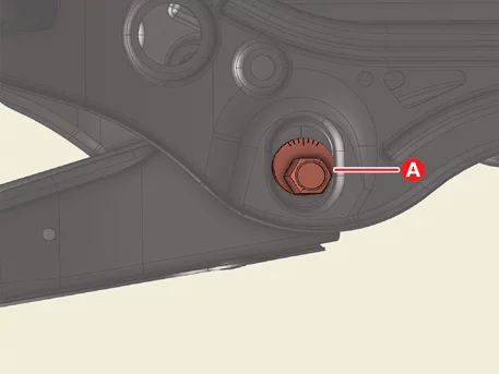
Turn the cam bolt (A) attached with the rear assist arm clockwise or counterclockwise to adjust the toe. Adjust
the left and right cam bolts to the same amount.
|
Total : 0.14 ± 0.2 °
Individual : 0.07 ± 0.1 °
|
Cam
|
Rotation
|
Increae and Decrease
|
Change (°)
|
RH
|
Clockwise
|
Toe in
|
Toe about 0.32
Camber about 0.22
*Per
scale
|
LH
|
Clockwise
|
Toe out
|
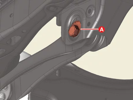
|
Adjust the toe using total toe.
|
Turn the cam bolts (A) attached with the rear lower arm clockwise or counterclockwise to adjust the camber.
|
Camber Angle : -1.2 ± 0.5 °
|
Cam
|
Rotation
|
Increae and Decrease
|
Change (°)
|
RH
|
Clockwise
|
+ Camber
|
Toe about 0.31
Camber about 0.05
*Per
scale
|
LH
|
Clockwise
|
- Camber
|
|
Thrust Angle : 0.0 ± 0.05 °
|
[Front]
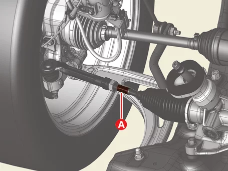
Toe is adjusted by rotation of the tie rod rotation buckle. Turning the tie rod to the rear of the vehicle will
reduce the toe on the front wheels. The adjustment toe is adjusted by turning the left and right tie rods to the
same value.
|
Total : 0.1 ± 0.2 °
Individual : 0.05 ± 0.1 °
|
| 1.
|
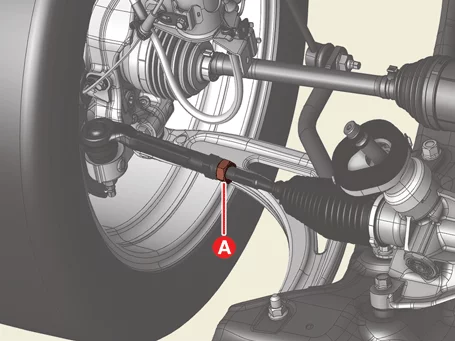
Loosen the tie rod end nut (A) until the toe can be adjusted.
|
Tightening torque :
49.0 - 53.9 N·m (5.0 - 5.5 kgf·m, 36.2 - 39.8 lb·ft)
|
|
| 2.
|
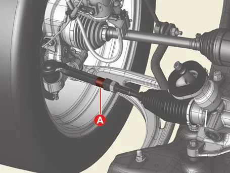
Fix the tie rod end (A) using a wrench to prevent the tie rod from turning when adjusting
alignment.
|
| 3.
|
Adjust the toe in the specified value by turning the tie rod turn buckle (A).
|
After toe adjustment, match the remaining number of threads on the left and
right equally.
|
|
| 4.
|
After adjustment, tighten the tie rod end nut (A) to specification torque.
|
Tightening torque :
49.0 - 53.9 N·m (5.0 - 5.5 kgf·m, 36.2 - 39.8 lb·ft)
|
|
|
•
|
Be careful not to twist the bellows boot when adjusting the toe.
|
|
•
|
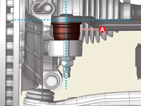
After toe adjustment, adjust the tie rod end position horizontally to ensure
that the ball joint
boot (A) is not pressed.
|
|
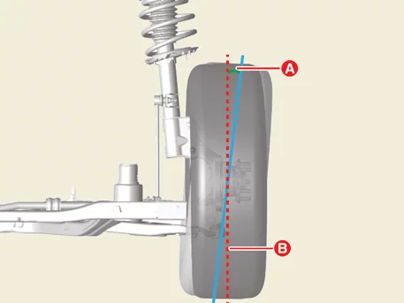
The camber cannot be adjusted. If the measured camber exceeds the standard limit, repair or replace the
relevant
parts and inspect the wheel alignment again.
|
Camber Angle : -0.6 ± 0.5 °
|
Item
|
Description
|
A
|
Camber Angle
|
B
|
Center Line
|
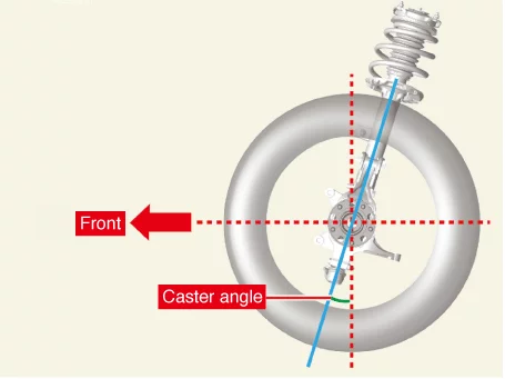
The caster cannot be adjusted. If the measured caster exceeds the standard limit, repair or replace the
relevant
parts and inspect the wheel alignment again.
|
Caster Angle
Standard : 4.6 ± 0.5 °
GT-line : 4.8 ± 0.5 °
|
|
•
|
Before measuring the front wheel alignment, wear, loose and damaged parts of
the front suspension
assembly should be replaced.
|
|
•
|
Camber and caster are assembled at the specified value during production and
need not be
adjusted.
|
|
•
|
If the camber and caster are not within the specified limits, replace the bent
or damaged parts.
|
|
•
|
The difference between the left and right wheels of Camber and Caster shall be
within 0° ± 0.5°.
|
|
The king pin angle cannot be adjusted. If the measured caster exceeds the standard limit, repair or replace the
relevant parts and inspect the wheel alignment again.
|
Kingpin Angle
Standard : 14.5 ± 0.5 °
GT-line : 14.7 ± 0.5 °
|
Item
|
Description
|
A
|
Steering Center Line
|
B
|
Kingpin
|
C
|
Center Line
|
Setback cannot be adjusted, but the value is useful for diagnosing central steering problems, such as tilting.
After repairing a vehicle with a damaged frame, the setback must be checked. The ideal setback value should be
zero.
Other information:
Kia K4 (CL4) 2025-2026 Service Manual: Theft-alarm system
The integrated factory theft-alarm system engineered for your vehicle provides robust perimeter protection against unauthorized entry, forced break-ins, and potential vehicle theft. By continuously monitoring structural entry sensors, this security framework shields your vehicle from criminal intent and alerts bystanders in the event of a security breach.
Kia K4 (CL4) 2025-2026 Service Manual: Tires and wheels
For consistent vehicle performance, long-term safety, and optimal fuel economy, it is essential that you always maintain the recommended tire pressures and operate the Kia K4 within the specified load limits and weight distribution guidelines.
Recommended cold tire inflation pressures
For the most accurate readings, check all tire pressures while the tires are "cold.