Electrical Specified Value Inspection (Using the Voltmeter and
Ammeter)
| 1.
|
Voltage drop test of alternator output wire
This test is to check the wiring condition between the alternator B terminal and the battery (
+ )
terminal by using the voltage drop of the wiring.
| (1)
|
Preparation
| b. |
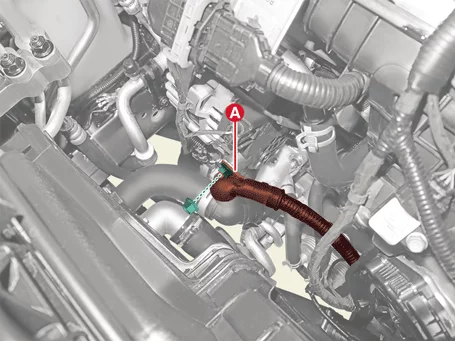
Remove the alternator B terminal cable (A) after opening the
cover and removing the nut.
|
Tightening
torque :
18.6 - 24.5 N·m (1.9 - 2.5 kgf·m, 13.7 - 18.1
lb·ft)
|
|
| c. |
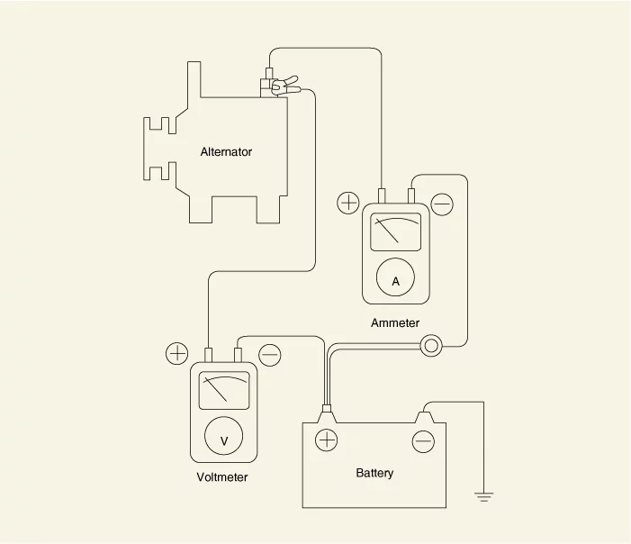
Connect the ( + ) lead wire of the DC ammeter into the
alternator B terminal and the ( -
) lead wire into the disconnected output wiring in series.
Connect ( + ) lead wire of the
digital voltmeter into the alternator B terminal and ( - ) lead
wire into ( + ) terminal of
the battery.
|
|
| (2)
|
Test
| b. |
Check the value displayed by the voltmeter when the ammeter
indicates 30 A by operating
the headlamp, blower motor, etc., and adjusting the engine
speed.
|
|
| (3)
|
Result
| a. |
It is normal if the measured value of the voltmeter is below
the specified value.
|
Specified value
(V) : Maximum 0.2
|
|
| b. |
If the value of the voltmeter is higher than standard value,
defective wiring is
suspected. In this case check the wiring from the alternator B
terminal to the fuse and
battery ( + ) terminal. Check for wiring connection,
discoloration by over-heated harness,
etc. Correct them before testing again.
|
|
|
| 2.
|
Output Current Test
This test is to verify that the output current of the alternator matches the rated current.
| (1)
|
Preparation
| a. |
Check the following items and repair if necessary before the
test.
• Check that the battery is in good condition.
(Refer to Charging System -
"Battery")
• The battery that is used in the output current test should
not be fully charged.
• The fully charged battery is unsuitable for testing due to
insufficient load.
• Check the tension and condition of the alternator drive belt.
|
| c. |
Disconnect the battery negative ( - ) terminal.
|
| d. |
Remove the alternator B terminal cable (A) after opening the
cover and removing the nut.
|
Tightening
torque :
18.6 - 24.5 N·m (1.9 - 2.5 kgf·m, 13.7 - 18.1
lb·ft)
|
|
| e. |
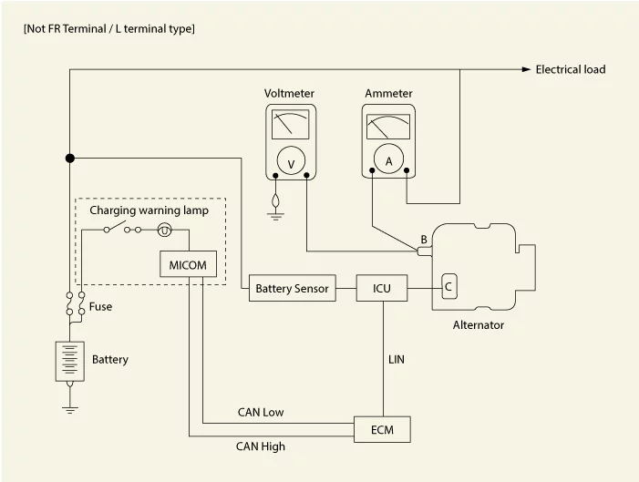
Connect a ( + ) lead wire of DC ammeter(0 to 150 A) to the
alternator B terminal and ( -
) lead wire to disconnected output wiring in series.
|
•
|
Since high currents flow,
tighten and insulate each
connecting parts
properly.
|
|
•
|
Do not use clip, etc.
|
|
|
| f. |
Connect a ( + ) lead wire of digital voltmeter (0 - 20 V) to B
terminal of alternator and
( - ) lead wire to ground.
|
| g. |
Install the engine tachometer and connect the battery ground
cable.
|
| h. |
Leave the engine hood open.
|
|
| (2)
|
Test
| a. |
Check that the value indicated by the voltmeter is the same as
the battery voltage. If
the voltmeter indicates 0 V, suspect an open circuit or poor
grounding between the
alternator B terminal and the battery ( + ) terminal.
|
| b. |
Start the engine and turn on the headlamp.
|
| c. |
Set the headlamp to high beam and the heater blower switch to
maximum, quickly increase
the engine speed to 2,500 rpm and read the maximum output
current indicated by the ammeter.
|
•
|
Since the charging current
rapidly decreases after starting
the engine so
the maximum output current value
must be read quickly and
accurately.
|
|
•
|
If the battery discharges which
is used in the measuring
instrument, the
measured value drops, so make
sure to check the battery
status.
|
|
•
|
When measuring current, the
vehicle's electrical load must
be applied to
measure the current accurately.
|
|
|
|
| (3)
|
Result
| a. |
The ammeter must display over the limit value. If the output
line of the alternator is in
good condition but displays less than the limit value, remove
the alternator from the
vehicle and test.
|
Limit value (%)
: 60 of the voltage rate
|
|
•
|
Since the output voltage
changes due to the electrical
load and the
temperature of the alternator
itself, the rated current may
not be measured.
In this case, turning on the
headlamp to discharge the
battery or using the
headlamp of other vehicle may
increase the electrical load.
|
|
•
|
If the rated current cannot be
obtained due to the temperature
of the
alternator itself or excessively
high ambient temperature, reduce
the
temperature and retest.
|
|
|
The rated current value is marked on the
nameplate on the back of the alternator
unit.
|
|
|
|
| 3.
|
Regulated Voltage Test
The purpose of this test is to check that the electronic voltage regulator controls voltage
properly.
| (1)
|
Preparation
| a. |
Check the following items and repair if necessary before the
test.
• Check that the battery is in good condition.
(Refer to Charging System -
"Battery")
• The battery to be used for the regulated voltage test must be
a fully charged battery.
|
| c. |
Disconnect the battery negative ( - ) terminal.
|
| d. |
Connect the ( + ) lead of the voltmeter to the alternator B
terminal and the ( - ) lead
to the ground or battery ( - ) terminal.
|
| e. |
Remove the alternator B terminal cable (A) after opening the
cover and removing the nut.
|
Tightening
torque :
18.6 - 24.5 N·m (1.9 - 2.5 kgf·m, 13.7 - 18.1
lb·ft)
|
|
| f. |
Connect a ( + ) lead wire of DC ammeter (0 to 150 A) to B
terminal of alternator and ( -
) lead wire to disconnected output wire in serial.
|
| g. |
Connect the battery negative ( - ) terminal.
|
|
| (2)
|
Test
| a. |
Turn the IG ON and check if the voltmeter displays the
following values.
|
Voltage
: Battery voltage
|
If 0 V is displayed, suspects an open circuit or a faulty
ground between the alternator B
terminal and the battery ( - ) terminal.
|
| b. |
Start the engine and keep all lights and accessories off.
|
| c. |
Adjust the engine speed to 2,500 rpm and read the value
indicated by the voltmeter when
the alternator output current drops below 30 A.
|
|
| (3)
|
Result
| a. |
If the value indicated by the voltmeter matches the regulated
voltage value, the voltage
regulator operates normally, and if it is different from the
specified value, the regulator
or alternator is defective.
|
Regulated
voltage (V) : 10.6 - 16.0
|
|
|
|
Electrical Specified Value Inspection (Using the Voltmeter and Clamp
type Ammeter)
| 1.
|
Voltage drop test of alternator output wire
This test is to check the wiring condition between the alternator B terminal and the battery (
+ )
terminal by using the voltage drop of the wiring.
| (1)
|
Preparation
| b. |
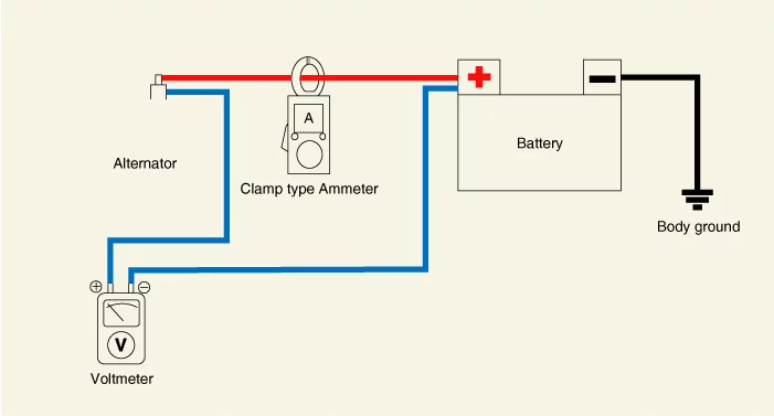
Install the clamp type ammeter between battery positive ( + )
and alternator B terminal.
|
When measuring, if "( - )" is displayed on the
screen, the direction is reversed.
|
|
| c. |
Connect the ( + ) lead wire of the voltmeter to the alternator
B terminal and the ( - )
lead wire to the battery ( + ) terminal.
|
|
| (2)
|
Test
| b. |
Check the value displayed by the voltmeter when the ammeter
indicates 30 A by operating
the headlamp, blower motor, etc., and adjusting the engine
speed.
|
|
| (3)
|
Result
| a. |
It is normal if the measured value of the voltmeter is below
the specified value.
|
Specified value
(V) : Maximum 0.2
|
|
| b. |
If the value of the voltmeter is higher than standard value,
defective wiring is
suspected. In this case check the wiring from the alternator B
terminal to the fuse and
battery ( + ) terminal. Check for wiring connection,
discoloration by over-heated harness,
etc. Correct them before testing again.
|
|
|
| 2.
|
Output current test
This test is to verify that the output current of the alternator matches the rated current.
| (1)
|
Preparation
| a. |
Check the following items and repair if necessary before the
test.
• Check that the battery is in good condition.
(Refer to Charging System -
"Battery")
• The fully charged battery is unsuitable for testing due to
insufficient load.
• Check the tension and condition of the alternator drive belt.
|
| c. |
Disconnect the battery negative ( - ) terminal.
|
| d. |
Install the clamp type ammeter between battery positive ( + )
and alternator B terminal.
|
When measuring, if "( - )" is displayed on the
screen, the direction is reversed.
|
|
| e. |
Connect the ( + ) lead wire of the voltmeter to the alternator
B terminal and the ( - )
lead wire to the battery ( + ) terminal.
|
•
|
Since high currents flow,
tighten and insulate each
connecting parts
properly.
|
|
•
|
Do not use clip, etc.
|
|
|
| f. |
Connect the battery negative ( - ) terminal.
|
| g. |
Leave the engine hood open.
|
|
| (2)
|
Test
| a. |
Check that the value indicated by the voltmeter is the same as
the battery voltage. If
the voltmeter indicates 0 V, suspect an open circuit or poor
grounding between the
alternator B terminal and the battery ( + ) terminal.
|
| b. |
Start the engine and turn on the headlamp.
|
| c. |
Set the headlamp to high beam and the heater blower switch to
MAX, quickly increase the
engine speed to 2,500 rpm and read the maximum output current
indicated by the ammeter.
|
•
|
Since the charging current
rapidly decreases after starting
the engine so
the maximum output current value
must be read quickly and
accurately.
|
|
•
|
If the battery discharges which
is used in the measuring
instrument, the
measured value drops, so make
sure to check the battery
status.
|
|
•
|
When measuring current, the
vehicle's electrical load must
be applied to
measure the current accurately.
|
|
|
|
| (3)
|
Result
| a. |
The ammeter must display over the limit value. If the output
line of the alternator is in
good condition but displays less than the limit value, remove
the alternator from the
vehicle and test.
|
Limit value (%)
: 60 of the voltage rate
|
|
•
|
Since the output current
changes due to the electrical
load and the
temperature of the alternator
itself, the rated current may
not be obtained.
In this case, the electric load
can be increased by turning on
the headlamp
to discharge the battery or by
using the headlamp of another
vehicle.
|
|
•
|
If the rated current cannot be
obtained due to the temperature
of the
alternator itself or excessively
high ambient temperature, reduce
the
temperature and retest.
|
|
|
The rated current value is marked on the
nameplate on the back of the alternator
unit.
|
|
|
|
| 3.
|
Regulated voltage test
The purpose of this test is to check that the electronic voltage regulator controls voltage
correctly.
| (1)
|
Preparation
| a. |
Check the following items and repair if necessary before the
test.
• Check that the battery is in good condition.
(Refer to Charging System -
"Battery")
• The battery to be used for the regulated voltage test must be
a fully charged battery.
|
| c. |
Disconnect the battery negative ( - ) terminal.
|
| d. |
Install the clamp type ammeter between battery positive ( + )
and alternator B terminal.
|
When measuring, if "( - )" is displayed on the
screen, the direction is reversed.
|
|
| e. |
Connect the battery negative ( - ) terminal.
|
|
| (2)
|
Test
| a. |
Turn the IG ON and check if the voltmeter displays the
following values.
|
Voltage
: Battery voltage
|
If 0 V is displayed, suspects an open circuit or a faulty
ground between the alternator B
terminal and the battery ( - ) terminal.
|
| b. |
Start the engine and keep all lights and accessories off.
|
| c. |
Adjust the engine speed to 2,500 rpm and read the value
indicated by the voltmeter when
the alternator output current drops below 30 A.
|
|
| (3)
|
Result
| a. |
If the value indicated by the voltmeter matches the regulated
voltage value, the voltage
regulator operates normally, and if it is different from the
specified value, the regulator
or alternator is defective.
|
Regulated
voltage (V) : 10.6 - 16.0
|
|
|
|
Other information:
Kia K4 (CL4) 2025-2026 Service Manual: Manual Speed Limit Assist (MSLA)
Speed Limit indicator
Set speed value
The Manual Speed Limit Assist (MSLA) feature in your Kia K4 allows you to establish a maximum speed limit to prevent the vehicle from inadvertently exceeding your desired pace.
Kia K4 (CL4) 2025-2026 Service Manual: Consumer assistance for the Kia K4 (U.S. only)
Every new Kia K4 model is backed by a comprehensive Roadside Assistance program. This coverage begins on the vehicle's in-service date—defined as the date the vehicle is delivered to its first retail buyer or otherwise put into use—and remains valid for a period of 60 months or 60,000 miles, whichever occurs first. Please consult the Kia Warranty and Consumer Information Manual specifically applicable to your Kia K4 model year for a complete breakdown of terms, conditions, and specific exclusions.