Contents:
On Vehicle Inspection
| 1.
|
The blower system can be more quickly diagnosed for problems with the KDS (Refer to "DTC
guide").
| (1)
|
Self diagnosis : Inspect the Diagnostic Trouble Code (DTC) with the KDS.
(Refer to DTC guide when fault code is found)
|
|
Refer to the KDS screen for operating conditions and details.
|
|
Blower Motor On Vehicle Inspection
| 1.
|
Disconnect the blower motor connector.
(Refer to Blower - "Blower Motor")
|
| 2.
|
Apply voltage to the 1 terminal and ground the 2 terminal to check whether the motor is
running.
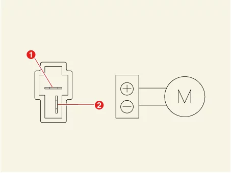
1. Power ( + )
|
2. Ground (-)
|
|
| 3.
|
If the blower motor does not work, replace it with a new blower motor.
|
Blower Motor Removal and Installation
|
The indication below represents the location of a clip or fastener.

|
| 1.
|
Disconnect the battery negative (-) terminal.
|
| 2.
|
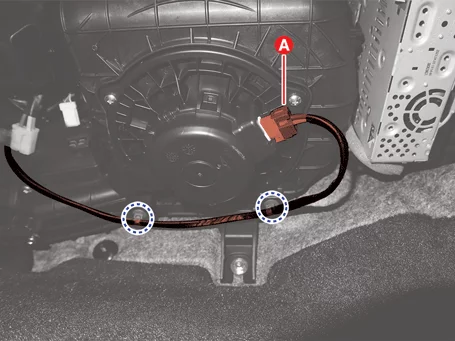
Disconnect the blower motor connector (A).
|
| 3.
|
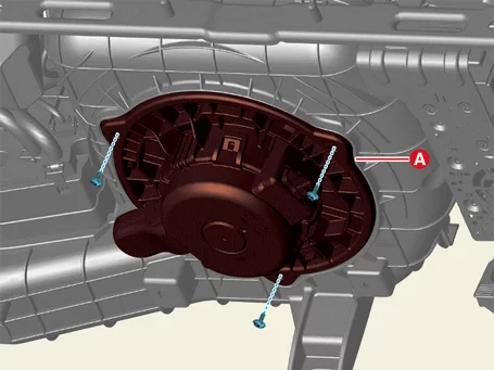
Remove the blower motor (A) after removing the screws.
|
| 1.
|
Install in the reverse order of removal.
|
Blower Unit Removal and Installation
|
•
|
This video was created using 3D graphics to help understand the vehicle
maintenance manual.
|
|
•
|
There may be some differences from actual vehicles.
|
|
•
|
The location and repair procedures of the parts may vary depending on vehicle
model, model year,
region, and specifications.
|
|
•
|
Check the KDS Guide for detailed information on how to use the KDS.
|
|
•
|
Check the manual for detailed maintenance procedures.
|
|
•
|
Unauthorized reproduction, distribution, or sharing of this video is
prohibited.
|
|
Heater Unit Removal
(Click to play)

Video: Heater Unit Removal
|
The indication below represents the location of a clip or fastener.
|
| 1.
|
Recover the refrigerant by using recovery/recycling/charging equipment.
(Refer to Air Conditioning System - "Refrigerant
Recovery/Recycling/Charging/Vacuum/Leak Test")
|
| 2.
|
Drain the coolant.
(Refer to Engine Mechanical System - "Coolant")
|
| 3.
|
Remove the front wiper motor.
(Body - "Wiper Motor")
|
| 4.
|
Remove the front pillar trim.
(Refer to Body - "Front Pillar Trim")
|
| 5.
|
Remove the crash pad center panel.
(Refer to Body - "Crash Pad Panel")
|
| 6.
|
Remove the powernet domain controller.
(Refer to Body - "Junction Block")
|
| 7.
|
Lower the steering column after removing the nuts and through-bolt.
(Refer to Steering System - "Steering Column Assembly")
|
| 8.
|
Remove the rear heating duct assembly.
(Refer to Heater - "Duct")
|
| 9.
|
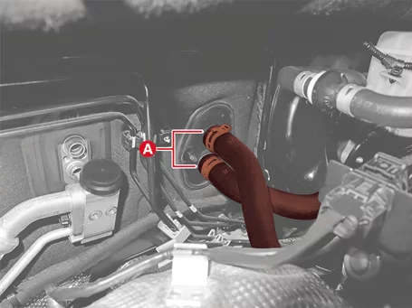
Disconnect the heater hoses (A) after releasing the clamps.
|
| 10.
|
Disconnect the main wiring harness connectors.
| (1)
|
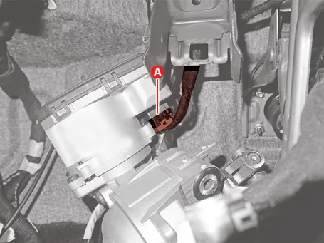
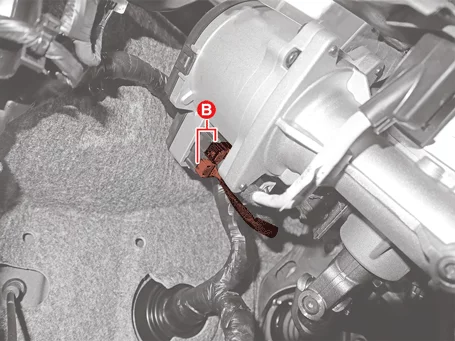
Disconnect the MDPS connectors (A, B).
A : MDPS power connector
B : MDPS signal connector
|
| (2)
|
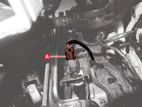
Disconnect the brake switch connector (A).
|
|
| 11.
|
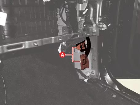
Disconnect the multi-box connectors (A).
Driver's Side
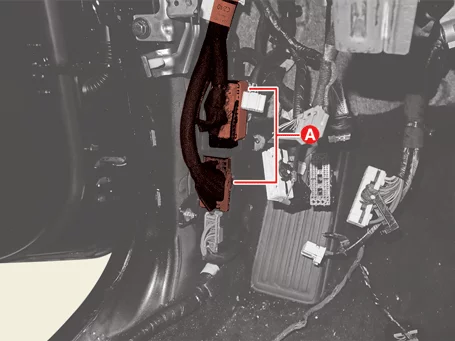
Passenger's Side
|
| 12.
|
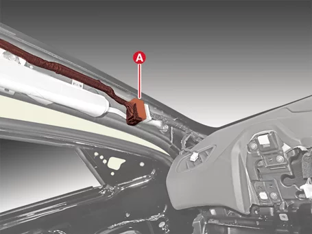
Disconnect the roof trim connector (A).
|
| 13.
|
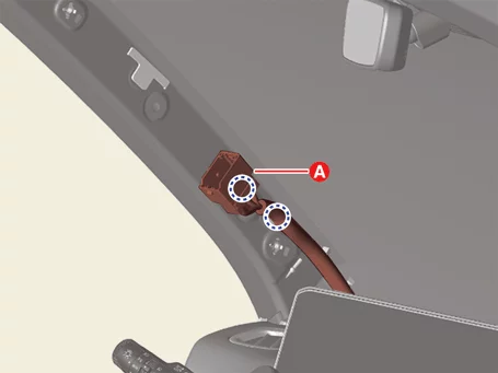
Separate the roof trim wiring (A).
|
| 14.
|
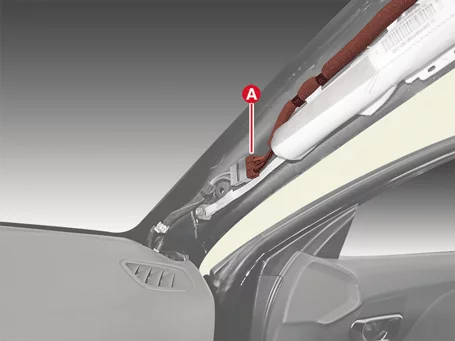
Disconnect the roof antenna connector (A).
|
| 15.
|
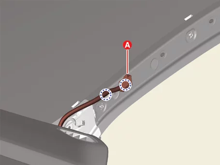
Separate the roof antenna wiring (A).
|
| 16.
|
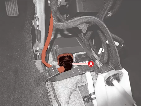
Disconnect the Airbag Control Unit (ACU) connector (A).
|
| 17.
|
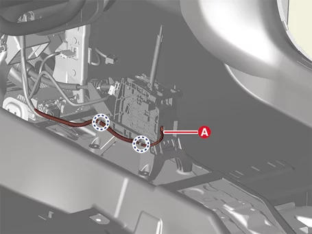
Disconnect the shift lever connector (A).
|
| 18.
|
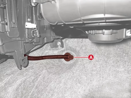
Separate the drain hose (A).
|
| 19.
|
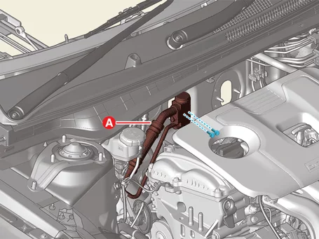
Separate the expansion valve (A) after removing the bolts.
|
Tightening torque:
8.8 - 13.7 N·m (0.9 - 1.4 kgf·m, 6.5 - 10.1 lb·ft)
|
|
| 20.
|
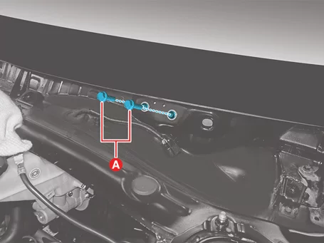
Remove the dash panel cowl cross bar through-bolts (A).
|
Tightening torque:
16.7 - 25.5 N·m (1.7 - 2.6 kgf·m, 12.3 - 18.8 lb·ft)
|
|
| 21.
|
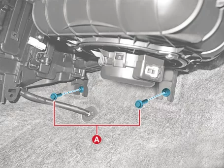
Remove the heater and blower unit lower bolt (A).
|
Tightening torque:
3.9 - 5.9 N·m (0.4 - 0.6 kgf·m, 2.9 - 4.3 lb·ft, 34.7 - 52.1 lb·in)
|
|
| 22.
|
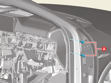
Remove the side panel cowl cross bar through-bolts (A).
|
Tightening torque:
16.7 - 25.5 N·m (1.7 - 2.6 kgf·m, 12.3 - 18.8 lb·ft)
|
Driver's Side
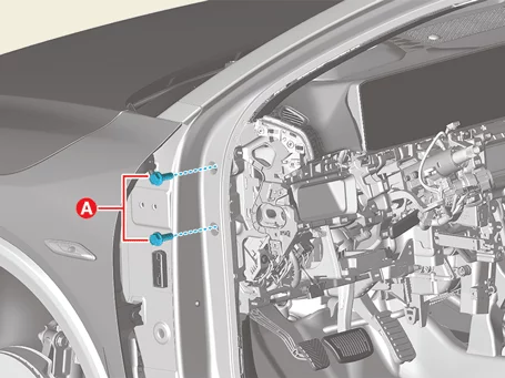
Passenger's Side
|
| 23.
|
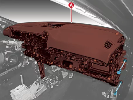
Remove the crash pad, heater and blower unit (A) after removing the bolts.
|
Tightening torque:
16.7 - 25.5 N·m (1.7 - 2.6 kgf·m, 12.3 - 18.8 lb·ft)
|
Driver's Side
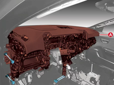
Passenger's Side
|
| 24.
|
Disconnect the main wiring harness connectors. [Driver's
side]
A : Temperature control actuator connector
B : Mode control actuator connector
C : PTC heater connector
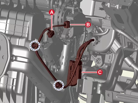
|
| 25.
|
Disconnect the main wiring harness connectors. [Passenger's
side]
| (1)
|
Disconnect the connectors (A, B, C).
A : Evaporator temperature sensor
connector
B : PWM-FET connector
C : Blower motor connector
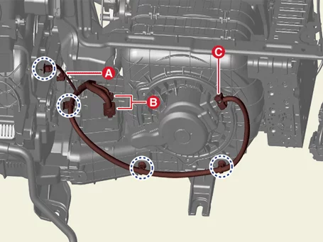
|
| (2)
|
Disconnect the connectors (A, B).
A : Temperature control actuator
connector
B : Intake actuator connector
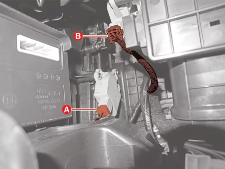
|
| (3)
|
Disconnect the auto defogging actuator connector (A).
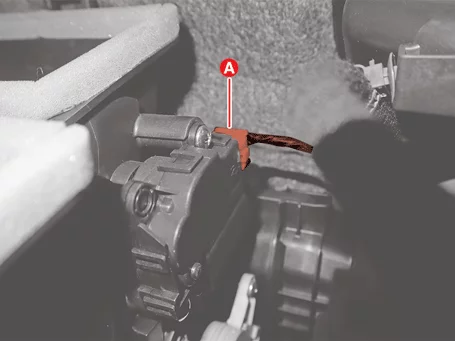
|
|
| 26.
|
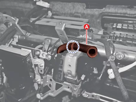
Separate the in-car sensor hose (A).
|
| 27.
|
Remove the heater and blower unit.
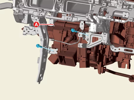
| (1)
|
Separate the heater and blower unit (A) after removing the bolts.
|
Tightening torque:
3.9 - 5.9 N·m (0.4 - 0.6 kgf·m, 2.9 - 4.3 lb·ft, 34.7 - 52.1
lb·in)
|
|
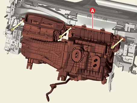
| (2)
|
Remove the heater and blower unit (A) after removing the nuts.
|
Tightening torque:
3.9 - 5.9 N·m (0.4 - 0.6 kgf·m, 2.9 - 4.3 lb·ft, 34.7 - 52.1
lb·in)
|
|
|
| 28.
|
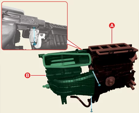
Separate the heater unit (A) and the blower unit (B) after removing the screws.
|
| 29.
|
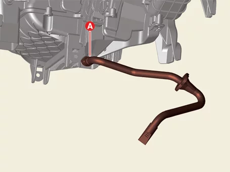
Remove the heater drain hose (A).
|
| 1.
|
Install in the reverse order of removal.
|
•
|
Perform the refrigerant leak test/vacuum/charging by using the
refrigerant
recovery/recycling/charging machine.
(Refer to Air Conditioning
System - "Refrigerant
Recovery/Recycling/Charging/Vacuum/Leak Test")
|
|
•
|
Perform the compressor oil inspection.
(Refer to Air Conditioning
System - "Compressor
Oil")
|
|
|
Climate Control Air Filter Description and Operation
The air filter for the air conditioner installed on the blower unit removes foreign substances or odors. The
particle filter not only removes general dust but also serves as a odor-removing filter to maintain a
comfortable
indoor environment.
Climate Control Air Filter Replacement
|
The indication below represents the location of a clip or fastener.
|
| 1.
|
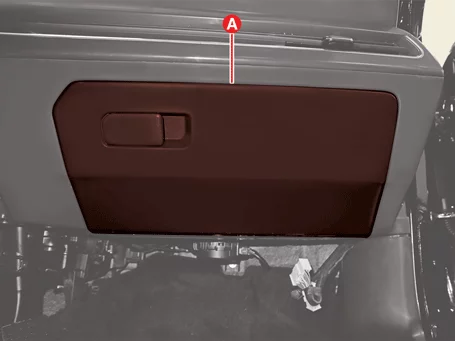
Open the glove box (A).
|
| 2.
|
Remove the stoppers (A).
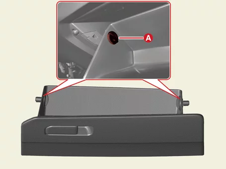
|
| 3.
|
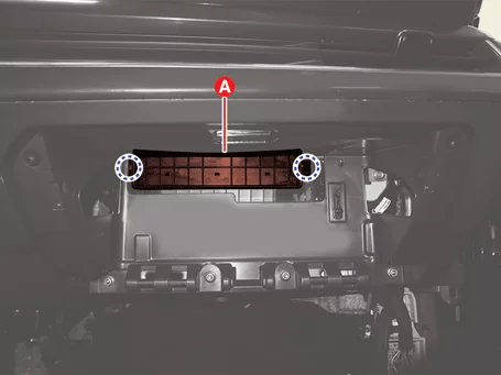
Remove the air filter cover (A).
|
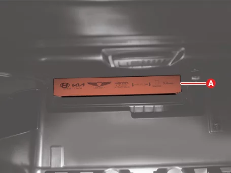
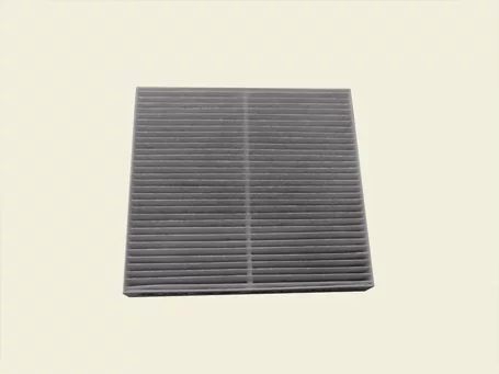
| 4.
|
Replace the air filter (A).
|
•
|
Replace the air filter for air conditioning according to the
replacement interval of the
instruction manual.
|
|
•
|
When driving in an area with severe air pollution or an area
where a lot of fumes are
generated due to poor road conditions, frequent inspections and
replacements are required.
|
|
|
Intake Actuator Description and Operation
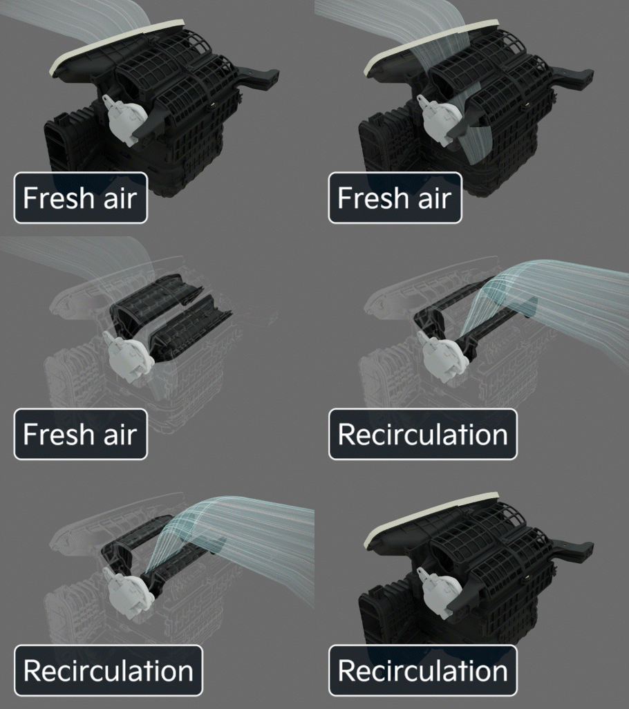
It is operated by a heater and A/C controller and controls the position of the intake door to adjust the fresh
air mode / recirculation mode.
Intake Actuator Removal and Installation
| 1.
|
Remove the crash pad assembly.
(Refer to Body - "Crash Pad Assembly")
|
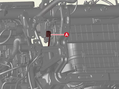
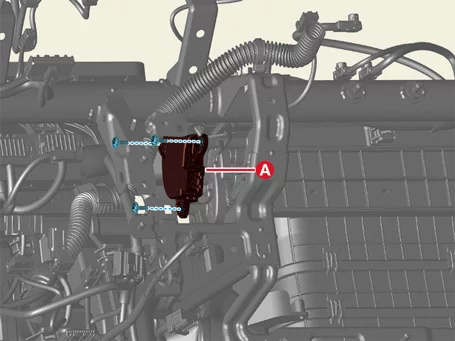
| 2.
|
Disconnect the intake actuator connector (A).
|
| 3.
|
Remove the actuator after removing the screws.
|
| 1.
|
Install in the reverse order of removal.
|
Intake Actuator Inspection
| 1.
|
Disconnect the intake actuator connector.
(Refer to Blower - "Intake Actuator")
|
| 2.
|
Apply voltage to the intake actuator 3 terminal and ground the 7 terminal to check whether the
actuator
operates.
|
| 3.
|
When connecting in the opposite, check if it operates in reverse.
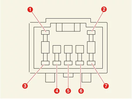
1. -
2. -
3.
Recirculated Air
4.
Sensor Ground
|
5. Feedback Signal
6.
Sensor Power (5
V)
7. Fresh Air
|
|
| 4.
|
Connect the intake actuator connector.
|
| 6.
|
Measure the voltage of the 4 - 5 terminal.
Door Position
|
Voltage (V)
|
Error Detection
|
Fresh Air
|
0.15 - 0.45
|
Low voltage : below 0.1 V
High voltage : above 4.9 V
|
Recirculation
|
4.55 - 4.85
|
|
| 7.
|
If the measured voltage does not match with the specification, replace it with a new intake
actuator.
|
PWM-FET Description and Operation
The fan speed is adjusted by precisely controlling the voltage applied to the blower motor.
PWM-FET Removal and Installation
| 1.
|
Disconnect the battery negative (-) terminal.
|
| 2.
|
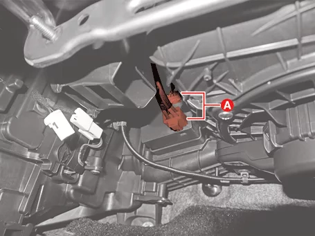
Disconnect the PWM-FET connectors (A).
|
| 3.
|
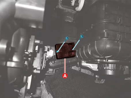
Remove the PWM-FET (A) after removing the screws.
|
| 1.
|
Install in the reverse order of removal.
|
PWM-FET Inspection
| 1.
|
Disconnect the PWM-FET connector.
(Refer to Blower - "PWM-FET")
|
| 2.
|
Measure the voltage between the terminals of the blower motor by manually operating the control
switch.
| (1)
|
Terminal
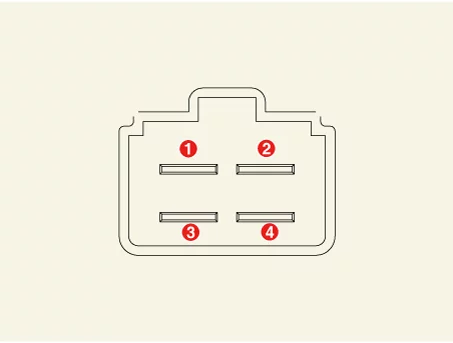
1. Drain
3.
Source
|
2. Drain
Feedback
4. Gate
|
|
| (2)
|
Circuit Diagram
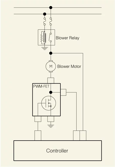
|
|
Other information:
Kia K4 (CL4) 2025-2026 Service Manual: Intelligent Speed Limit Assist (ISLA):
The Intelligent Speed Limit Assist (ISLA) system in the Kia K4 enhances your driving awareness by integrating data from detected traffic signs and the onboard navigation system. It proactively informs you of current speed restrictions to help you maintain compliance with local traffic laws.
TIP
The Intelligent Speed Limit Assist may have limited operational capacity or accuracy if utilized in regions outside of the original market for which the Kia K4 was designed.
Kia K4 (CL4) 2025-2026 Service Manual: Special driving conditions
Navigating through adverse weather or challenging road surfaces requires a heightened level of driver awareness and caution. When road conditions deteriorate, you must adjust your driving habits to ensure the continued safety and stability of your Kia K4.
Hazardous driving conditions
Whenever you encounter treacherous elements such as standing water, deep snow, ice, thick mud, or loose sand, please adhere to these professional driving suggestions to maintain better control of your Kia K4:
Drive with extreme caution and increase your following distance.