Contents:
Components and Components Location
Body Side Molding [4DR]
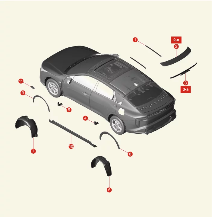
1. Roof Side Molding
2. Deck
Garnish
2-a. 4.0 -
6.0 N·m (0.41 - 0.61 kgf·m, 3.0 - 4.4 lb·ft, 35.6 - 52.9 lb·in)
3. Trunk Lid Garnish
3-a. 4.0
- 6.0 N·m
(0.41 - 0.61 kgf·m, 3.0 - 4.4 lb·ft, 35.6 - 52.9 lb·in)
4. Rear Mud Guard
5. Front Mud
Guard
|
6. Rear Wheel Guard
7. Front Wheel
Guard
8.
Quarter Garnish
9. Fender Garnish
10. Side Sill Molding
11. A Pillar Garnish
|
Body Side Molding [5DR]
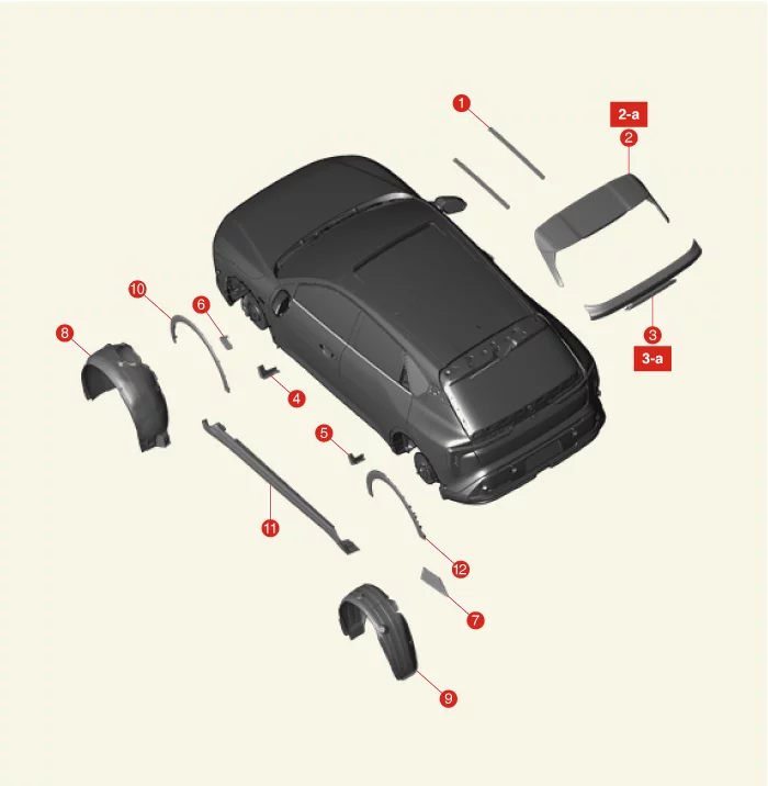
1. Roof Side Molding
2. Rear
Spoiler
2-a. 6.0 -
9.0 N·m (0.61 - 0.92 kgf·m, 4.4 - 6.7 lb·ft, 52.9 - 79.9 lb·in)
3. Tailgate Garnish
3-a. 4.0
- 6.0 N·m
(0.41 - 0.61 kgf·m, 3.0 - 4.4 lb·ft, 35.6 - 52.9 lb·in)
4. Front Mud Guard
5. Rear Mud
Guard
|
6. A Pillar Garnish
7. C Pillar
Garnish
8. Front
Wheel Guard
9. Rear Wheel Guard
10. Fender Garnish
11. Side Sill Molding
12. Quarter
Garnish
|
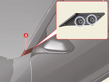
A Pillar Garnish Removal and Installation
|
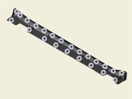
The indication below represents the location of a clip or fastener.

|
| 1.
|
Remove the A pillar garnish (A).
|
| 1.
|
Install in the reverse order of removal.
|
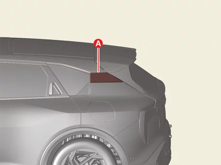
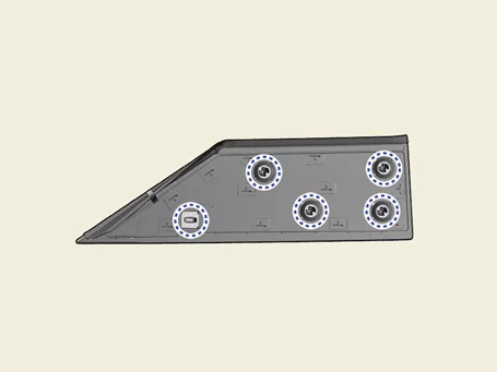
C Pillar Garnish Removal and Installation
|
The indication below represents the location of a clip or fastener.
|
| 1.
|
Remove the C pillar garnish (A).
|
| 1.
|
Install in the reverse order of removal.
|
Deck Garnish Removal and Installation
|
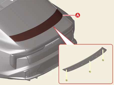
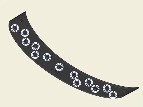
The indication below represents the location of a clip or fastener.
|
| 1.
|
Remove the trunk lid trim.
(Refer to Trunk Lid - "Trunk Lid Trim")
|
| 2.
|
Remove the deck garnish (A) after removing the nuts.
|
Tightening torque :
4.0 - 6.0 N·m (0.41 - 0.61 kgf·m, 3.0 - 4.4 lb·ft, 35.6 - 52.9 lb·in)
|
|
| 1.
|
Install in the reverse order of removal.
|
Emblem Removal and Installation (Front)
|
•
|
This video was created using 3D graphics to help understand the vehicle
maintenance manual.
|
|
•
|
There may be some differences from actual vehicles.
|
|
•
|
The location and repair procedures of the parts may vary depending on vehicle
model, model year,
region, and specifications.
|
|
•
|
Check the KDS Guide for detailed information on how to use the KDS.
|
|
•
|
Check the manual for detailed maintenance procedures.
|
|
•
|
Unauthorized reproduction, distribution, or sharing of this video is
prohibited.
|
|
Front Emblem Installation (New Part)
(Click to play)

Video: Front Emblem Installation (New Part)
Front Emblem Replacement
(Click to play)
Video: Front Emblem Replacement
|
•
|
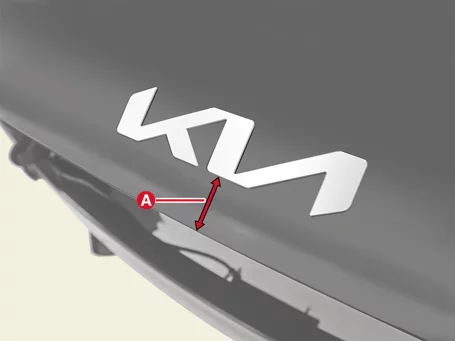
Standard of measurement : From the end of the hood to the bottom of the emblem (center of the
vehicle).
|
|
•
|
Length (A) considering curved surface : 20 mm (0.79 in.)
|
|
•
|
When removing the emblem, be careful not to damage the body or painted surface.
|
|
•
|
When using a heating gun, be careful not to damage the painted surface.
|
|
| 1.
|
Mark the center of the emblem.
|
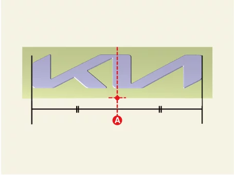
Since the center of the emblem "I" is not located at the center of the vehicle,
refer to the
procedure below to mark the center.
|
| (1)
|
Mark the center (A) after measuring the horizontal length of the emblem.
|
The shape of the emblem foam pad may be different for vehicles.
|
|
If the width is 21 cm (8.27 in.), the 10.5 cm (4.13 in.) part
coincides with the center
of the vehicle. As shown in the image below, the part that is
skewed to the left of "I" is
the center.
|
|
| (2)
|
Mark the center of the emblem on the foam pad.
|
|
| 2.
|
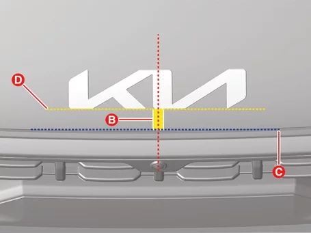
Measure the distance of the curved surface from the reference point and attach the emblem to
the vehicle
center.
B : Length of curved surface (C - D) 20 mm (0.79 in.)
C : Bottom end of the hood
D : Middle end of the emblem
|
The attachment location is a value set based on the end of the emblem, not the
end of the foam
pad.
|
|
| 3.
|
Use a tool such as a roller to attach it closely to the vehicle body after attaching the
emblem.
|
| 1.
|
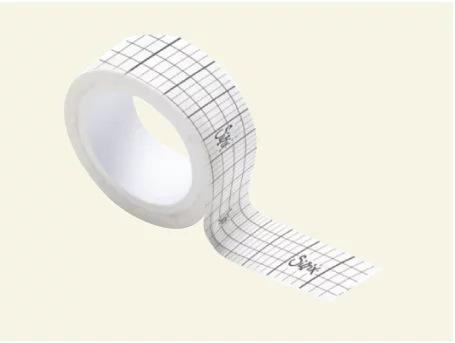
The following products can be utilized to accurately determine the location of the emblem
attachment.
| A. |
Self-adhesive measuring tape
|
| B. |
Attachable tape measure (Steel products may damage the vehicle)
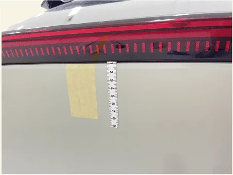
|
| C. |
General masking tape
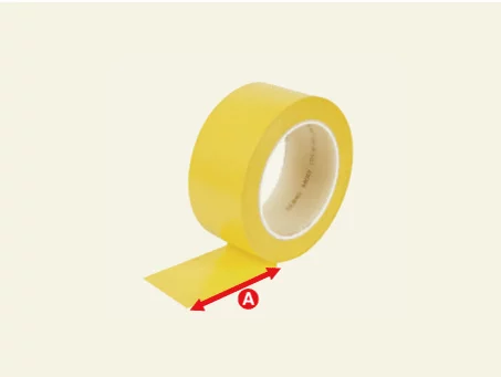
|
|
| 2.
|
The center of the vehicle is based on the end of hood.
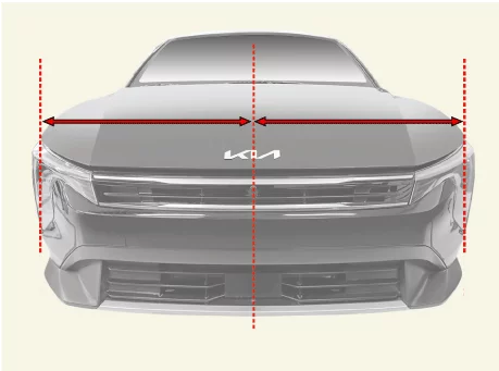
|
Emblem Removal and Installation (Rear)
|
•
|
This video was created using 3D graphics to help understand the vehicle
maintenance manual.
|
|
•
|
There may be some differences from actual vehicles.
|
|
•
|
The location and repair procedures of the parts may vary depending on vehicle
model, model year,
region, and specifications.
|
|
•
|
Check the KDS Guide for detailed information on how to use the KDS.
|
|
•
|
Check the manual for detailed maintenance procedures.
|
|
•
|
Unauthorized reproduction, distribution, or sharing of this video is
prohibited.
|
|
Rear Emblem Installation (New part)
(Click to play)
Video: Rear Emblem Installation_New Part
Installation
Rear Emblem Replacement
(Click to play)
Video: Rear Emblem Replacement
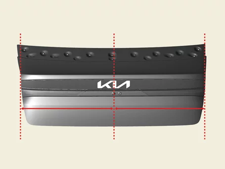
|
•
|
Standard of measurement : from the top end of the trunk lid garnish to the top of the emblem
(vehicle
center).
|
|
•
|
Length (A) considering curved surface : 16 mm (0.64 in.)
|
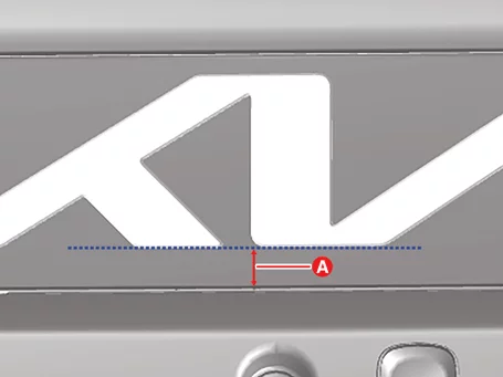
|
•
|
When removing the emblem, be careful not to damage the body or painted surface.
|
|
•
|
When using a heating gun, be careful not to damage the painted surface.
|
|
| 1.
|
Mark the center of the emblem.
|
Since the center of the emblem "I" is not located at the center of the vehicle,
refer to the
procedure below to mark the center.
|
| (1)
|
Mark the center (A) after measuring the horizontal length of the emblem
|
The shape of the emblem foam pad may be different for vehicles.
|
|
If the width is 21 cm (8.27 in.), the 10.5 cm (4.13 in.) part
coincides with the center
of the vehicle. As shown in the image below, the part that is
skewed to the left of "I" is
the center.
|
|
| (2)
|
Mark the center of the emblem on the foam pad.
|
|
| 2.
|
Measure the distance of the curved surface from the reference point and attach the emblem to
the vehicle
center.
B : Length of curved surface (C - D) 16 mm (0.64 in.)
C : Bottom end of the trunk lid garnish.
D : Middle end of the emblem
|
The attachment location is a value set based on the end of the emblem, not the
end of the foam
pad.
|
|
| 3.
|
Use a tool such as a roller to attach it closely to the vehicle body after attaching the
emblem.
|
| 1.
|
The following products can be utilized to accurately determine the location of the emblem
attachment.
| A. |
Self-adhesive measuring tape
|
| B. |
Attachable tape measure (Steel products may damage the vehicle)
|
| C. |
General masking tape
|
|
| 2.
|
The center of the vehicle is based on the rear combination lamp end.
|
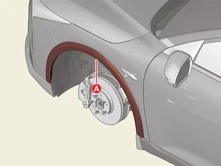
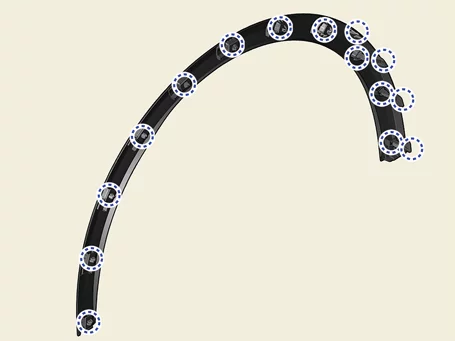
Fender Garnish Removal and Installation
|
The indication below represents the location of a clip or fastener.
|
| 1.
|
Remove the fender garnish (A).
|
| 1.
|
Install in the reverse order of removal.
|
Mud Guard Removal and Installation
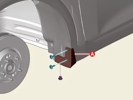
Front Mud Guard
| 1.
|
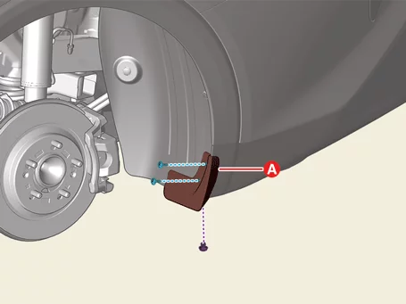
Remove the mud guard (A) after removing the screws and fastener.
|
Rear Mud Guard
| 1.
|
Remove the mud guard (A) after removing the screws and fastener.
|
| 1.
|
Install in the reverse order of removal.
|
Quarter Garnish Removal and Installation
|
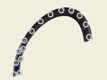
The indication below represents the location of a clip or fastener.
|
| 1.
|
Remove the side sill molding.
(Refer to Body Side Molding - "Side Sill Molding")
|
| 2.
|
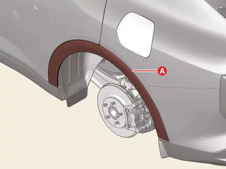
Remove the quarter garnish (A).
|
| 1.
|
Install in the reverse order of removal.
|
Rear Spoiler Removal and Installation
|
The indication below represents the location of a clip or fastener.
|
Rear Spoiler
| 1.
|
Disconnect the battery negative (-) terminal.
|
| 2.
|
Remove the tailgate upper trim.
(Refer to Tailgate - "Tailgate Trim")
|
| 3.
|
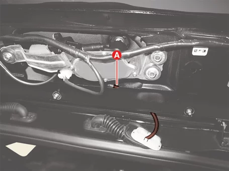
Disconnect the washer nozzle (A).
|
| 4.
|
Disconnect the high mounted stop lamp connector (A).
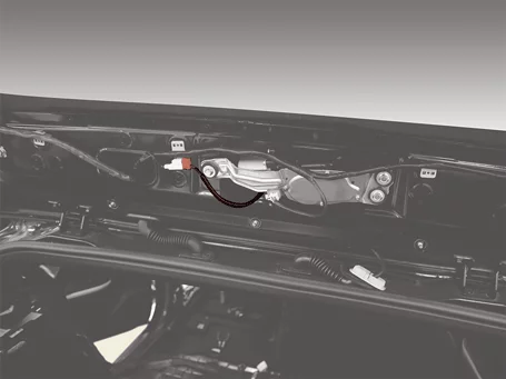
|
| 5.
|
Remove the hole plugs (A).
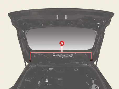
|
| 6.
|
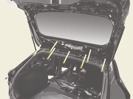
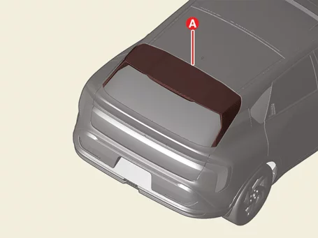
Remove the rear spoiler (A) after removing the nuts.
|
Tightening torque:
6.0 - 9.0 N·m (0.61 - 0.92 kgf·m, 4.4 - 6.7 lb·ft, 52.9 - 79.9 lb·in)
|
|
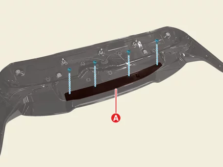
High Mounted Stop Lamp Cover
| 1.
|
Remove the rear spoiler.
|
| 2.
|
Remove the cover (A) after removing the screws.
|
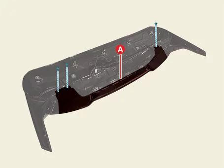
Rear Spoiler Under Cover
| 1.
|
Remove the high mounted stop lamp cover.
|
| 2.
|
Remove the cover (A) after removing the screws.
|
| 1.
|
Install in the reverse order of removal.
|
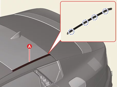
Roof Side Molding Removal and Installation
|
The indication below represents the location of a clip or fastener.
|
| 1.
|
Remove the roof side molding (A).
|
| 1.
|
Install in the reverse order of removal.
|
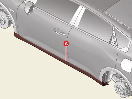
Side Sill Molding Removal and Installation
|
The indication below represents the location of a clip or fastener.
|
| 1.
|
Remove the front and rear wheel guard.
(Refer to Body Side Molding - "Wheel Guard")
|
| 2.
|
Remove the fender garnish.
(Refer to Body Side Molding - "Fender Garnish")
|
| 3.
|
Remove the side sill molding (A).
|
| 1.
|
Install in the reverse order of removal.
|
Tailgate Garnish Removal and Installation
|
The indication below represents the location of a clip or fastener.
|
| 1.
|
Disconnect the battery negative (-) terminal.
|
| 2.
|
Remove the tailgate lower trim.
(Refer to Tailgate - "Tailgate Trim")
|
| 3.
|
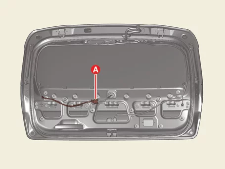
Disconnect the tailgate garnish connector (A).
|
| 4.
|
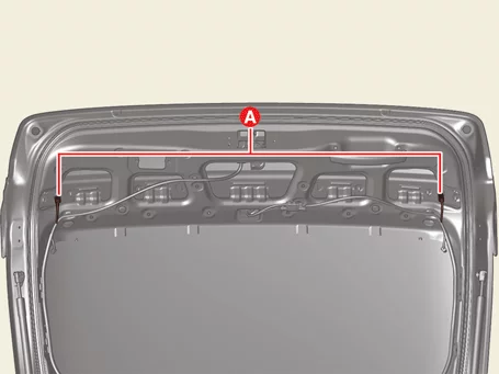
Disconnect the rear combination lamp connectors (A).
|
| 5.
|
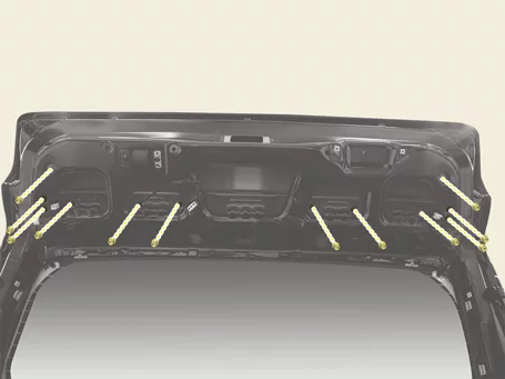
Remove the tailgate garnish (A) after removing the nuts.
|
Tightening torque:
4.0 - 6.0 N·m (0.41 - 0.61 kgf·m, 3.0 - 4.4 lb·ft, 35.6 - 52.9 lb·in)
|
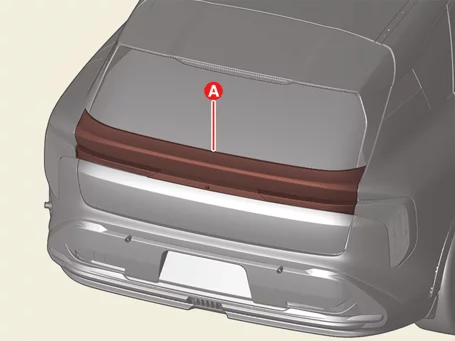
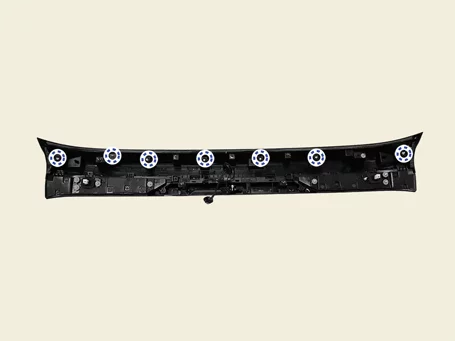
|
| 1.
|
Install in the reverse order of removal.
|
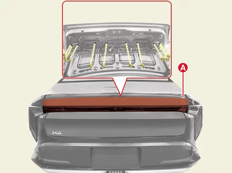
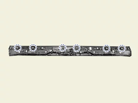
Trunk Lid Garnish Removal and Installation
|
The indication below represents the location of a clip or fastener.
|
| 1.
|
Disconnect the battery negative (-) terminal.
|
| 2.
|
Remove the trunk lid trim.
(Refer to Trunk Lid - "Trunk Lid Trim")
|
| 3.
|
Disconnect the connectors (A, B, C).
A : Wide angle camera connector
B : Inside rear combination lamp connector [Driver's side]
C : Inside rear combination lamp connector [Passenger's side]
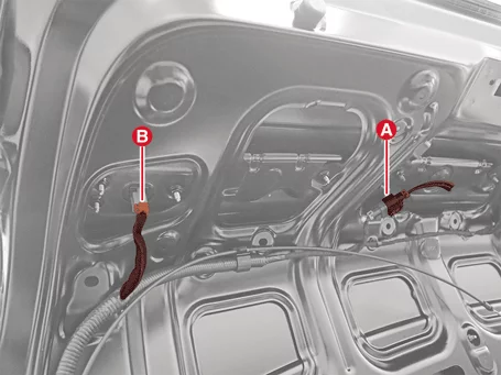
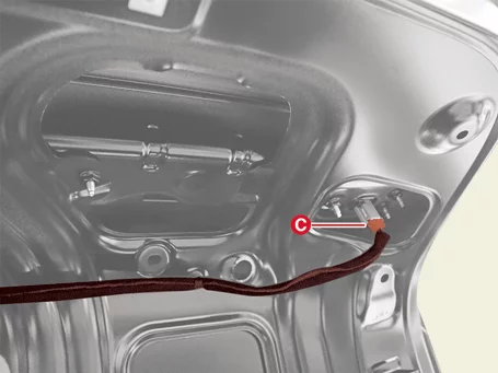
|
| 4.
|
Remove the trunk lid garnish (A) after removing the nuts.
|
Tightening torque
4.0 - 6.0 N·m (0.41 - 0.61 kgf·m, 3.0 - 4.4 lb·ft, 35.6 - 52.9 lb·in)
|
|
| 1.
|
Install in the reverse order of removal.
|
Wheel Guard Removal and Installation
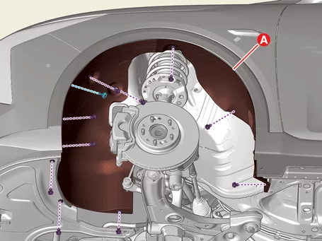
Front Wheel Guard
| 1.
|
Remove the front wheel and tire.
(Refer to Suspension System - "Wheel")
|
| 2.
|
Remove the front mud guard.
(Refer to Body Side Molding - "Mud Guard")
|
| 3.
|
Remove the wheel guard (A) after removing the screw and fasteners.
|
Clip position :
|
|
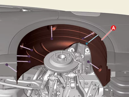
Rear Wheel Guard
| 1.
|
Remove the rear wheel and tire.
(Refer to Suspension System - "Wheel")
|
| 2.
|
Remove the rear mud guard.
(Refer to Body Side Molding - "Mud Guard")
|
| 3.
|
Remove the wheel guard (A) after removing the screw and fasteners.
|
Clip position :
|
|
| 1.
|
Install in the reverse order of removal.
|
Other information:
Kia K4 (CL4) 2025-2026 Service Manual: Personalized profile and vehicle settings
Integrating your virtual wallet credentials with the vehicle's memory framework unlocks advanced customization capabilities. When you link a registered smartphone containing an active Digital Key 2 profile with an individualized user profile, the vehicle automatically adjusts its physical and software environments to your preferences the moment you unlock the door or approach the perimeter.
Kia K4 (CL4) 2025-2026 Service Manual: Highway Driving Assist settings
Driver Assistance
Driving Convenience
Highway Driving Assist
While the vehicle is powered ON, access your Kia K4 infotainment system and tap Setup > Vehicle > Driver Assistance > Driving Convenience to configure the customized options for each driver-assist function.