Contents:
Components and Components Location
| Component and Component Location |
Crash Pad [Top]
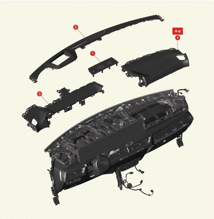
1. Center Speaker Grille
2. Crash Pad Top
Cover
3. Crash Pad Upper Panel [Driver's side]
|
4. Crash Pad Upper Panel [Passenger's
side]
4-a.
6.9 - 10.8 N·m (0.7 - 1.1 kgf·m, 5.1 - 8.0 lb·ft)
|
Crash Pad [Driver's Side]
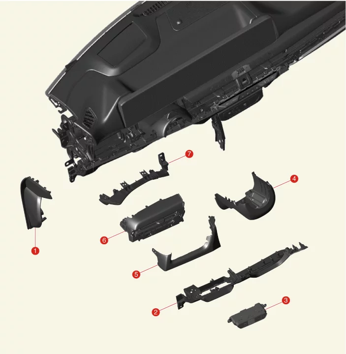
1. Crash Pad Side Cover [Driver's side]
2.
Crash
Pad Lower Panel
3. Crash Pad Switch
4. Lower Steering Column Shroud Panel
|
5. Crash Pad Lower Garnish [Driver's
side]
6. Crash
Pad Air Vent [Driver's side]
7. Crash Pad Mood Lamp [Driver's side]
|
Crash Pad [Passenger's Side]
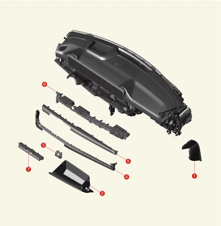
1. Crash Pad Side Cover [Passenger's
side]
2. Glove
Box
3. Hazard Switch Cover
4. Crash Pad Lower Garnish [Passenger's side]
|
5. Crash Pad Upper Garnish [Passenger's
side]
6.
Crash Pad Air Vent [Passenger's side]
7. Infotainment Keyboard
|
Crash Pad [Center]
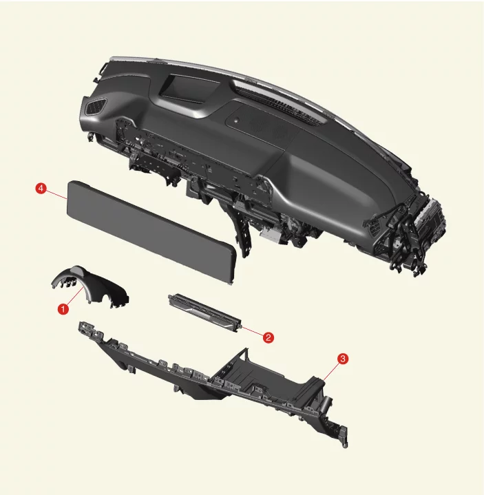
1. Upper Steering Column Shroud Panel
2.
Heater and
Air Conditioning Controller
|
3. Crash Pad Center Panel
4. Integrated
Monitor
|
Crash Pad Assembly
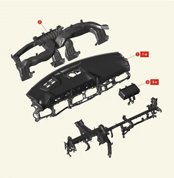
1. Crash Pad Assembly
1-a. 6.9 - 10.8 N·m
(0.7 -
1.1 kgf·m, 5.1 - 8.0 lb·ft)
2. Crash Pad Air Vent Duct Assembly
|
3. Passenger Airbag (PAB) Module
3-a. 3.9 -
5.9 N·m
(0.4 - 0.6 kgf·m, 2.9 - 4.3 lb·ft, 34.7 - 52.1 lb·in)
|
Cowl Cross Bar
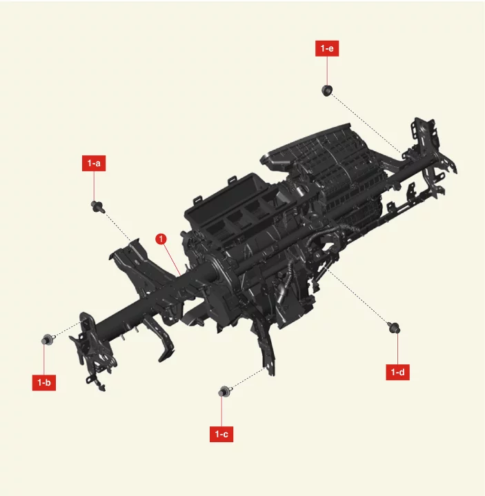
1. Cowl Cross Bar
1-a. 16.7 - 25.5 N·m (1.7
- 2.6
kgf·m, 12.3 - 18.8 lb·ft)
1-b. 16.7 - 25.5 N·m (1.7 - 2.6 kgf·m, 12.3 - 18.8 lb·ft))
|
1-c. 16.7 - 25.5 N·m (1.7 - 2.6 kgf·m, 12.3 -
18.8
lb·ft)
1-d. 3.9 - 5.9 N·m (0.4 - 0.6 kgf·m, 2.9 - 4.3 lb·ft, 34.7 - 52.1 lb·in)
1-e. 3.9 -
5.9 N·m (0.4
- 0.6 kgf·m, 2.9 - 4.3 lb·ft, 34.7 - 52.1 lb·in)
|
Cowl Cross Bar Assembly Removal and Installation
|
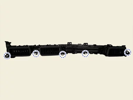
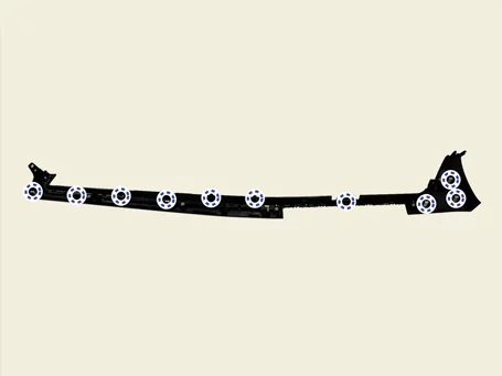
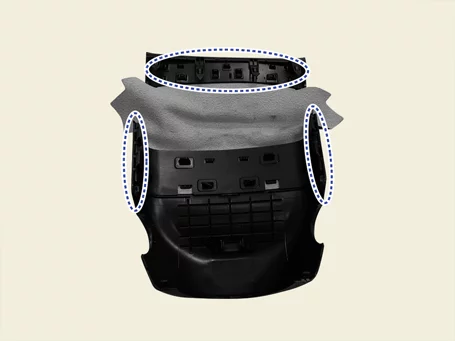
The indication below represents the location of a clip or fastener.

|
| 1.
|
Remove the crash pad assembly.
(Refer to Crash Pad - "Crash Pad Assembly")
|
| 2.
|
Remove the powernet domain controller.
(Refer to Security & Vehicle Ignition System - "Junction
Block")
|
| 3.
|
Remove the Central Communication Unit (CCU).
(Refer to Security & Vehicle Ignition System - "Central
Communication
Unit (CCU)")
|
| 4.
|
Lower the steering column after removing the nuts and through-bolt.
(Refer to Steering System - "Steering Column Assembly")
|
| 5.
|
Remove the front wiper motor.
(Refer to Exterior Green House - "Wiper Motor")
|
| 6.
|
Remove the duct. [Both side]
(Refer to Heating, Ventilation and Air Conditioning -
"Duct")
|
| 7.
|
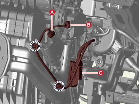
Disconnect the main wiring harness connectors. [Driver's
side]
| (1)
|
Disconnect the connectors (A, B, C).
A : Temperature control actuator
connector
B : Mode control actuator connector
C : PTC heater connector
|
| (2)
|
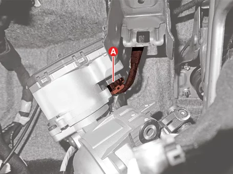
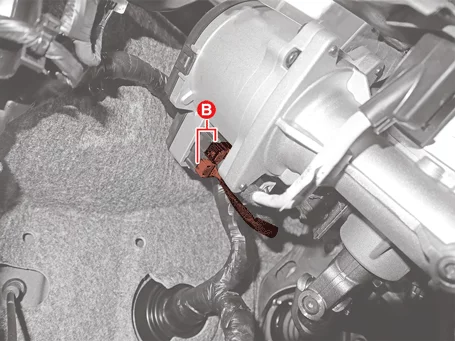
Disconnect the Motor Driven Power Steering (MDPS) connectors (A, B).
A : MDPS power connector
B : MDPS signal connector
|
| (3)
|
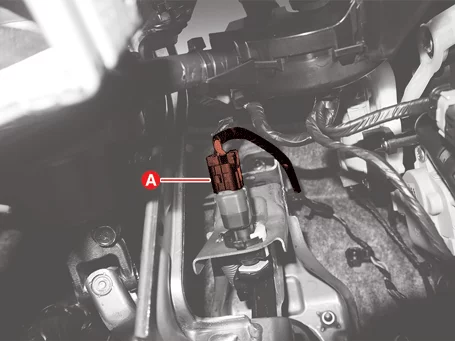
Disconnect the brake switch connector (A).
|
|
| 8.
|
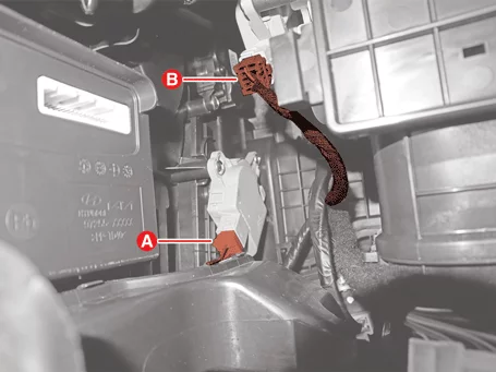
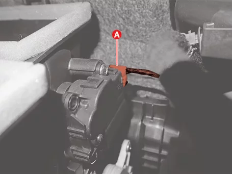
Disconnect the main wiring harness connectors. [Passenger's
side]
| (1)
|
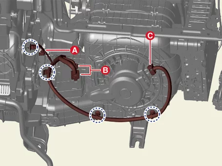
Disconnect the connectors (A, B, C).
A : Evaporator temperature sensor
connector
B : PWM-FET connector
C : Blower motor connector
|
| (2)
|
Disconnect the connectors (A, B).
A : Temperature control actuator
connector
B : Intake actuator connector
|
| (3)
|
Disconnect the auto defogging actuator connector (A).
|
|
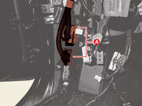
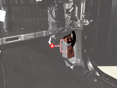
| 9.
|
Disconnect the multi box connectors (A).
Driver's Side
Passenger's Side
|
| 10.
|
Disconnect the roof trim connector (A).
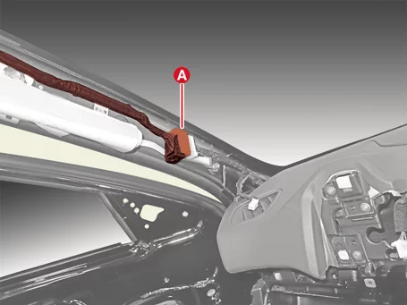
|
| 11.
|
Separate the roof trim wiring (A).
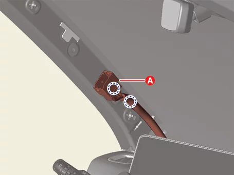
|
| 12.
|
Disconnect the roof shark fin antenna connector (A).
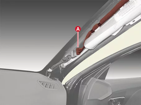
|
| 13.
|
Separate the roof shark fin antenna wiring (A).
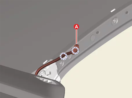
|
| 14.
|
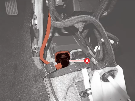
Disconnect the Airbag Control Unit (ACU) connector (A).
|
| 15.
|
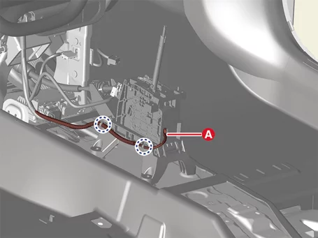
Disconnect the shift lever connector (A).
|
| 16.
|
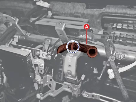
Separate the in-car sensor hose (A) after removing the fastener.
|
| 17.
|
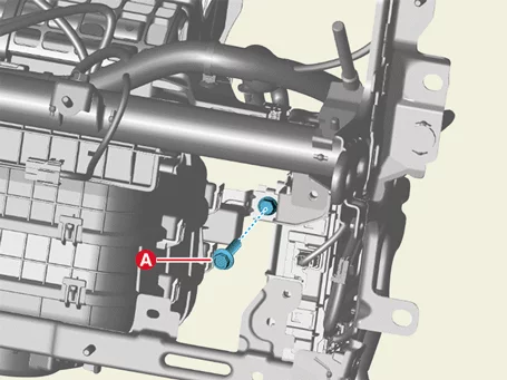
Remove the Body Domain Control Unit (BDC) bolt (A).
|
Tightening torque:
6.6 - 9.9 N·m (0.67 - 1.01 kgf·m, 4.8 - 7.3 lb·ft, 58.2 - 87.7 lb·in)
|
|
| 18.
|
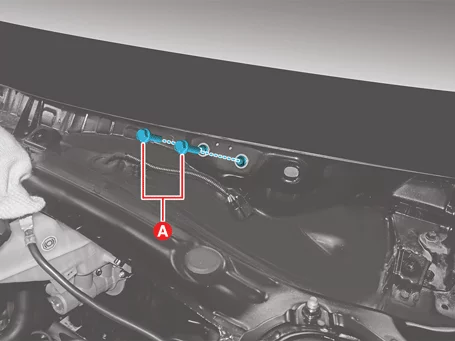
Remove the dash panel cowl cross bar through-bolts.
|
Tightening torque:
16.7 - 25.5 N·m (1.7 - 2.6 kgf·m, 12.3 - 18.8 lb·ft)
|
|
| 19.
|
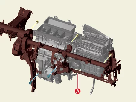
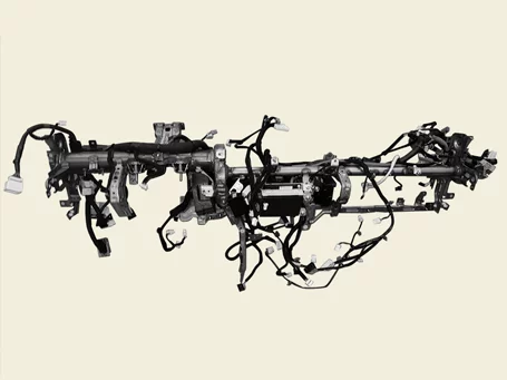
Separate the cowl cross bar assembly (A) after removing the bolts and nuts.
|
Tightening torque :
3.9 - 5.9 N·m (0.4 - 0.6 kgf·m, 2.9 - 4.3 lb·ft, 34.7 - 52.1 lb·in)
|
|
| 20.
|
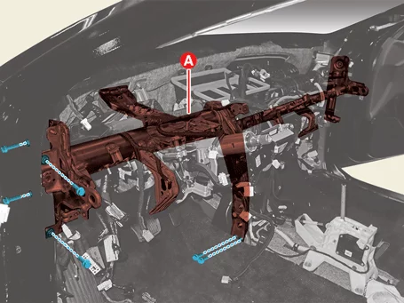
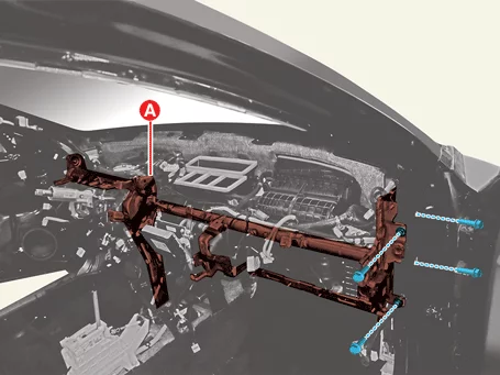
Remove the cowl cross bar assembly (A) after removing the bolts.
|
Tightening torque :
16.7 - 25.5 N·m (1.7 - 2.6 kgf·m, 12.3 - 18.8 lb·ft)
|
|
| 1.
|
Install in the reverse order of removal.
|
Crash Pad Air Vent Removal and Installation
|
The indication below represents the location of a clip or fastener.
|
Crash Pad Air Vent [Driver's Side]
| 1.
|
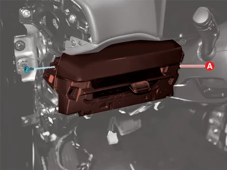
Remove the crash pad lower garnish. [Driver's side]
(Refer to Crash Pad - " Crash Pad Garnish")
|
| 2.
|
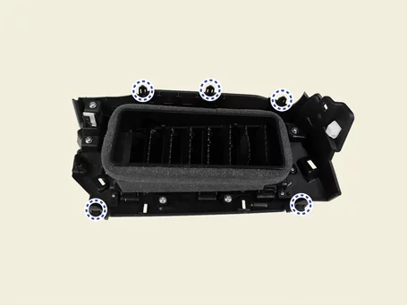
Remove the air vent (A) after removing the screw.
|
Crash Pad Air Vent [Passenger's Side]
| 1.
|
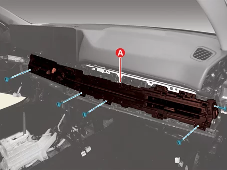
Remove the crash pad upper garnish. [Passenger's side]
(Refer to Crash Pad - " Crash Pad Garnish")
|
| 2.
|
Remove the air vent (A) after removing the screws.
|
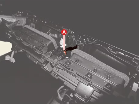
| 3.
|
Disconnect the hazard switch connector (A).
|
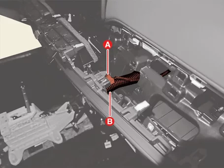
| 4.
|
Disconnect the in-car sensor connector (A) and separate the in-car sensor hose (B).
|
| 1.
|
Install in the reverse order of removal.
|
Crash Pad Assembly Removal and Installation
|
•
|
This video was created using 3D graphics to help understand the vehicle
maintenance manual.
|
|
•
|
There may be some differences from actual vehicles.
|
|
•
|
The location and repair procedures of the parts may vary depending on vehicle
model, model year,
region, and specifications.
|
|
•
|
Check the KDS Guide for detailed information on how to use the KDS.
|
|
•
|
Check the manual for detailed maintenance procedures.
|
|
•
|
Unauthorized reproduction, distribution, or sharing of this video is
prohibited.
|
|
Crash Pad Assembly Removal
(Click to play)

Video: Crash Pad Assembly Removal
| 1.
|
Remove the multifunction switch.
(Refer to Driver & Driving Assistance System -
"Multifunction
Switch")
|
| 2.
|
Remove the crash pad center panel.
(Refer to Crash Pad - "Crash Pad Panel")
|
| 3.
|
Remove the crash pad mood lamp.
(Refer to Light & Vision System - "Mood Lamp")
|
| 4.
|
Remove the front pillar trim.
(Refer to Interior Trim - "Front Pillar Trim")
|
| 5.
|
Remove the front center speaker.
(Refer to Infotainment System - "Speaker")
|
| 6.
|
Remove the emergency call speaker.
(Refer to Infotainment System - "Speaker")
|
| 7.
|
Remove the cluster unit.
(Refer to Infotainment System - "Cluster Unit")
|
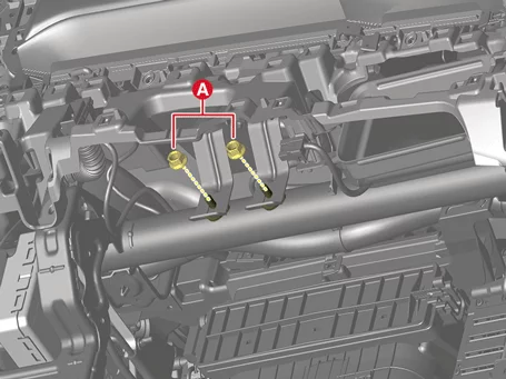
| 8.
|
Remove the Passenger Airbag (PAB) bracket nuts (A).
|
Tightening torque:
3.9 - 5.9 N·m (0.4 - 0.6 kgf·m, 2.9 - 4.3 lb·ft, 34.7 - 52.1 lb·in)
|
|
| 9.
|
Disconnect the Data Connectivity Unit (DCU) connector (A).
|
| 10.
|
Disconnect the Passenger Airbag (PAB) connectors (A).
|
| 11.
|
Remove the crash pad assembly (A) after removing the bolts and nuts.
|
Tightening torque :
6.9 - 10.8 N·m (0.7 - 1.1 kgf·m, 5.1 - 8.0 lb·ft)
|
Driver's Side
Passenger's Side
|
| 1.
|
Install in the reverse order of removal.
|
Crash Pad Cover Removal and Installation
|
The indication below represents the location of a clip or fastener.
|
Center Speaker Grille
| 1.
|
Disconnect the battery negative (-) terminal.
|
| 2.
|
Remove the grille (A).
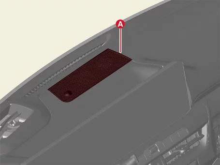
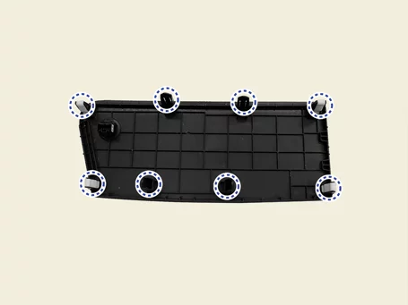
|
| 3.
|
Disconnect the photo sensor connector (A).
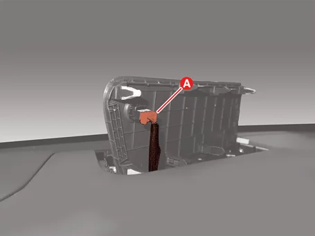
|
Crash Pad Side Cover
| 1.
|
Remove the front door body side weather strip.
(Refer to Front Door - "Front Door Weather Strip")
|
| 2.
|
Remove the cover (A).
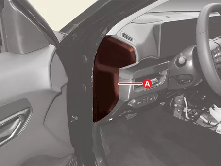
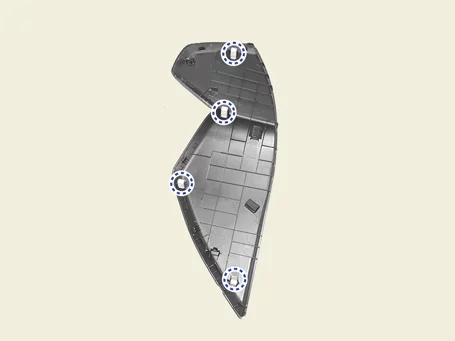
|
Crash Pad Top Cover
| 1.
|
Remove the center speaker grille.
|
| 2.
|
Remove the cover (A) after removing the screws.
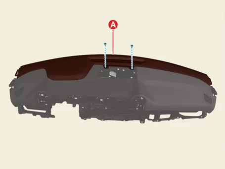
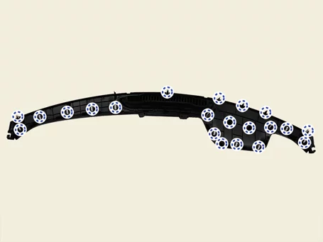
|
| 1.
|
Install in the reverse order of removal.
|
Crash Pad Garnish Removal and Installation
|
The indication below represents the location of a clip or fastener.
|
Crash Pad Lower Garnish [Driver's Side]
| 1.
|
Remove the crash pad lower panel.
(Refer to Crash Pad - "Crash Pad Panel")
|
| 2.
|
Remove the upper steering column shroud panel.
(Refer to Crash Pad - "Steering Column Shroud Panel")
|
| 3.
|
Remove the garnish (A) after removing the screw.
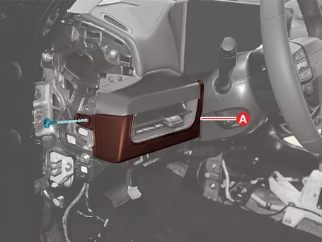
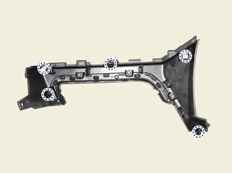
|
Crash Pad Lower Garnish [Passenger's Side]
| 1.
|
Remove the crash pad side cover. [Passenger's side]
(Refer to Crash Pad - "Crash Pad Cover")
|
| 2.
|
Remove the crash pad lower panel.
(Refer to Crash Pad - "Crash Pad Panel")
|
| 3.
|
Remove the upper steering column shroud panel.
(Refer to Crash Pad - "Steering Column Shroud Panel")
|
| 4.
|
Remove the hazard switch cover (A).
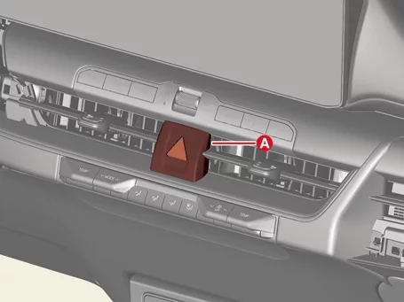
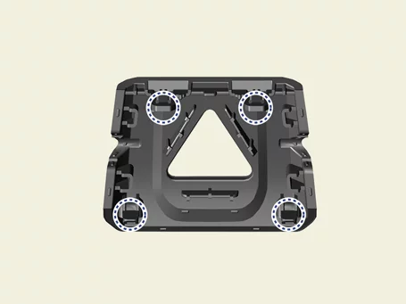
|
| 5.
|
Remove the garnish (A) after removing the screw.
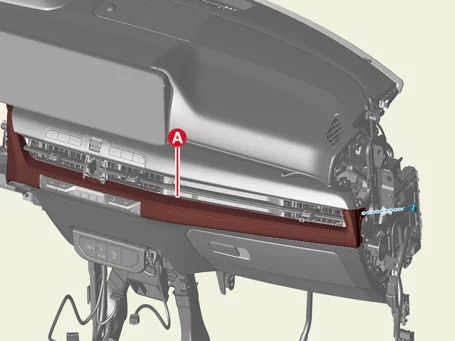
|
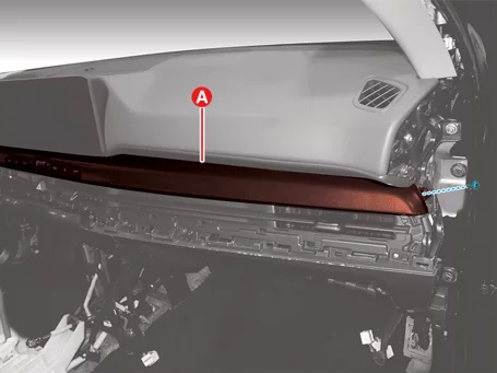
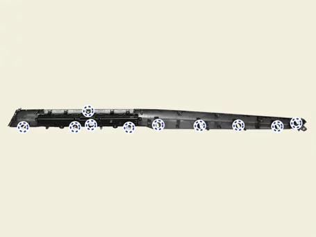
Crash Pad Upper Garnish [Passenger's Side]
| 1.
|
Remove the crash pad lower garnish. [Passenger's side]
|
| 2.
|
Remove the garnish (A) after removing the screw.
|
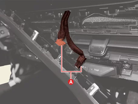
| 3.
|
Disconnect the infotainment keyboard connectors (A).
|
| 1.
|
Install in the reverse order of removal.
|
Crash Pad Panel Removal and Installation
|
The indication below represents the location of a clip or fastener.
|
Crash Pad Lower Panel
| 1.
|
Remove the crash pad side cover. [Driver's Side]
(Refer to Crash Pad - "Crash Pad Cover")
|
| 2.
|
Remove the cowl side trim. [Driver's Side]
(Refer to Interior Trim - "Cowl Side Trim")
|
| 3.
|
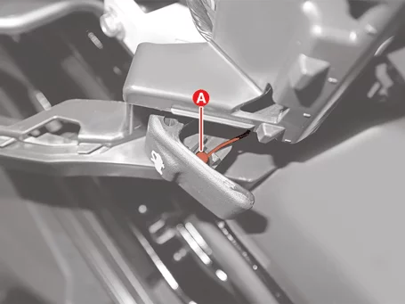
Separate the hood latch cable (A).
|
| 4.
|
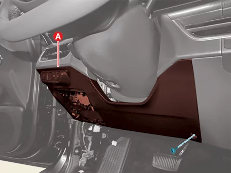
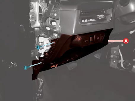
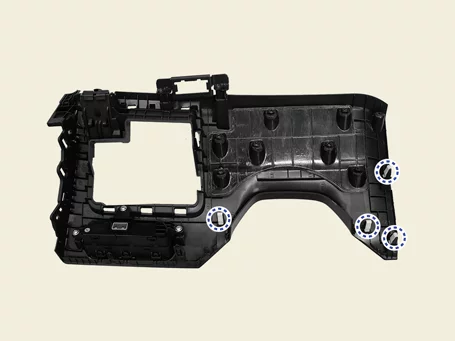
Remove the panel (A) after removing the screws.
|
| 5.
|
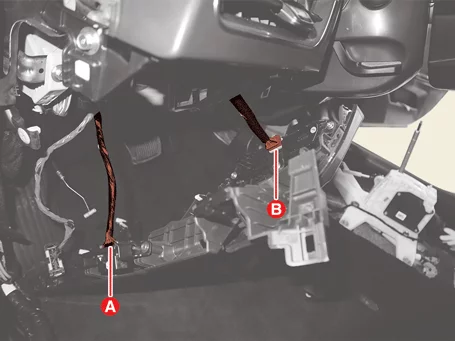
Disconnect the connectors (A, B).
A : Diagnostic tool connector
B : Crash pad switch connector
|
Crash Pad Center Panel
| 1.
|
Remove the floor console assembly.
(Refer to Floor Console - "Floor Console Assembly")
|
| 2.
|
Remove the glove box.
(Refer to Crash Pad - "Glove Box")
|
| 3.
|
Remove the cowl side trim. [Passengers Side]
(Refer to Interior Trim - "Cowl Side Trim")
|
| 4.
|
Remove the heater and air conditioning controller.
(Refer to Heating, Ventilation And Air Conditioning - "Heater
and Air
Conditioning Controller")
|
| 5.
|
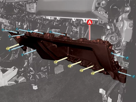
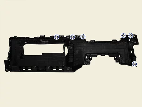
Separate the panel (A) after removing the nuts and screws.
|
Tightening torque :
6.9 - 10.8 N·m (0.7 - 1.1 kgf·m, 5.1 - 8.0 lb·ft)
|
|
| 6.
|
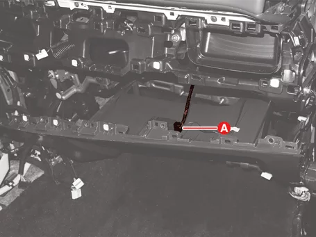
Disconnect the glove box lamp connector (A).
|
Crash Pad Upper Panel [Driver's Side]
| 1.
|
Remove the crash pad top cover.
(Refer to Crash Pad - "Crash Pad Cover")
|
| 2.
|
Remove the crash pad assembly.
(Refer to Crash Pad - "Crash Pad Assembly")
|
| 3.
|
Remove the panel (A) after removing the screws.
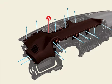
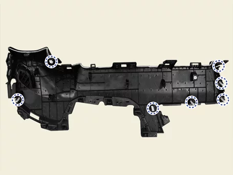
|
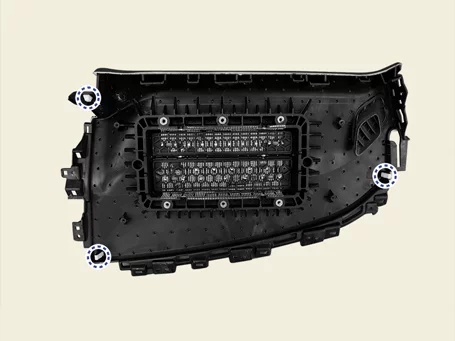
Crash Pad Upper Panel [Passenger's Side]
| 1.
|
Remove the crash upper panel. [Driver's side]
|
| 2.
|
Remove the Passenger Airbag (PAB).
(Refer to Restraint - "Passenger Airbag (PAB)")
|
| 3.
|
Remove the crash pad antenna.
(Refer to Infotainment System - "Antenna")
|
| 4.
|
Remove the panel (A) after removing the bolts and screws.
|
Tightening torque :
6.9 - 10.8 N·m (0.7 - 1.1 kgf·m, 5.1 - 8.0 lb·ft)
|
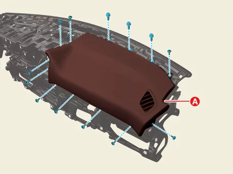
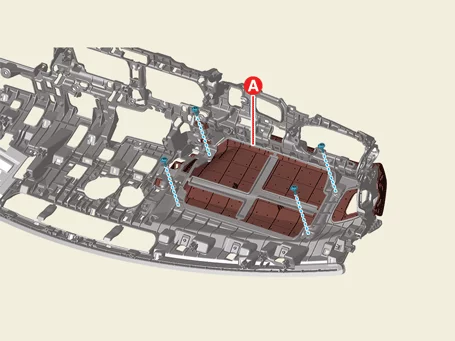
|
| 1.
|
Install in the reverse order of removal.
|
Crash Pad Switch Removal and Installation
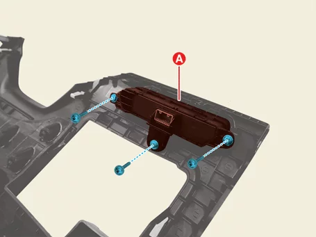
Crash Pad Side Switch
| 1.
|
Remove the crash pad lower panel.
(Refer to Crash Pad - "Crash Pad Panel")
|
| 2.
|
Remove the switch (A) after removing the screws.
|
| 1.
|
Install in the reverse order of removal.
|
Glove Box Removal and Installation
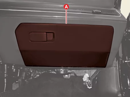
Glove Box
| 1.
|
Open the glove box (A).
|
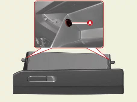
| 2.
|
Remove the glove box after removing the stopper (A).
|
| 1.
|
Install in the reverse order of removal.
|
Steering Column Shroud Panel Removal and Installation
|
The indication below represents the location of a clip or fastener.
|
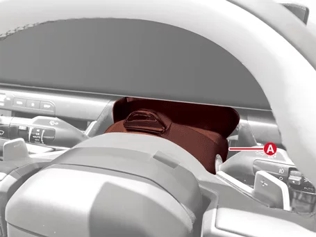
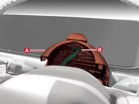
Upper Steering Column Shroud Panel
| 1.
|
Separate the panel (A).
|
| 2.
|
Remove the panel (A) after disconnecting the In Cabin Cam (ICC) camera connector (B).
|
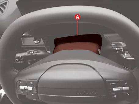
Lower Steering Column Shroud Panel
| 1.
|
Remove the crash pad lower panel.
(Refer to Crash Pad - "Crash Pad Panel")
|
| 2.
|
Separate the upper steering column shroud panel (A).
|
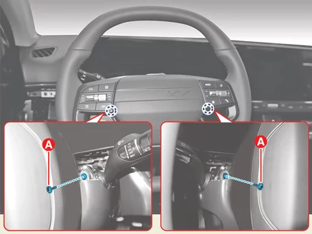
| 3.
|
Turn the steering wheel left and right to remove the screws (A).
|
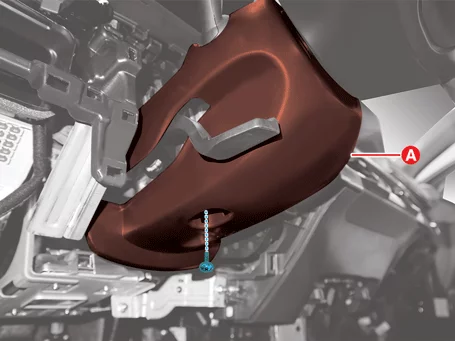
| 4.
|
Remove the panel (A) after removing the screw.
|
| 1.
|
Install in the reverse order of removal.
|