Contents:
Brake Fluid Inspection
| 1.
|
Check the brake fluid level.
|
Be careful as brake fluid can hurt your hands and eyes and damage painted
surfaces. If fluid gets
on your hands or in your eyes, flush the affected area with clean water
immediately.
|
|
Item
|
Recommended
|
Capacity
|
Brake fluid (cc)
|
DOT 4
|
As required
(383 - 423cc)
*Refer to 'MAX - MIN" line on the reservoir tank
|
Brake pedal bushing and brake pedal bolt
|
Chassis grease
(GREASE PDLV-1)
|
As required
|
|
In order to maintain the best braking performance and ABS / ESC performance of the vehicle,
please use
genuine parts that meet the specifications.
(Standard : SAE J1704 DOT-4 LV, ISO4925 CLASS-6, FMVSS
116 DOT-4)
|
| Brake System Bleeding Procedures |
|
Be careful not to brake fluid contact with vehicle paint or human skin. if the brake fluid
spilled, wipe
it with a clean cloth or water immediately. if it touches the body take medical action quickly.
|
Air Bleeding Procedure
This work is to be performed by two people.
|
–
|
Main worker : Bleeds the system by manually opening and closing the bleed screw
and detecting air
coming out of brake lines.
|
|
–
|
Assistant : Brake pedal operation and scanner operation inside the vehicle.
|
|
|
•
|
Do not reuse the drained brake fluid.
|
|
•
|
Always use genuine DOT4 brake Fluid, Using a non-genuine DOT4 brake fluid can
cause corrosion and
decrease the life of the system.
|
|
•
|
Make sure that no dirt or other foreign matter is allowed to contaminate the
brake fluid.
|
|
•
|
Before air bleeding, check all the brake lines for leakage.
|
|
•
|
Check the installation of ABS and ESC control unit.
|
|
| 1.
|
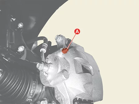
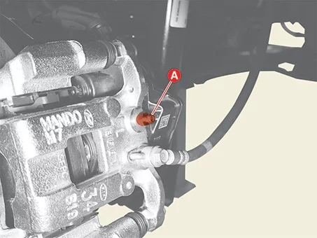
The main worker connects the clear hose to the wheel bleeder screw (A) and sends a signal to
assistant to
depress the brake pedal.
|
| 2.
|
The assistant to pump the brake pedal 2 times with normal brake force and then keep the brake
pedal
depressed.
|
| 3.
|
While the assistant is depressing the brake pedal, remove the bleed screw (A) momentarily to
remove the
air, and then fasten it again.
|
The bleed screw should open and close only 1/4 turn.
|
[Front]
|
Tightening torque :
13.7 - 19.6 N·m (1.4 - 2.0 kgf·m, 10.1 - 14.5 lb·ft)
|
[Rear]
|
Tightening torque :
6.9 - 12.7 N·m (0.7 - 1.3 kgf·m, 5.1 - 9.4 lb·ft, 60.8 - 112.8 lb·in)
|
|
| 4.
|
Repeat the above procedure until no air bubbles appear in the brake fluid.
|
| 5.
|
Perform air bleeding in the following sequence.
 Rear RH →  Rear LH →  Front RH →  Front LH |
| 6.
|
Repeat the procedure one more time.
|
The work order is the same, but the pedals with a very strong and quick
momentary force.
|
|
| 7.
|
Release the brake pedal.
|
| 8.
|
Check the brake pedal stroke.
|
Pedal Stroke :
137.95 mm (5.43 in.)
|
|
Air Bleeding Procedures (For ABS / ESC System)
This procedure should be followed to ensure adequate bleeding of air and filling of the ESC unit, brake lines
and
master cylinder with brake fluid.
This repair is to be performed by two people.
|
–
|
Main worker : Bleeds the system by manually opening and closing the bleed screw
and detecting air
coming out of brake lines.
|
|
–
|
Assistant : Brake pedal operation and scanner operation inside the vehicle.
|
|
| 1.
|
Install a tool that can continuously supply brake fluid to the master cylinder reservoir, or
supply brake
fluid so that the reservoir is always full during operation.
|
•
|
Do not reuse the drained brake fluid.
|
|
•
|
Always use genuine DOT4 brake Fluid, Using a non-genuine DOT4
brake fluid can cause
corrosion and decrease the life of the system.
|
|
•
|
Make sure that no dirt or other foreign matter is allowed to
contaminate the brake fluid.
|
|
•
|
Before air bleeding, check all the brake lines for leakage.
|
|
•
|
Check the installation of ABS and ESC control unit.
|
|
|
| 2.
|
Perform in the below procedure with KDS.
(S/W Management → ABS/ESC → HCU Air Bleeding Mode)
|
Refer to the KDS screen for operating conditions and details.
|
|
Brake Lines, Hoses and Connections Inspection
Visually check for proper installation, chafing, cracks, deterioration and any leakage.
Replace any deteriorated or damaged parts immediately.
Disc Brakes and Pads Inspection
Disc Cleaning Before Inspection
The rust caused by leaving the vehicle unattended for a long period of time is naturally removed under normal
driving conditions. It may affect thickness and runout measurements, please remove rust on the brake disc for
accurate measurements.
| 1.
|
Check the brake disc for rust.
|
| 2.
|
Spray the cleaing solution on rusted surface of disc.
|
Cleaning solution : Water (300 ml) +
Detergent (15 ml)
|
|
Do not use lubricating, oil-based cleaning agents (wax, rust inhibitors). Poor
braking
performance and risk of fire due to pad friction during braking.
|
|
| 3.
|
Drive the vehicle up to 30 MPH and depress the brake up to stop for complete repeat more than 5
cycles.
|
| 4.
|
Clean the brake disc with clean water.
|
| 5.
|
Check the brake disc for rust.
|
| 6.
|
If rust is not removed, repeat the above procedure again.
|
Front Brake Disc Thickness Check
| 1.
|
Remove the front wheel and tires.
(Refer to Suspension System - "Wheel")
|
| 2.
|
Check the brake disc for damage.
|
| 3.
|
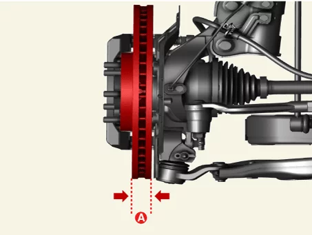
Measure the brake disc thickness (A) and run-out using the micro meter and dial gauge at least
24
locations on the same column along the lines shown in the figure below.
|
Front brake disc thickness (A)
[15", 16" Disc]
Standard : 25 mm (0.98 in.)
Service limit : 23 mm (0.90 in.)
DTV (Disc Thickness Variation) :
Less than 0.015 mm (0.0006 in.) [Circumference direction]
Less than 0.015 mm (0.0006 in.) [Radial direction]
|
|
| 4.
|
If the thickness difference between each measuring part is greater than standard, resurface or
replace
the brake disc.
|
•
|
Resurface the brake disc according to the method of using the
equipment in possession.
|
|
•
|
If the brake disc is less than or equal to the limit, replace
the brake disc with a new
one.
|
|
|
| 5.
|
Install the front wheel and tires.
(Refer to Suspension System - "Wheel")
|
Front Brake Disc Runout Inspection
| 1.
|
Remove the front wheel and tires.
(Refer to Suspension System - "Wheel")
|
| 2.
|
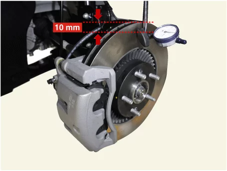
Install the dial gauge perpendicular to the brake disc's external diameter of 10 mm (0.40 in.)
and rotate
the disc to measure the run-out.
|
Brake disc run out
Service Limit : 0.050 mm (0.0019 in.)
|
|
| 3.
|
If the brake disc run-out exceeds the limit, resurface or replace the brake disc.
|
•
|
Resurface the brake disc according to the method of using the
equipment in possession.
|
|
•
|
If the brake disc is less than or equal to the limit, replace
the brake disc with a new
one.
|
|
|
| 4.
|
Install the front wheel and tires.
(Refer to Suspension System - "Wheel")
|
Rear Brake Thickness Check
| 1.
|
Remove the rear wheel and tires.
(Refer to Suspension System - "Wheel")
|
| 2.
|
Check the brake disc for damage.
|
| 3.
|
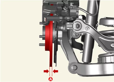
Measure the brake disc thickness (A) and run out using a micrometer and dial gauge. Measure it
at least
24 points.
|
Rear brake disc thickness (A)
[14" Disc]
Standard : 10 mm (0.39 in.)
Service limit : 8.4 mm (0.33 in.)
[15" Disc]
Standard : 10 mm (0.39 in.)
Service limit : 8.0 mm (0.31 in.)
DTV (Disc Thickness Variation) :
Less than 0.015 mm (0.0006 in.) [Circumference direction]
Less than 0.015 mm (0.0006 in.) [Radial direction]
|
|
| 4.
|
If the thickness difference between each measuring part is greater than standard, resurface or
replace
the brake disc.
|
•
|
Resurface the brake disc according to the method of using the
equipment in possession.
|
|
•
|
If the brake disc is less than or equal to the limit, replace
the brake disc with a new
one.
|
|
|
| 5.
|
Install the rear wheel and tires.
(Refer to Suspension System - "Wheel")
|
Rear Brake Disc Runout Inspection
| 1.
|
Remove the rear wheel and tires.
(Refer to Suspension System - "Wheel")
|
| 2.
|
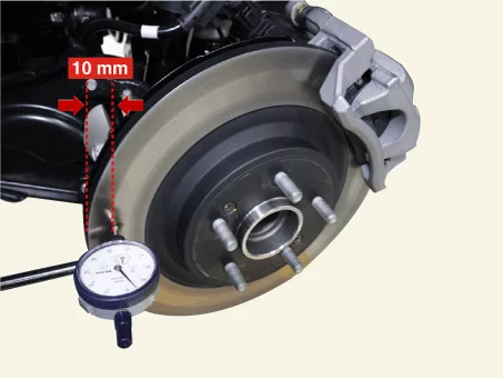
Install the dial gauge perpendicular to the brake disc's external diameter of 10 mm (0.40 in.)
and rotate
the disc to measure the run-out.
|
Brake disc run out
Service limit : 0.055 mm (0.002 in.) or less.
|
|
| 3.
|
If the brake disc run-out exceeds the limit, resurface or replace the brake disc.
|
•
|
Resurface the brake disc according to the method of using the
equipment in possession.
|
|
•
|
If the brake disc is less than or equal to the limit, replace
the brake disc with a new
one.
|
|
|
| 4.
|
Install the rear wheel and tires.
(Refer to Suspension System - "Wheel")
|
| 1.
|
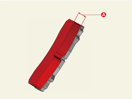
Check brake pad thickness (A). If the thickness is thinner than the limit, replace the brake
pads.
|
Front brake pad thickness
[15", 16" Disc]
Standard : 11.0 mm (0.43 in.)
Service Limit : 2.0 mm (0.07 in.)
|
|
Rear brake pad thickness
[14", 15" Disc]
Standard : 15.0 mm (0.59 in.)
Service Limit : 7.0 mm (0.27 in.)
|
|
| 2.
|
Check that grease is applied to sliding contact points and check the pad and backing metal for
damage.
|
Drive Shafts and Boots Inspection
| 1.
|
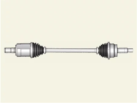
Check the drive shaft boots for loose clamps, cracks, grease leaks, kinks or damage.
|
Steering Gear Rack, Linkage and Boots Inspection
Steering Wheel Play Inspection
| 1.
|
Align the steering wheel straight.
|
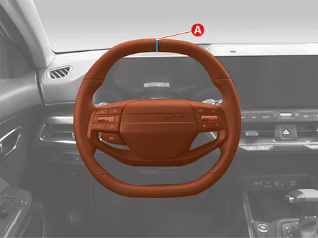
| 2.
|
Mark the center (A) of the steering wheel using masking tape or cable ties, etc.
|
| 3.
|
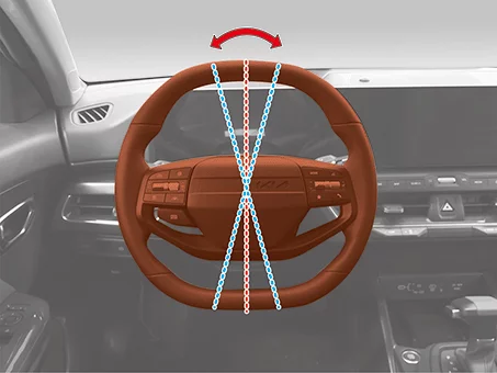
With MDPS power on, lightly turn the steering wheel from side to side to measure the distance
the
steering wheel rotates until the wheel moves.
|
Allowable steering wheel play : 0 - 30
mm ( 0 - 1.18 in.)
|
|
| 4.
|
If the steering wheel play exceeds standard value, inspect the steering column, shaft, and
linkages.
|
Checking Stationary Steering Effort
| 1.
|
Position the vehicle on a level surface and place the steering wheel in the straight ahead
position.
|
| 2.
|
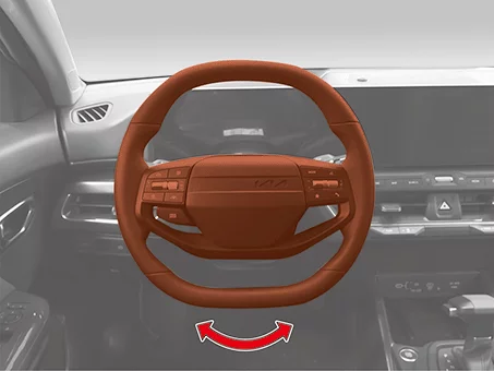
With MDPS powered on, apply a spring scale to the end of the steering wheel and pull the scale
to measure
the force when the steering wheel begins to move.
|
Stationary steering force : Maximum 3.0
kgf (29.0 N, 6.6
lbf)
|
|
| 3.
|
If the measured value exceeds standard value, inspect the steering gear box or MDPS.
|
Suspension Mounting Bolts Inspection
| 1.
|
Visually check the loose mount bolt.
|
Tire (pressure & tread wear) Inspection
| 1.
|
Check the tire pressure.
Tire Size
|
Tire Pressure [kPa (psi)]
|
Front
|
Rear
|
205/55 R16
|
Steel wheel
|
250 (36)
|
230 (33)
|
Aluminum wheel
|
235 (34)
|
215 (31)
|
225/45 R17
|
235/40 R18
|
230 (33)
|
|
| 2.
|
Check the tire tread wear.
(Refer to Suspension System - "Tire")
|
| 3.
|
Check if the wear of tire tread is uneven.
(Refer to Suspension System - "Alignment")
|
Other information:
Kia K4 (CL4) 2025-2026 Service Manual: Driver Attention Warning (DAW)
Driver Attention Warning function
The Driver Attention Warning (DAW) system in your Kia K4 continuously monitors your driving patterns, vehicle stability, and inputs. When the system detects signs of reduced alertness or potential fatigue, the Kia K4 will proactively recommend a rest break to ensure your continued safety on the road.
Leading Vehicle Departure Alert function
The Leading Vehicle Departure Alert (LVDA) is a convenient feature for the Kia K4 that provides an audible and visual notification to the driver when the vehicle ahead of you begins to move from a stationary position, such as at a traffic light or in stop-and-go traffic.
Kia K4 (CL4) 2025-2026 Service Manual: Lighting
The Kia K4 is meticulously engineered with a sophisticated lighting system, featuring a wide array of high-performance lights designed to illuminate both the interior cabin and the vehicle's exterior, ensuring optimal visibility and style.
CAUTION
To preserve the health of your Kia K4 12V battery and prevent accidental discharge, avoid leaving the headlamps or interior dome lights active for an extended period while the engine is not running.