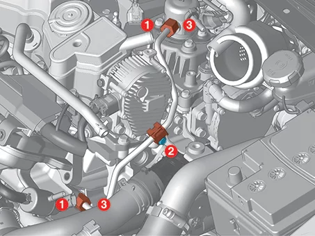
Contents:
Fuel Pressure Test
|
•
|
This video was created using 3D graphics to help understand the vehicle
maintenance manual.
|
|
•
|
There may be some differences from actual vehicles.
|
|
•
|
The location and repair procedures of the parts may vary depending on vehicle
model, model year,
region, and specifications.
|
|
•
|
Check the KDS Guide for detailed information on how to use the KDS.
|
|
•
|
Check the manual for detailed maintenance procedures.
|
|
•
|
Unauthorized reproduction, distribution, or sharing of this video is
prohibited.
|
|
Fuel Pressure Test
Tool Name / Number
|
Illustration
|
Description
|
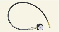
Fuel pressure gauge
09353 - 24100
|
|
Used for measuring the pressure in fuel line
|
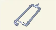
Fuel pressure gauge adapter
0K353 - D4100
|
|
Used for connecting between the delivery pipe and the fuel feed line
|
| 1.
|
Release the residual pressure in fuel line.
(Refer to Fuel Delivery System - "Release Residual Pressure in
Fuel
Line")
|
•
|
Remove the DTC surely with a KDS after the "Release Residual
Pressure in Fuel Line"
procedure since the DTC is occurred when removing the fuel pump
relay.
|
|
•
|
Cover the connection with a clean cloth since the residual fuel
may be released after
"Release Residual Pressure in Fuel Line" procedures.
|
|
|
| 2.
|
Remove the engine cover.
(Refer to Engine Mechanical System - "Engine Cover")
|
| 3.
|
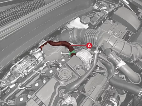
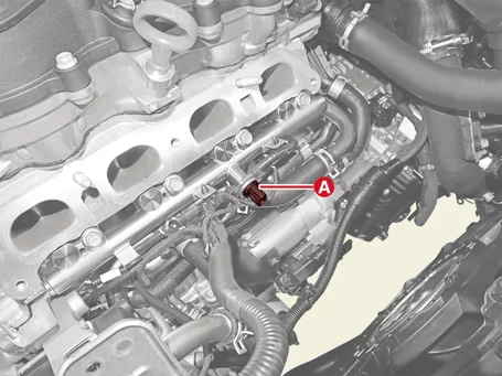
Remove the hose (A) after releasing the clamp.
|
| 4.
|
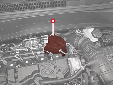
Remove the high pressure fuel pump foam (A).
|
| 5.
|
Install Special Service Tool (SST).
| (1)
|
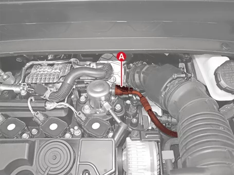
Separate the fuel feed tube (A) from the high pressure fuel pump.
|
•
|
Cover the connection with a clean cloth since
the residual fuel may be released
after "Release Residual Pressure in Fuel Line"
procedures.
|
|
•
|
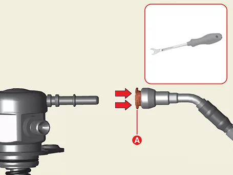
When separating the fuel supply tube, separate
it after pressing the holder (A)
firmly by using the clip remover.
|
|
|
| (2)
|
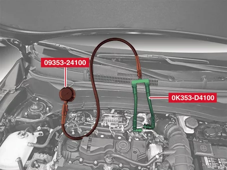
Install SST (09353 - 24100, 0K353 - D4100) for measuring the fuel pressure
between the low
pressure fuel feed tube and the high pressure fuel pump.
|
|
| 6.
|
With the IG ON, check the fuel line and SST connections for the leaks.
|
| 7.
|
Fuel pressure inspection.
| (1)
|
Start the engine and measure the fuel pressure at idle.
|
Fuel pressure [kPa (kg/cm²,
psi)] : 480 - 520
(4.89 - 5.3, 69.62 - 75.42)
|
|
If the fuel pressure is different from the specification,
repair or replace the related
part according to the table below.
|
Fuel
Pressure
|
Suspected
Cause
|
Related
Part
|
Too low
|
Fuel filter clogged
|
Fuel filter
|
Fuel leakage
|
Fuel pressure regulator
|
Too high
|
Fuel pressure regulator valve stuck
|
Fuel pressure regulator
|
|
| (2)
|
Stop the engine, and then check for the change in the fuel pressure gauge
reading.
|
Specification : The
gauge reading should be hold
for about 5 minutes after the engine stops.
|
|
If the fuel pressure should not be maintained, repair or
replace the related part
according to the table below.
|
Fuel
Pressure
(After Engine
Stops)
|
Suspected
Cause
|
Related
Part
|
Fuel pressure drops slowly
|
Leakage on injector
|
Injector
|
Fuel pressure drops immediately
|
Check valve of fuel pump stuck open
|
Fuel pump
|
|
|
| 8.
|
Release the residual pressure in fuel line.
(Refer to Fuel Delivery System - "Release Residual Pressure in
Fuel
Line")
|
Cover the connection with a clean cloth since the residual fuel may be released
after "Release
Residual Pressure in Fuel Line" procedures.
|
|
| 9.
|
Finish test.
| (1)
|
Remove SST from the low pressure fuel feed tube and the low pressure inlet of
high pressure fuel
pump.
|
| (2)
|
Connect the low pressure fuel feed tube and the low pressure inlet of high
pressure fuel pump.
|
|
Description and Operation
|
•
|
This video was created using 3D graphics to help understand the vehicle
maintenance manual.
|
|
•
|
There may be some differences from actual vehicles.
|
|
•
|
The location and repair procedures of the parts may vary depending on vehicle
model, model year,
region, and specifications.
|
|
•
|
Check the KDS Guide for detailed information on how to use the KDS.
|
|
•
|
Check the manual for detailed maintenance procedures.
|
|
•
|
Unauthorized reproduction, distribution, or sharing of this video is
prohibited.
|
|
Fuel System Flow
(Click to play)

Video: Fuel System Flow
Release Residual Pressure in Fuel Line
|
•
|
This video was created using 3D graphics to help understand the vehicle
maintenance manual.
|
|
•
|
There may be some differences from actual vehicles.
|
|
•
|
The location and repair procedures of the parts may vary depending on vehicle
model, model year,
region, and specifications.
|
|
•
|
Check the KDS Guide for detailed information on how to use the KDS.
|
|
•
|
Check the manual for detailed maintenance procedures.
|
|
•
|
Unauthorized reproduction, distribution, or sharing of this video is
prohibited.
|
|
Fuel Line Residual Pressure Releas
(Click to play)
Video: Fuel Line Residual Pressure Release
| Release Residual Pressure in Fuel Line |
|
•
|
Cover the connection with a clean cloth since the residual fuel may be released
after "Release
Residual Pressure in Fuel Line" procedures.
|
|
•
|
Be sure to wear safety gloves and goggles before working.
|
|
| 1.
|
Disconnect the battery negative ( - ) terminal.
|
| 2.
|
Remove the engine room junction box cover (A).
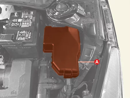
|
| 3.
|
Remove the fuel pump relay (A).
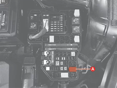
|
| 4.
|
Connect the battery negative ( - ) terminal.
|
| 5.
|
Start the vehicle (idling state) and when the engine stops by itself due to all of the fuel in
the fuel
line is exhausted, turn the IG OFF.
|
| 6.
|
Proceed with the service or repair.
|
| 7.
|
Reinstall / reconnect all components in reverse order of removal. Start engine and confirm
proper
operation, and make sure there are no fuel leaks.
|
After completing, clear DTC(s) using KDS. (the procedure described above will
cause DTC to set)
|
|
Delivery Pipe Components and Components Location
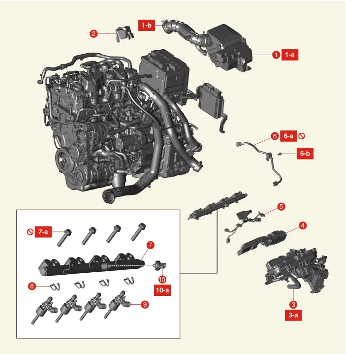
1. Air Cleaner Assembly
1-a. 7.8 - 9.8 N·m
(0.8 -
1.0 kgf·m, 5.8 - 7.2 lb·ft)
1-b. 2.9 - 4.9 N·m (0.3 - 0.5 kgf·m, 2.2 - 3.6 lb·ft, 26.0 - 43.4
lb·in)
2.
High Pressure Fuel Pump Foam
3. Intake Manifold
3-a. 18.6 - 23.5 N·m (1.9 - 2.4 kgf·m, 13.7 -
17.4
lb·ft)
4. Injector Foam
5. Delivery Pipe & Injector Wiring
|
6. High Pressure Fuel Pipe
6-a. 32.4 - 35.3
N·m
(3.3 - 3.6 kgf·m, 23.9 - 26.0 lb·ft)
6-b. 9.8 - 11.8 N·m (1.0 - 1.2 kgf·m, 7.2 - 8.7 lb·ft)
7.
Delivery
Pipe
7-a. 24.5 - 27.5 N·m (2.5 - 2.8 kgf·m, 18.1 - 20.3 lb·ft)
8. Clip
9. Injector
10.
Rail
Pressure Sensor (RPS)
10-a. 30.4 - 34.3 N·m (3.1 - 3.5 kgf·m, 22.4 - 25.3 lb·ft)
|
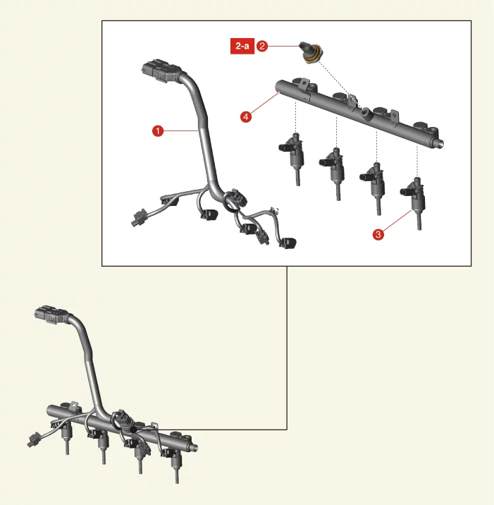
1. Wiring
2. Rail Pressure Sensor
(RPS)
2-a.
30.4 - 34.3 N·m (3.1 - 3.5 kgf·m, 22.4 - 25.3 lb·ft)
|
3. Injector
4. Delivery Pipe
|
Delivery Pipe Removal and Installation
|
Since there is a risk of injury due to high pressure fuel leakage, do not perform any work
right after
the engine is stopped.
|
|
Cover the connection with a clean cloth since the residual fuel may be released after "Release
Residual
Pressure in Fuel Line" procedures.
|
| 1.
|
Release the residual pressure in fuel line.
(Refer to Fuel Delivery System - "Release Residual Pressure in
Fuel
Line")
|
| 2.
|
Remove the intake manifold.
(Refer to Engine Mechanical System - "Intake Manifold")
|
| 3.
|
Remove the high pressure fuel pipe.
(Refer to Fuel Delivery System - "Fuel Line")
|
| 4.
|
Remove the injector foam (A).
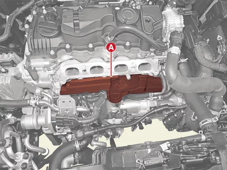
|
| 5.
|
Separate the delivery pipe and injector wiring connector (A) by pulling it in the direction of
the arrow
from the return hose bracket.
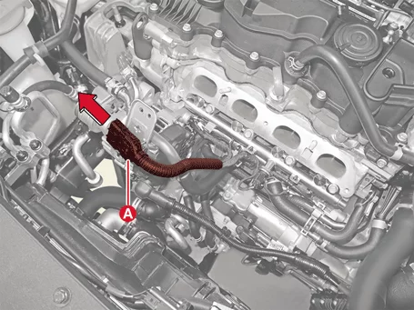
|
| 6.
|
Disconnect the Engine Coolant Temperature Sensor (ECTS) #1 connector (A).
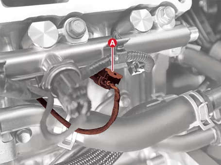
|
| 7.
|
Disconnect the ECTS #2 connector (A).
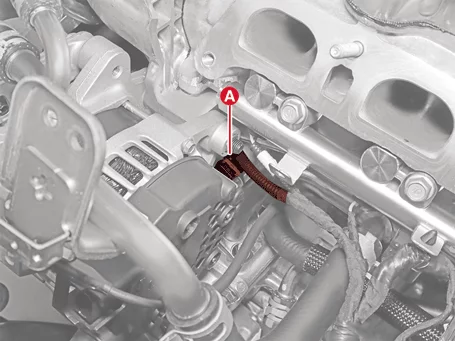
|
| 8.
|
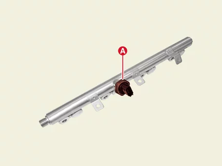
Remove the delivery pipe and injector assembly (A) after removing the bolts.
|
Tightening torque :
24.5 - 27.5 N·m (2.5 - 2.8 kgf·m, 18.1 - 20.3 lb·ft)
|
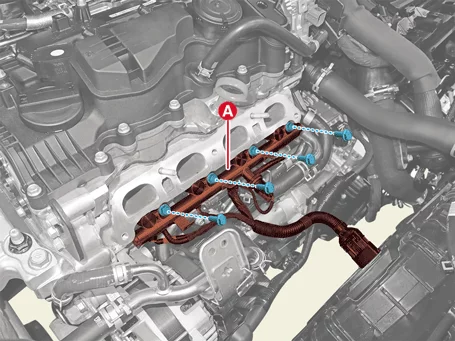
|
| 9.
|
Disconnect the injector connectors (A) and Rail Pressure Sensor (RPS) connector (B).
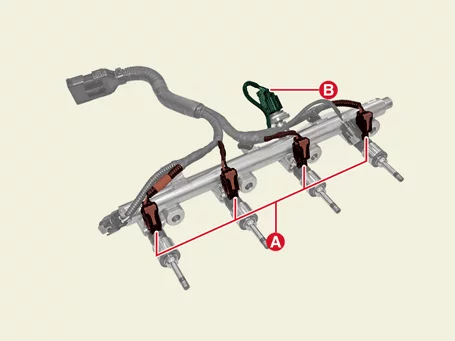
|
| 10.
|
Remove the delivery pipe and injector wiring (A) after removing the fixing clips (B).
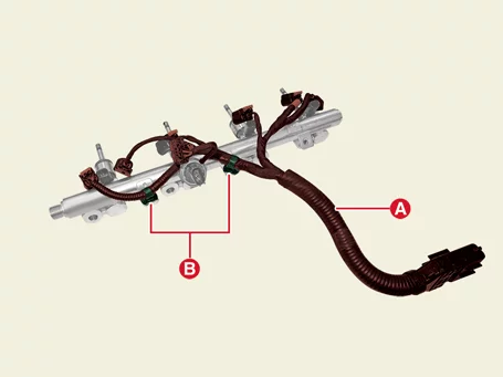
|
| 11.
|
Remove the injectors (A) from the delivery pipe.
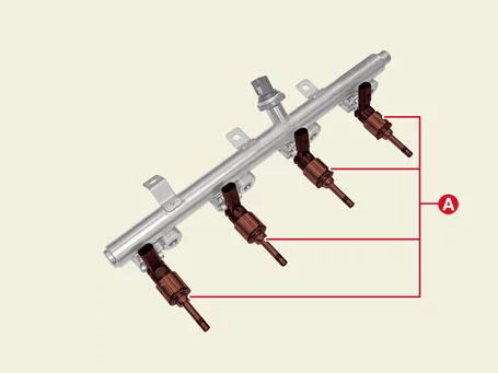
|
| 12.
|
Remove the RPS (A) from the delivery pipe.
|
Tightening torque :
30.4 - 34.3 N·m (3.1 - 3.5 kgf·m, 22.4 - 25.3 lb·ft)
|
|
| 1.
|
Install in the reverse order of removal.
|
•
|
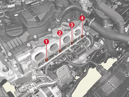
Install the delivery pipe to the specified torque.
|
|
•
|
When installing the delivery pipe, pre-tighten the bolts and
tighten them in order.
|
Tightening
order : 2→3→1→4
|
|
|
•
|
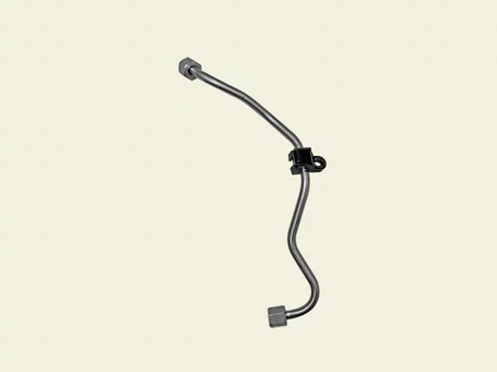
Replace the high pressure fuel pipe with a new one. (Do not
reuse)
|
|
|
Filler-Neck Assembly Components and Components Location
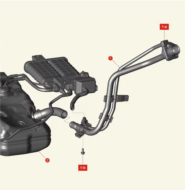
1. Filler-neck Assembly
1-a. 7.8 - 11.8 N·m
(0.8 -
1.2 kgf·m, 5.8 - 8.7 lb·ft)
1-b. 7.8 - 11.8 N·m (0.8 - 1.2 kgf·m, 5.8 - 8.7 lb·ft)
|
2. Fuel Tank
|
Filler-Neck Assembly Removal and Installation
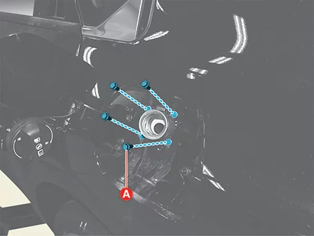
| 1.
|
Remove the filler-neck screws (A) after opening the fuel filler cap.
|
Tightening torque :
7.8 - 11.8 N·m (0.8 - 1.2 kgf·m, 5.8 - 8.7 lb·ft)
|
|
| 2.
|
Remove the left side rear wheel guard.
(Refer to Body - "Wheel Guard")
|
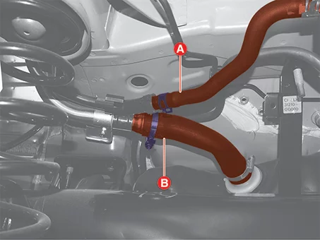
| 3.
|
Remove the ventilation hose (A) and fuel filler hose (B).
|
Tightening torque :
4.2 - 4.8 N·m (0.43 - 0.49 kgf·m, 3.1 - 3.5 lb·ft, 37.3 - 42.5 lb·in)
|
|
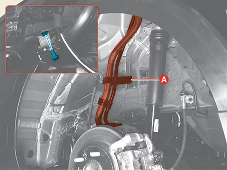
| 4.
|
Remove the filler-neck assembly (A) after removing the bolt and fastener.
|
Tightening torque :
7.8 - 11.8 N·m (0.8 - 1.2 kgf·m, 5.8 - 8.7 lb·ft)
|
|
| 1.
|
Install in the reverse order of removal.
|
Install the filler-neck assembly to the specified torque.
|
|
Fuel Filter Components and Components Location
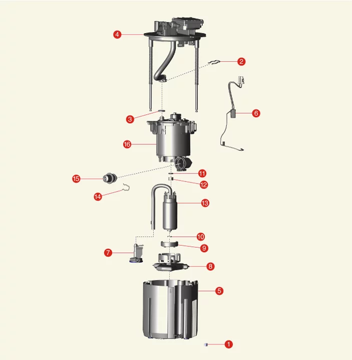
1. Stopper
2. Clip
3. O-Ring
4. Fuel
Pump
Plate Assembly
5. Reservoir Cup
6. Pump Wiring
7. Assist Pump
8. Pump Filter
|
9. Fuel Pump Packing
10. O-Ring
11.
O-Ring
12. Spacer
13. Fuel Pump
14. Clip
15. Fuel Pressure Regulator
16. Fuel
Filter
|
Fuel Filter Removal and Installation
| 1.
|
Remove the fuel pump module.
(Refer to Fuel Delivery System - "Fuel Pump Module")
|
| 2.
|
Disconnect the fuel pump connector (A) and fuel sender connector (B).
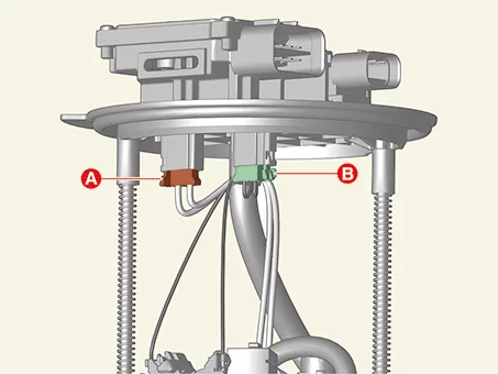
|
| 3.
|
Separate the fuel feed hose (A) after removing the clip (B).
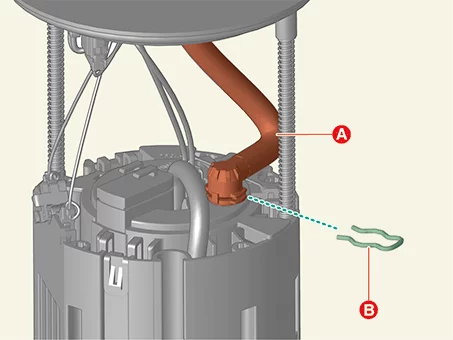
|
| 4.
|
Remove the stopper (A) from the fuel pump plate assembly.
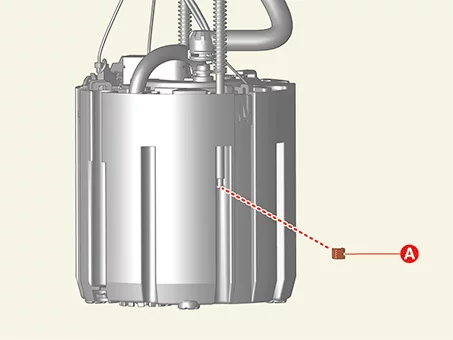
|
| 5.
|
Remove the fuel pump plate assembly (A) and O-ring (B).
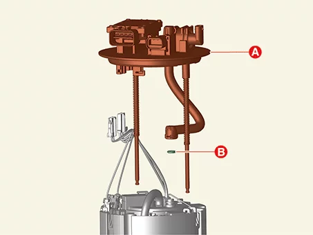
|
| 6.
|
Remove the reservoir cup (A) by releasing the fixing clips.
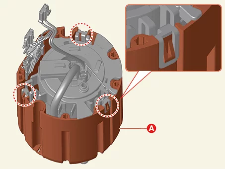
|
| 7.
|
Remove the wiring (A) from the fuel filter after disconnecting the fuel pump connector and
ground.
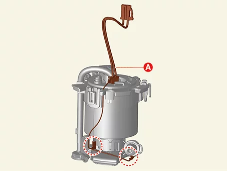
|
| 8.
|
Remove the assist pump (A) after releasing the clamp.
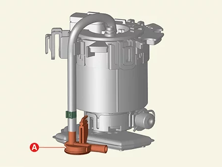
|
| 9.
|
Remove the pump filter (A) by releasing the fixing clips.
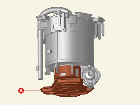
|
| 10.
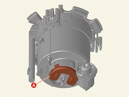
|
Remove the fuel pump packing (A).
|
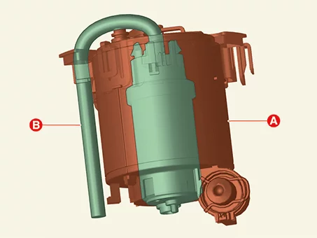
| 11.
|
Separate the fuel filter (A) and fuel pump (B).
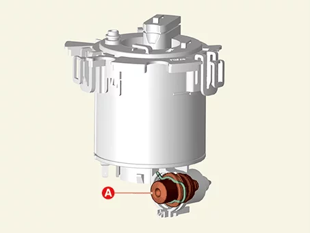
|
| 12.
|
Remove the fuel pressure regulator (A) from the fuel filter.
|
| 1.
|
Install in the reverse order of removal.
|
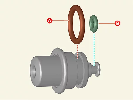
•
|
Be careful not to miss the O-ring (A, B) when installing the
fuel pressure regulator.
|
|
•
|
Be careful not to miss the O-ring (A) and spacer (B) when
installing the fuel pump.
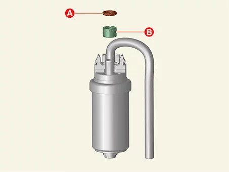
|
|
•
|
Fix the clip certainly when assembling the fuel pump hose
clamp.
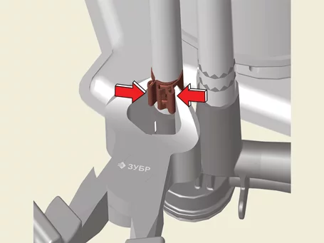
|
|
•
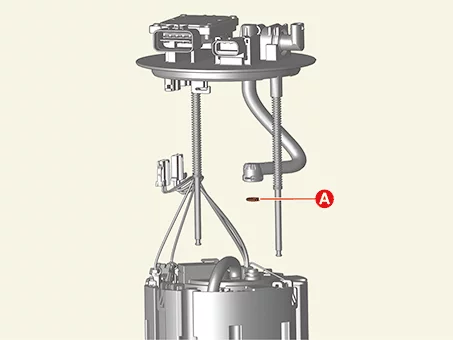
|
Be careful not to miss the O-ring (A) when assembling the plate
cover assembly.
|
|
|
| 2.
|
Check for fuel leaks after installation.
|
Fuel Line Components and Components Location
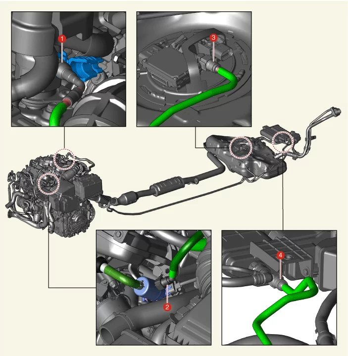
1. Fuel Feed Tube (Engine Side)
2. Vapor
Hose
(Engine Side)
|
3. Fuel Feed Tube (Fuel Tank Side)
4. Vapor
Tube
(Canister ↔ Purge Control Solenoid Valve (PCSV))
|
Fuel Line Removal and Installation
|
Since there is a risk of injury due to high pressure fuel leakage, do not perform any work
right after
the engine is stopped.
|
|
Cover the connection with a clean cloth since the residual fuel may be released after "Release
Residual
Pressure in Fuel Line" procedures.
|
Fuel Feed Tube & Vapor Tube
| 1.
|
Release the residual pressure in fuel line.
(Refer to Fuel Delivery System - "Release Residual Pressure in
Fuel
Line")
|
| 2.
|
Remove the battery.
(Refer to Engine Electrical System - "Battery")
|
| 3.
|
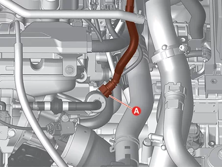
Separate the vapor tube (A).
|
| 4.
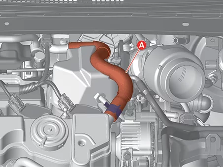
|
Separate the breather hose (A) after releasing the clamp.
|
| 5.
|
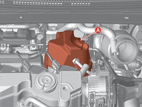
Remove the high pressure fuel pump foam (A).
|
| 6.
|
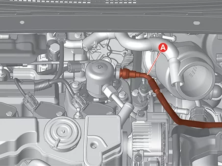
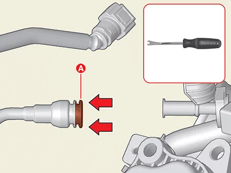
Separate the fuel feed tube (A).
|
•
|
Cover the connection with a clean cloth since the residual fuel
may be released after
"Release Residual Pressure in Fuel Line" procedures.
|
|
•
|
When separating the fuel supply tube, separate it after
pressing the holder (A) firmly by
using the clip remover.
|
|
|
| 7.
|
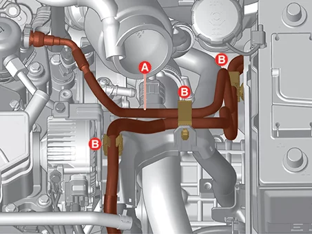
Remove the fuel lines (A) after removing the holders (B).
|
| 8.
|
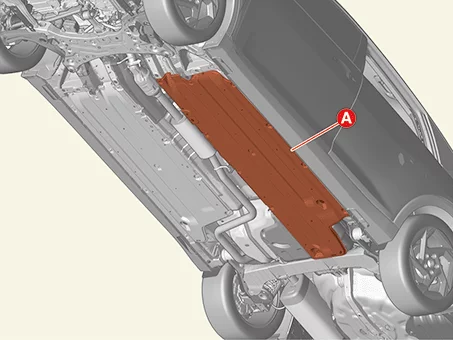
Remove the floor under cover (A).
|
Tightening torque :
7.8 - 11.8 N·m (0.8 - 1.2 kgf·m, 5.8 - 8.7 lb·ft)
|
|
| 9.
|
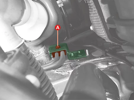
Remove the holder (A) from the bracket for separating the fuel line.
|
| 10.
|
Remove the fuel tank.
(Refer to Fuel Delivery System - "Fuel Tank")
|
| 11.
|
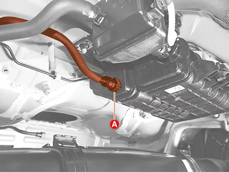
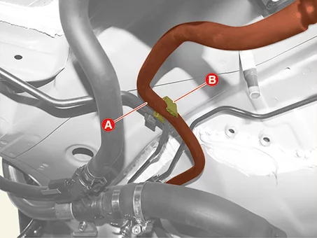
Disconnect the purge hose (A) and separate the purge hose from the holder (B).
|
| 12.
|
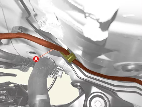
Separate the purge hose (A) from the holder.
|
| 13.
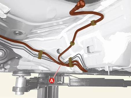
|
Separate the fuel lines (A) from the holders (B).
|
| 14.
|
Remove the fuel line protector (A).
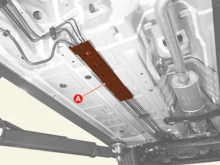
|
| 15.
|
Remove the fuel lines (A) from the holder.
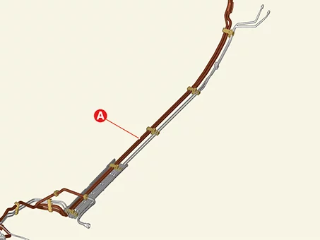
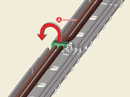
|
High Pressure Fuel Pipe
| 1.
|
Release the residual pressure in fuel line.
(Refer to Fuel Delivery System - "Release Residual Pressure in
Fuel
Line")
|
| 2.
|
Disconnect the battery negative ( - ) terminal.
|
| 3.
|
Remove the engine cover.
(Refer to Engine Mechanical System - "Engine Cover")
|
| 4.
|
Remove the air cleaner.
(Refer to Engine Mechanical System - "Air Cleaner")
|
| 5.
|
Separate the vapor tube (A).
|
| 6.
|
Separate the breather hose (A) after releasing the clamp.
|
| 7.
|
Remove the high pressure fuel pump foam (A).
|
| 8.
|
Separate the fuel feed tube (A).
|
•
|
Cover the connection with a clean cloth since the residual fuel
may be released after
"Release Residual Pressure in Fuel Line" procedures.
|
|
•
|
When separating the fuel supply tube, separate it after
pressing the holder (A) firmly by
using the clip remover.
|
|
|
| 9.
|
Remove the fuel lines (A) after removing the holders (B).
|
| 10.
|
Disconnect the extension connector (A).
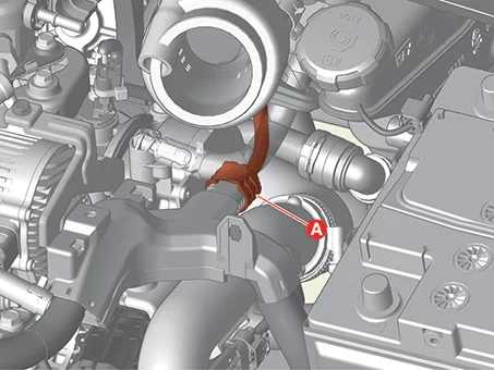
|
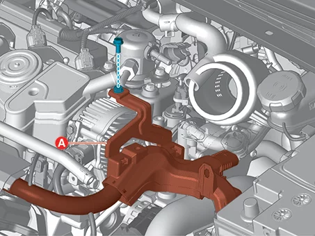
| 11.
|
Separate the wiring protector and bracket (A) after removing the bolt.
|
Tightening torque :
9.8 - 11.8 N·m (1.0 - 1.2 kgf·m, 7.2 - 8.7 lb·ft)
|
|
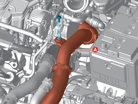
| 12.
|
Separate the intercooler inlet pipe (A) after removing the bolt.
|
Tightening torque :
18.6 - 23.5 N·m (1.9 - 2.4 kgf·m, 13.7 - 17.4 lb·ft)
|
|
| 13.
|
Remove the high pressure fuel pipe.
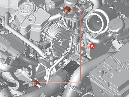
| (1)
|
Loosen the flange nuts (A).
|
Tightening torque :
32.4 - 35.3 N·m (3.3 - 3.6 kgf·m, 23.9 - 26.0 lb·ft)
|
|
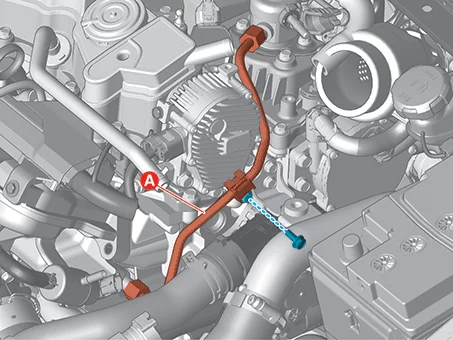
| (2)
|
Remove the high pressure fuel pipe (A) after removing the holder bolt.
|
Tightening torque :
9.8 - 11.8 N·m (1.0 - 1.2 kgf·m, 7.2 - 8.7 lb·ft)
|
|
|
Be careful not to get foreign matter into the delivery pipe and the high
pressure fuel
pump/connection area.
|
|
| 1.
|
Install in the reverse order of removal.
|
•
|
Install the fuel line and high pressure fuel pipe to the
specified torque.
|
|
•
|
Replace the high pressure fuel pipe with a new one. (Do not
reuse)
|
|
|
| 2.
|
Check for fuel leaks after installation.
|
Fuel Pressure Regulator Components and Components Location
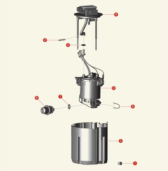
1. Stopper
2. Clip
3. O-Ring
4. Fuel
Pump
Plate Assembly
|
5. Reservoir Cup
6. Clip
7. O-Ring
8.
Fuel
Pressure Regulator
9. Fuel Filter
|
Fuel Pressure Regulator Removal and Installation
| 1.
|
Remove the fuel pump module.
(Refer to Fuel Delivery System - "Fuel Pump Module")
|
| 2.
|
Disconnect the fuel pump connector (A) and fuel sender connector (B).
|
| 3.
|
Separate the fuel feed hose (A) after removing the clip (B).
|
| 4.
|
Remove the stopper (A) from the fuel pump plate assembly.
|
| 5.
|
Remove the fuel pump plate assembly (A) and O-ring (B).
|
| 6.
|
Remove the reservoir cup (A) by releasing the fixing clips.
|
| 7.
|
Separate the wiring (A) from the fuel filter.
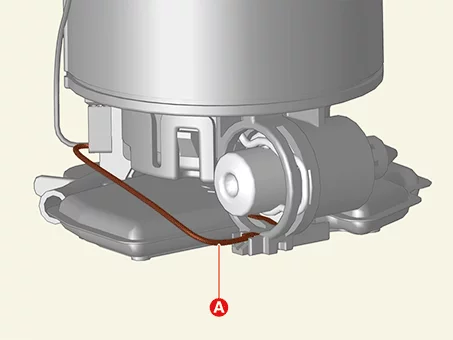
|
| 8.
|
Remove the fuel pressure regulator (A) after removing the fixing clip.
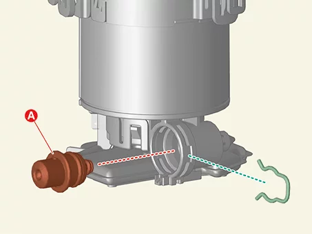
|
| 1.
|
Install in the reverse order of removal.
|
•
|
Be careful not to miss the O-ring (A, B) when installing the
fuel pressure regulator.
|
|
•
|
Be careful not to miss the O-ring (A) when assembling the plate
cover assembly.
|
|
|
| 2.
|
Check for fuel leaks after installation.
|
Fuel Pressure Sensor (FPS) Specifications
Item
|
Specification
|
Operating voltage (V)
|
4.75 - 5.25
|
Rated current (mA)
|
Maximum 10
|
Pressure characteristics
Item
|
Specification
|
Pressure
|
bar
|
0.5
|
6
|
11
|
MPa
|
0.05
|
0.6
|
1.1
|
psi
|
7.1
|
86.7
|
159.3
|
Output voltage (V)
|
0.3
|
2.5
|
4.5
|
Fuel Pressure Sensor (FPS) Components and Components Location
| Components and Components Location |
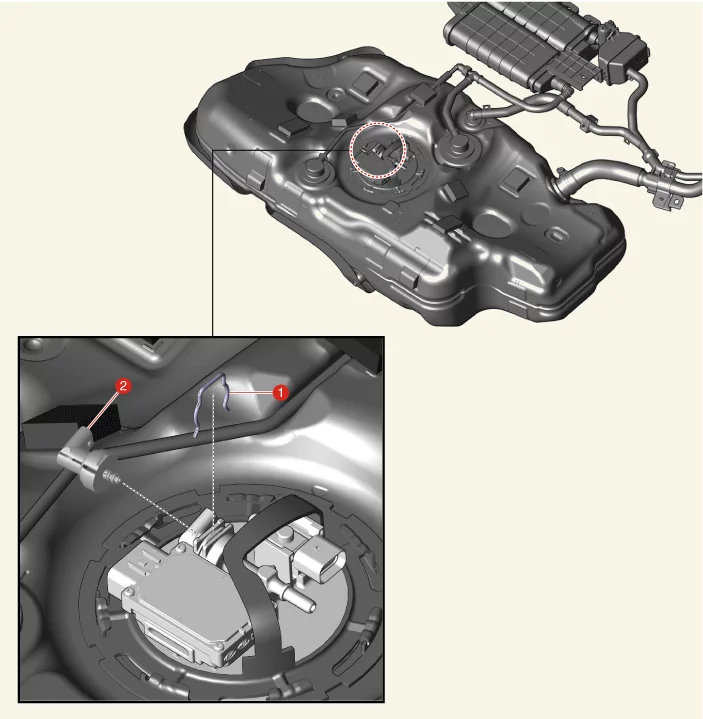
1. Fixing Clip
|
2. Fuel Pressure Sensor (FPS)
|
Fuel Pressure Sensor (FPS) Description and Operation
|
•
|
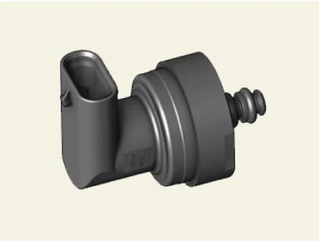
Fuel Pressure Sensor (FPS) is mounted on top of the low pressure fuel pump plate.
|
|
•
|
FPS measures the low pressure fuel pressure and sends it to Fuel Pump Control Module (FPCM)
|
|
•
|
FPCM controls the low pressure fuel pump based on FPS information
|
Fuel Pressure Sensor (FPS) On Vehicle Inspection
| 1.
|
The fuel delivery system can be more quickly diagnosed for problems with the KDS. (Refer to
"DTC guide")
| (1)
|
Self Diagnosis : Inspect the Diagnostic Trouble Code (DTC) with the KDS
(Refer to DTC guide when fault code is found)
|
| (2)
|
Data Analysis : Checking the system input/output data state
(Data Analysis → System Selection → Engine)
Item
|
Specification
|
Pressure
|
bar
|
0.5
|
6
|
11
|
MPa
|
0.05
|
0.6
|
1.1
|
psi
|
7.1
|
86.7
|
159.3
|
Output voltage (V)
|
0.3
|
2.5
|
4.5
|
|
|
•
|
If the fuel pressure sensor becomes faulty, the fail safe mode
will be activated. As the
current value increases, the fuel pressure will be increased,
and the low pressure fuel
pressure will be maintained by the increased fuel pressure. The
output voltage is fixed at
12 V.
|
|
•
|
Refer to the KDS screen for operating conditions and details
|
|
|
Fuel Pressure Sensor (FPS) Removal and Installation
| 1.
|
Release the residual pressure in fuel line.
(Refer to Fuel Delivery System - "Release Residual Pressure in
Fuel
Line")
|
| 2.
|
Disconnect the battery negative ( - ) terminal.
|
| 3.
|
Remove the rear seat assembly.
(Refer to Body - "Rear Seat Assembly")
|
| 4.
|
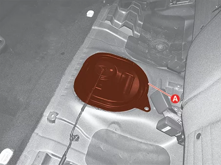
Remove the fuel pump service cover (A).
|
| 5.
|
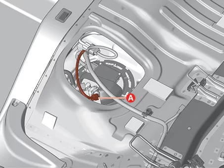
Disconnect the Fuel Pressure Sensor (FPS) connector (A).
|
| 6.
|
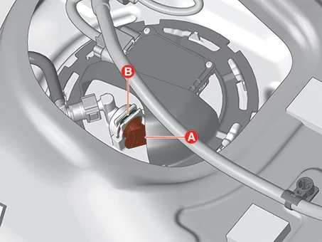
Remove the FPS (A) after removing the fixing clip.
|
| 1.
|
Install in the reverse order of removal.
|
Fuel Pump Components and Components Location
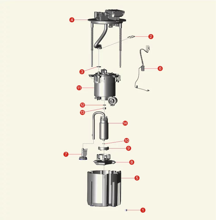
1. Stopper
2. Clip
3. O-Ring
4. Fuel
Pump
Plate Assembly
5. Reservoir Cup
6. Pump Wiring
7. Assist Pump
|
8. Pump Filter
9. Fuel Pump Packing
10.
O-Ring
11. Fuel Filter
12. O-Ring
13. Spacer
14. Fuel Pump
|
Fuel Pump Removal and Installation
|
•
|
This video was created using 3D graphics to help understand the vehicle
maintenance manual.
|
|
•
|
There may be some differences from actual vehicles.
|
|
•
|
The location and repair procedures of the parts may vary depending on vehicle
model, model year,
region, and specifications.
|
|
•
|
Check the KDS Guide for detailed information on how to use the KDS.
|
|
•
|
Check the manual for detailed maintenance procedures.
|
|
•
|
Unauthorized reproduction, distribution, or sharing of this video is
prohibited.
|
|
Fuel Pump Removal
(Click to play)
Video: Fuel Pump Removal
| 1.
|
Remove the fuel pump module.
(Refer to Fuel Delivery System - "Fuel Pump Module")
|
| 2.
|
Disconnect the fuel pump connector (A) and fuel sender connector (B).
|
| 3.
|
Separate the fuel feed hose (A) after removing the clip (B).
|
| 4.
|
Remove the stopper (A) from the fuel pump plate assembly.
|
| 5.
|
Remove the fuel pump plate assembly (A) and O-ring (B).
|
| 6.
|
Remove the reservoir cup (A) by releasing the fixing clips.
|
| 7.
|
Remove the wiring (A) from the fuel filter after disconnecting the fuel pump connector and
ground.
|
| 8.
|
Remove the assist pump (A) after releasing the clamp.
|
| 9.
|
Remove the pump filter (A) by releasing the fixing clips.
|
| 10.
|
Remove the fuel pump packing (A).
|
| 11.
|
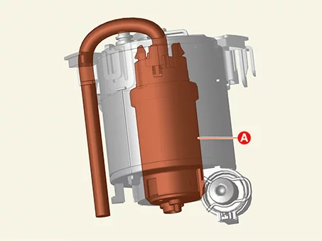
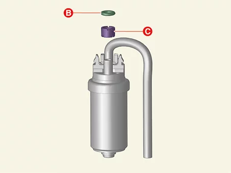
Remove the O-ring (B) and spacer (C) after removing the fuel pump & tube (A).
|
| 1.
|
Install in the reverse order of removal.
|
•
|
Be careful not to miss the O-ring (A) and spacer (B) when
installing the fuel pump.
|
|
•
|
Fix the clip certainly when assembling the fuel pump hose
clamp.
|
|
•
|
Be careful not to miss the O-ring (A) when assembling the plate
cover assembly.
|
|
|
| 2.
|
Check for fuel leaks after installation.
|
Fuel Pump Control Module (FPCM) Components and Components Location
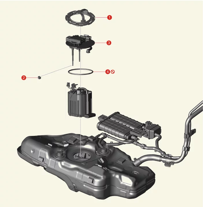
1. Plate Cover
2. Stopper
|
3. Fuel Pump Plate Assembly
4. O-Ring
|
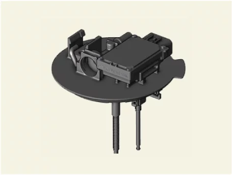
Fuel Pump Control Module (FPCM) Description and Operation
|
•
|
Installed on the fuel tank, the Fuel Pump Control Module (FPCM) controls the pump motor mounted
inside
the low pressure fuel pump.
|
|
•
|
The actual pressure measured by the pressure sensor and the target pressure are compared to
control the
voltage applied to the fuel pump in real time.
|
|
•
|
When fuel pump/controller/pressure sensor/system are diagnosed as faults, the information is
transmitted
to Engine Control Module (ECM).
|
|
•
|
If there is fault diagnosis, the fuel pump will be activated forcibly by the mode that has been
set.
|
Fuel Pump Control Module (FPCM) Troubleshooting
Diagnostic Item
|
Detecting Conditions
|
Operation of the controller in case of fault
|
Detecting Item
|
Time (s)
|
1
|
Low pressure pump disconnection
|
Motor current < 0.4 A
|
2
|
Normal operation
|
2
|
Low pressure pump over current
|
Motor current > 40 A
|
0.2
|
Motor 0.2 sec ON, 0.3 sec OFF (Repeat)
|
Motor current > 15 A
|
20
|
3
|
Pressure sensor disconnection
|
Pressure sensor output voltage < 0.3 V
|
10
|
Fixed control for the 12 V motor
|
4
|
Pressure sensor short circuit
|
Pressure sensor output voltage ≥ 4.75 V
|
2
|
5
|
Pressure sensor signal error
|
Pressure sensor signal > 100 kPa
|
10
|
6
|
Pressure sensor output voltage high
|
4.75 V > Pressure sensor output voltage > 3.7 V
|
2
|
7
|
Low pressure pump control circuit error
|
Pressure sensor supply voltage < 4.75 or Pressure sensor supply voltage > 5.25 V
|
2
|
8
|
Low pressure pump system error
|
Target voltage > 100 kPa
|
5
|
9
|
CAN Time out
|
CAN message not received
|
0.5
|
Fixed control for 5 bar
|
Fuel Pump Control Module (FPCM) On Vehicle Inspection
| 1.
|
The fuel delivery system can be more quickly diagnosed for problems with the KDS. (Refer to
"DTC guide")
| (1)
|
Self Diagnosis : Inspect the Diagnostic Trouble Code (DTC) with the KDS
(Refer to DTC guide when fault code is found)
|
| (2)
|
Data Analysis : Checking the system input/output data state
(Data Analysis → System Selection → Engine)
|
| (3)
|
Actuation test : Checking the system operation condition
(Data Analysis → Engine → Actuation test → Fuel Pump Control(1st Stage))
|
|
Refer to the KDS screen for operating conditions and details
|
|
Fuel Pump Control Module (FPCM) Removal and Installation
|
If necessary to replace the Fuel Pump Control Module (FPCM), replace the fuel pump plate
assembly.
|
| 1.
|
Remove the Fuel Tank Pressure Sensor (FTPS).
(Refer to Emission Control System - "Fuel Tank Pressure Sensor
(FTPS)")
|
| 2.
|
Remove the Fuel Pressure Sensor (FPS).
(Refer to Fuel Delivery System - "Fuel Pressure Sensor
(FPS)")
|
| 3.
|
Remove the fuel pump module.
(Refer to Fuel Delivery System - "Fuel Pump Module")
|
| 4.
|
Disconnect the fuel pump connector (A) and fuel sender connector (B).
|
| 5.
|
Separate the fuel feed hose (A) after removing the clip (B).
|
| 6.
|
Remove the stopper (A) from the fuel pump plate assembly.
|
| 7.
|
Remove the fuel pump plate assembly (A) and O-ring (B).
|
| 1.
|
Install in the reverse order of removal.
|
•
|
Be careful not to get foreign matter into the fuel tank.
|
|
•
|
Be careful not to miss the O-ring (A) when assembling the plate
cover assembly.
|
|
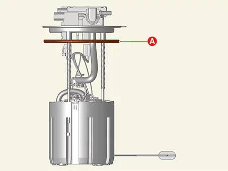
•
|
Be careful not to miss the O-ring (A) when assembling the fuel
pump module.
|
|
|
| 2.
|
Check for fuel leaks after installation.
|
Fuel Pump Module Specification
Item
|
Specification
|
Voltage (V)
|
13.5
|
Operating current (A)
|
Maximum 8.5
|
Fuel pressure [kPa (kgf / cm², psi)]
|
480 - 520 (4.89 - 5.3, 69.62 - 75.42)
|
Fuel Pump Module Components and Components Location
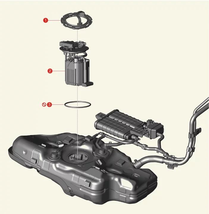
1. Plate Cover
|
2. Fuel Pump Module
3. O-ring
|
Fuel Pump Module On Vehicle Inspection
| 1.
|
The fuel delivery system can be more quickly diagnosed for problems with the KDS. (Refer to
"DTC guide")
| (1)
|
Self diagnosis : Inspect the Diagnostic Trouble Code (DTC) with the KDS
(Refer to DTC guide when fault code is found)
|
| (2)
|
Data analysis : Checking the system input/output data state
(Data Analysis → System Selection → Engine)
|
| (3)
|
Actuation test : Checking the system operation condition
(Data Analysis → System Selection → Engine → Actuation test → Fuel Pump
Control(1st Stage))
|
|
Refer to the KDS screen for operating conditions and details
|
|
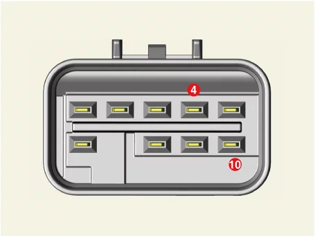
| 1.
|
Disconnect the Fuel Pump Control Module (FPCM) connector.
(Refer to Fuel Pump Module - "Removal and Installation")
|
| 2.
|
Check fuel pump operation by connecting power to terminal 4 ( + ) and ground to terminal 5 ( -
) of
connector.
|
Fuel Pump Module Removal and Installation
Tool Name / Number
|
Illustration
|
Description
|
Fuel Pump plate cover remover
09310 - B8100
|
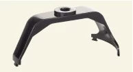
|
Used for removing / installing the fuel pump plate cover
|
|
Cover the connection with a clean cloth since the residual fuel may be released after "Release
Residual
Pressure in Fuel Line" procedures.
|
| 1.
|
Release the residual pressure in fuel line.
(Refer to Fuel Delivery System - "Release Residual Pressure in
Fuel
Line")
|
| 2.
|
Disconnect the battery negative ( - ) terminal.
|
| 3.
|
Remove the rear seat assembly.
(Refer to Body - "Rear Seat Assembly")
|
| 4.
|
Remove the fuel pump service cover (A).
|
| 5.
|
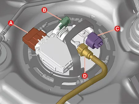
Disconnect the connectors.
A : Fuel Pump Control Module (FPCM)
B : Fuel Pressure Sensor (FPS)
C : Fuel Tank Pressure Sensor (FTPS)
D : Fuel Feed Tube
|
| 6.
|
Remove the plate cover (A) by using the SST (09310 - B8100).
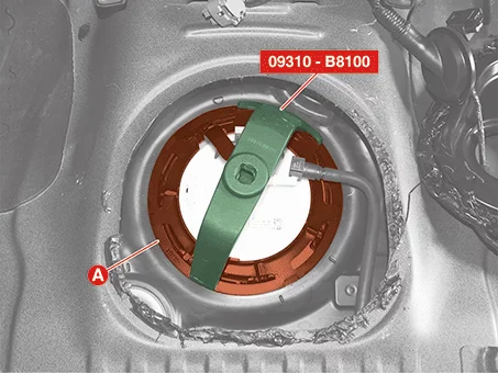

Proper Use of SST and Safe Working Posture for Removing the Tightly Fastened Plate Cover (Play
▶)
Video: Proper Use of SST and
Safe Working
Posture for Removing the Tightly Fastened Plate Cover
Notes When Refering Video
This video helps recognize potential hazards in advance and ensures procedures are performed
correctly
when safety precautions are required or when failure to follow steps or procedural errors could
affect
driving safety.
|
•
|
This video is created using common specifications and may differ from the
actual vehicle.
|
|
•
|
The location and repair procedures of the parts may vary depending on vehicle
model, model year,
region, and specifications.
|
|
•
|
Check the KDS Guide for detailed information on how to use the KDS.
|
|
•
|
Check the manual for detailed maintenance procedures.
|
|
•
|
Unauthorized reproduction, distribution, or sharing of this video is
prohibited.
|
|
| 7.
|
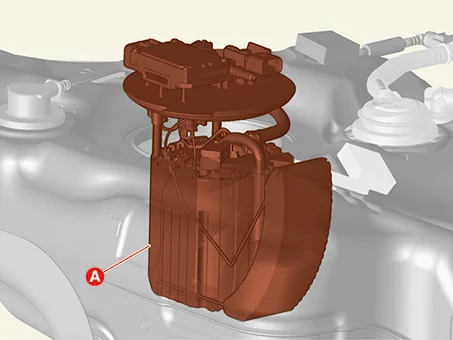
Remove the fuel pump module (A) from the fuel tank.
|
| 1.
|
Install in the reverse order of removal.
|
•
|
Be careful not to get foreign matter into the fuel tank.
|
|
•
|
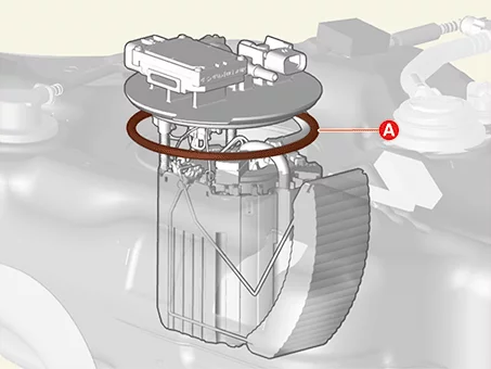
Be careful not to miss O-ring (A).
|
|
|
| 2.
|
Check for fuel leaks after installation.
|
Fuel Sender Specification
Floating Position
|
Resistance (Ω)
|
Capacity
[ℓ (U.S gal.,
U.S.qt.,
Imp.qt.)]
|
Full
|
14 - 16
|
46.1 (12.18, 48.71, 40.56)
|
1/2
|
77.4 - 81.4
|
25 (6.60, 26.42, 22.00)
|
Empty
|
297 - 305
|
2 (0.53, 2.11, 1.76)
|
Fuel Sender Components and Components Location
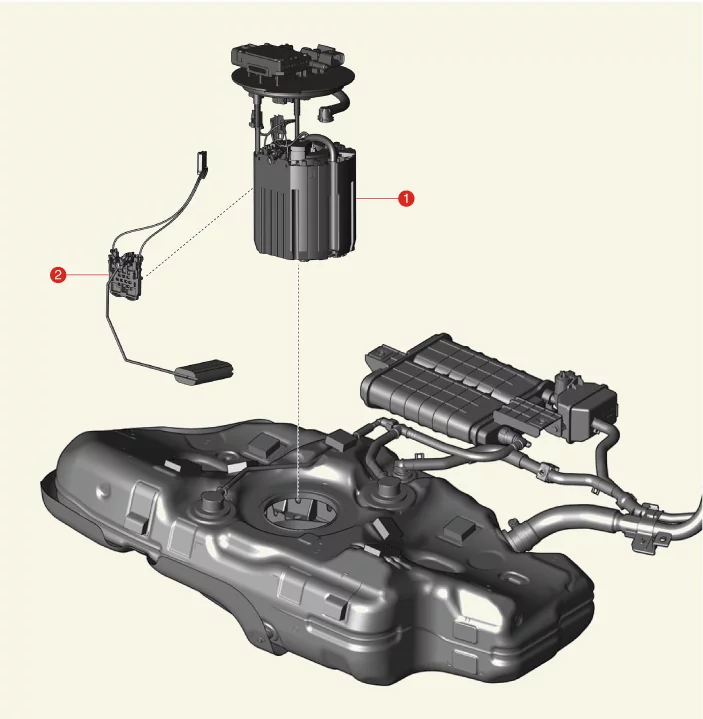
1. Fuel Pump Module
|
2. Fuel Sender
|
Fuel Sender On Vehicle Inspection
| 1.
|
Remove the rear seat cushion.
(Refer to Body - "Rear Seat Assembly")
|
| 2.
|
Disconnect the fuel pump module connector.
|
| 3.
|
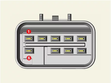
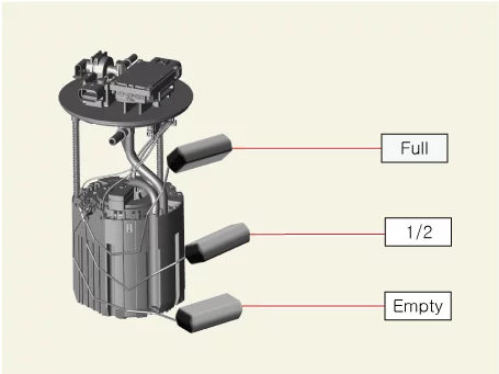
Put the float of the fuel sender at the top and bottom positions and measure the resistance
between
terminals 3 ( + ) and 1 ( - ) of the fuel pump connector.
|
| 4.
|
Check that the resistance is within the specification.
Floating Position
|
Resistance (Ω)
|
Capacity
[ℓ
(U.S gal.,
U.S.qt., Imp.qt.)]
|
Full
|
14 - 16
|
46.1 (12.18, 48.71, 40.56)
|
1/2
|
77.4 - 81.4
|
25 (6.60, 26.42, 22.00)
|
Empty
|
297 - 305
|
2 (0.53, 2.11, 1.76)
|
|
Fuel Sender Removal and Installation
| 1.
|
Remove the fuel pump module.
(Refer to Fuel Delivery System - "Fuel Pump Module")
|
| 2.
|
Disconnect the fuel sender connector (A).
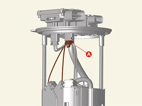
|
| 3.
|
Remove the fuel sender assembly (A) after releasing the fixing clip by pressing it in the
direction of
the arrow.
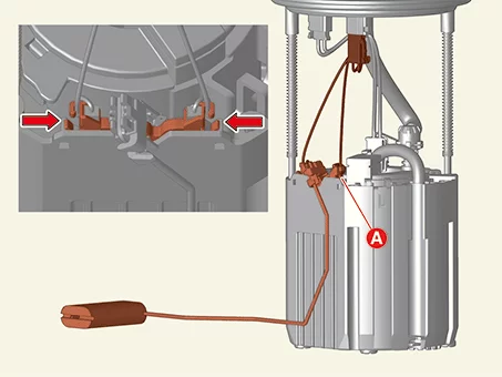
|
| 1.
|
Install in the reverse order of removal.
|
| 2.
|
Check for fuel leaks after installation.
|
Fuel Tank Specification
Item
|
Specification
|
Capacity [ℓ (U.S gal., U.S.qt., Imp.qt.)]
|
47 (12.42, 49.66, 41.35)
|
Fuel Tank Components and Components Location
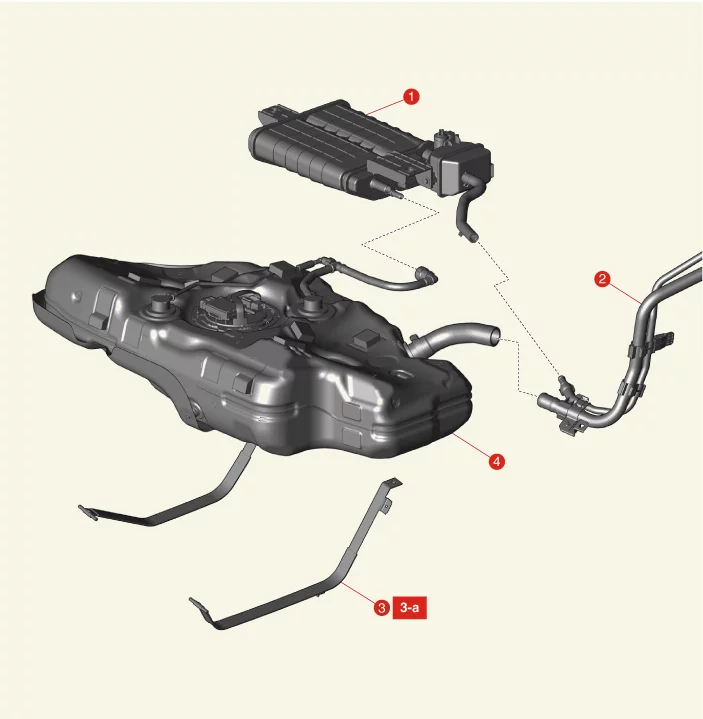
1. Canister
2. Filler-Neck Assembly
|
3. Fuel Tank Band
3-a. 39.2 - 53.9 N·m (4.0
- 5.5
kgf·m, 28.9 - 39.8 lb·ft)
4. Fuel Tank
|
Fuel Tank Removal and Installation
| 1.
|
Remove the fuel pump module.
(Refer to Fuel Delivery System - "Fuel Pump Module")
|
| 2.
|
Remove the fuel filler hose (A) after releasing the clamp bolt.
|
Tightening torque :
4.2 - 4.8 N·m (0.43 - 0.49 kgf·m, 3.1 - 3.5 lb·ft, 37.3 - 42.5 lb·in)
|
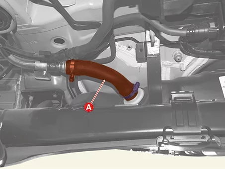
|
| 3.
|
Disconnect the fuel tank vapor hose (A).
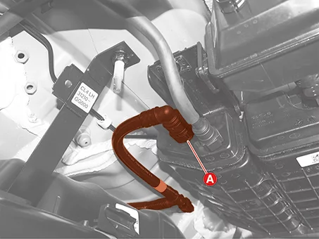
|
| 4.
|
Support the fuel tank by jack (A).
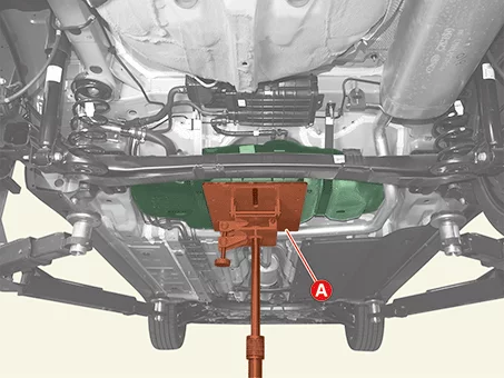
|
| 5.
|
Remove the fuel tank bands (A) after removing the nuts.
|
Tightening torque :
39.2 - 53.9 N·m (4.0 - 5.5 kgf·m, 28.9 - 39.8 lb·ft)
|
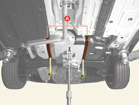
|
| 6.
|
Remove the fuel tank (A) by slowly down the jack.
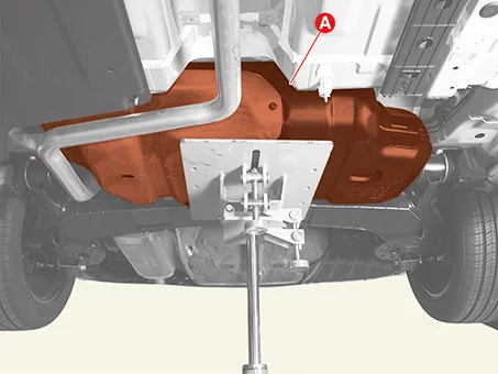
|
| 1.
|
Install in the reverse order of removal.
|
•
|
Install the fuel tank to the specified torque.
|
|
•
|
Be careful not to drop the fuel tank when installing the fuel
tank.
|
|
|
| 2.
|
Check for fuel leaks after installation.
|
High Pressure Fuel Pump Specifications
Item
|
Specification
|
System pressure [MPa (kg/cm², psi)]
|
2 - 35 (20.4 - 356.9, 290.1 - 5076.3)
|
Pump speed (rpm)
|
Maximum 3,500
|
Coil resistance (Ω)
|
0.52 - 0.58 (Room temperature)
|
High Pressure Fuel Pump Components and Components Location
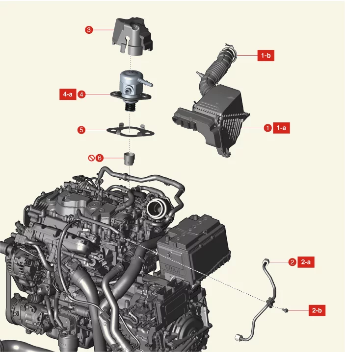
1. Air Cleaner Assembly
1-a. 7.8 - 9.8 N·m
(0.8 -
1.0 kgf·m, 5.8 - 7.2 lb·ft)
1-b. 2.9 - 4.9 N·m (0.3 - 0.5 kgf·m, 2.2 - 3.6 lb·ft, 26.0 - 43.4
lb·in)
2.
High Pressure Fuel Pump Foam
|
3. High Pressure Fuel Pipe
3-a. 32.4 - 35.3
N·m
(3.3 - 3.6 kgf·m, 23.9 - 26.0 lb·ft)
3-b. 9.8 - 11.8 N·m (1.0 - 1.2 kgf·m, 7.2 - 8.7 lb·ft)
|
High Pressure Fuel Pump On Vehicle Inspection
| 1.
|
The fuel delivery system can be more quickly diagnosed for problems with the KDS. (Refer to
"DTC guide")
| (1)
|
Self Diagnosis : Inspect the Diagnostic Trouble Code (DTC) with the KDS
(Refer to DTC guide when fault code is found)
|
| (2)
|
Data Analysis : Checking the system input/output data state
(Data Analysis → System Selection → Engine)
(Measure → Oscilloscope)
|
|
Refer to the KDS screen for operating conditions and details
|
|
| 1.
|
Separate the breather hose (A) after releasing the clamp.
|
| 2.
|
Remove the high pressure fuel pump foam (A).
|
| 3.
|
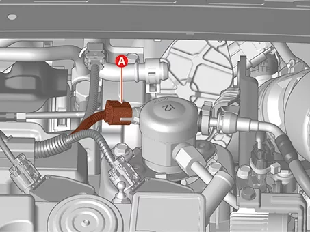
Disconnect the high pressure fuel pump connector (A).
|
| 4.
|
Measure resistance between the high pressure fuel pump terminals 1 and 2.
|
| 5.
|
Check that the resistance is within the specification.
Item
|
Specification
|
Coil resistance (Ω)
|
0.52 - 0.58 (Room temperature)
|
|
High Pressure Fuel Pump Removal and Installation
|
Since there is a risk of injury due to high pressure fuel leakage, do not perform any work
right after
the engine is stopped.
|
|
Cover the connection with a clean cloth since the residual fuel may be released after "Release
Residual
Pressure in Fuel Line" procedures.
|
| 1.
|
Release the residual pressure in fuel line.
(Refer to Fuel Delivery System - "Release Residual Pressure in
Fuel
Line")
|
| 2.
|
Disconnect the battery negative ( - ) terminal.
|
| 3.
|
Remove the high pressure fuel pipe.
(Refer to Fuel Delivery System - "Fuel Line")
|
| 4.
|
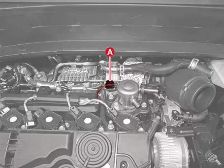
Disconnect the high pressure fuel pump connector (A).
|
| 5.
|
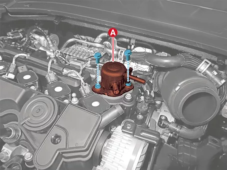
Remove the high pressure fuel pump (A) after removing the bolts.
|
Tightening torque :
12.7 - 14.7 N·m (1.3 - 1.5 kgf·m, 9.4 - 10.8 lb·ft)
|
|
Remove the bolts alternately. If (only) one of bolts is completely removed, the
housing surface
of the cylinder head may be damaged due to the spring tension of the
high-pressure fuel pump.
|
|
| 6.
|
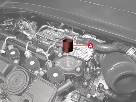
Remove the roller tappet (A).
|
| 1.
|
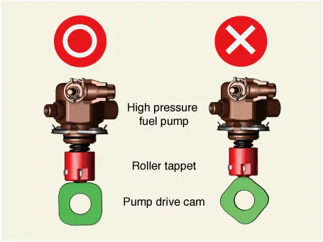
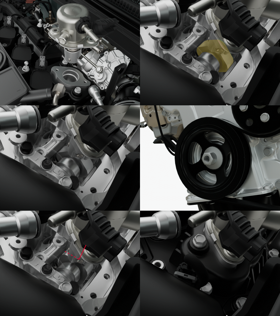
After checking the pump drive cam position, place the cam position to BDC by turning the damper
pulley in
the direction of clockwise.
If the high pressure fuel pump is installed in a position other than the BDC,
the following
problems may occur.
|
•
|
O-rings may be damaged due to incomplete tightening.
|
|
•
|
High pressure fuel pump piston tightening bolt thread may be
damaged.
|
|
|
| 2.
|
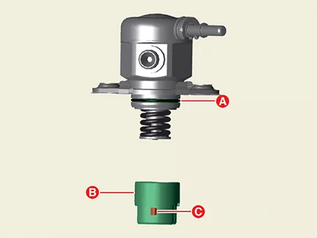
Apply engine oil to the O-ring (A), roller tappet (B), guide pin (C) and mounting groove of the
high
pressure fuel pump.
|
Replace the O-ring and gasket with a new one. (Do not reuse)
|
|
| 3.
|
After installing the high pressure fuel pump (A) and the roller tappet, pre-tighten the bolt by
hand.
|
•
|
Tighten the bolts by a half turn alternately. If (only) one of
the bolts is completely
tightened, the housing surface of cylinder head may be damaged
due to the spring tension of
the high-pressure fuel pump.
|
|
•
|
Do not reuse the bolts.
|
|
|
| 4.
|
Tighten the high pressure fuel pump bolts to the specified torque.
|
Tightening torque :
12.7 - 14.7 N·m (1.3 - 1.5 kgf·m, 9.4 - 10.8 lb·ft)
|
|
| 5.
|
Install in the reverse order of removal.
|
Replace the high pressure fuel pipe with a new one. (Do not reuse)
|
|
| 6.
|
Check for fuel leaks after installation.
|
Injector Components and Components Location
1. Air Cleaner Assembly
1-a. 7.8 - 9.8 N·m
(0.8 -
1.0 kgf·m, 5.8 - 7.2 lb·ft)
1-b. 2.9 - 4.9 N·m (0.3 - 0.5 kgf·m, 2.2 - 3.6 lb·ft, 26.0 - 43.4
lb·in)
2.
High Pressure Fuel Pump Foam
3. Intake Manifold
3-a. 18.6 - 23.5 N·m (1.9 - 2.4 kgf·m, 13.7 -
17.4
lb·ft)
4. Injector Foam
5. Delivery Pipe & Injector Wiring
|
6. High Pressure Fuel Pipe
6-a. 32.4 - 35.3
N·m
(3.3 - 3.6 kgf·m, 23.9 - 26.0 lb·ft)
6-b. 9.8 - 11.8 N·m (1.0 - 1.2 kgf·m, 7.2 - 8.7 lb·ft)
7.
Delivery
Pipe
7-a. 24.5 - 27.5 N·m (2.5 - 2.8 kgf·m, 18.1 - 20.3 lb·ft)
8. Clip
9. Injector
10.
Rail
Pressure Sensor (RPS)
10-a. 30.4 - 34.3 N·m (3.1 - 3.5 kgf·m, 22.4 - 25.3 lb·ft)
|
1. Wiring
2. Rail Pressure Sensor
(RPS)
2-a.
30.4 - 34.3 N·m (3.1 - 3.5 kgf·m, 22.4 - 25.3 lb·ft)
|
3. Injector
4. Delivery Pipe
|
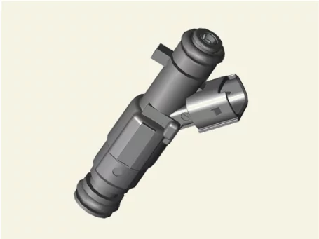
Injector Description and Operation
|
•
|
Injector is an electronically controlled fuel injection device that is a solenoid valve that
supplies
accurately calculated fuel to the engine in the form of spray for optimal combustion for various
engine
operating conditions.
|
|
•
|
Engine Control Module (ECM) controls the amount of fuel injection to meet the air-fuel ratio
(AFR)
required by the engine control system by measuring the air-fuel ratio of intake air volume and
exhaust gas
and adjusting the injector operating time to improve fuel efficiency, engine performance and
reduce the
exhaust gas.
|
Injector On Vehicle Inspection
| 1.
|
The fuel delivery system can be more quickly diagnosed for problems with the KDS. (Refer to
"DTC guide")
| (1)
|
Self diagnosis : Inspect the Diagnostic Trouble Code (DTC) with the KDS
(Refer to DTC guide when fault code is found)
|
| (2)
|
Data analysis : Checking the system input/output data state
(Data Analysis → System Selection → Engine)
|
| (3)
|
Actuation test : Checking the system operation condition
(Data Analysis → System Selection → Engine → Actuation test → Injector
Disable-Cylinder 1 / 2 / 3
/ 4)
|
|
Refer to the KDS screen for operating conditions and details
|
|
| 2.
|
Disconnect the injector connectors.
|
| 3.
|
Measure the resistance between the injector terminals.
|
| 4.
|
Check that the resistance is within the specification.
Item
|
Specification
|
Coil resistance (Ω)
|
14.5
|
|
Injector Removal and Installation
|
•
|
This video was created using 3D graphics to help understand the vehicle
maintenance manual.
|
|
•
|
There may be some differences from actual vehicles.
|
|
•
|
The location and repair procedures of the parts may vary depending on vehicle
model, model year,
region, and specifications.
|
|
•
|
Check the KDS Guide for detailed information on how to use the KDS.
|
|
•
|
Check the manual for detailed maintenance procedures.
|
|
•
|
Unauthorized reproduction, distribution, or sharing of this video is
prohibited.
|
|
Injector Removal
(Click to play)
Video: Injector Removal
| 1.
|
Remove the injector from the delivery pipe.
(Refer to Fuel Delivery System - "Delivery Pipe")
|
| 1.
|
Install in the reverse order of removal.
|
•
|
Install the delivery pipe to the specified torque.
|
|
•
|
If the injector is dropped, it may cause internal damage. (Do
not reuse)
|
|
•
|
Be careful not to get foreign matter into the injector hole.
|
|
•
|
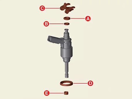
Replace the parts below with a new one.
A : O-ring
B : Support disc
C : Clip
D : Rubber washer
(When installing the rubber washer, make sure that the steel
plate side faces the
mounting area of the cylinder and the rubber plate side faces
the injector body.)
E : Combustion seal ring
(Refer to Injector -
"Replacement")
|
|
•
|
Apply engine oil to the O-rings.
|
|
•
|
Do not apply engine oil to the combustion seal ring.
|
|
|
Injector Replacement
|
•
|
This video was created using 3D graphics to help understand the vehicle
maintenance manual.
|
|
•
|
There may be some differences from actual vehicles.
|
|
•
|
The location and repair procedures of the parts may vary depending on vehicle
model, model year,
region, and specifications.
|
|
•
|
Check the KDS Guide for detailed information on how to use the KDS.
|
|
•
|
Check the manual for detailed maintenance procedures.
|
|
•
|
Unauthorized reproduction, distribution, or sharing of this video is
prohibited.
|
|
Injector Seal Ring Replacement
(Click to play)
Video: Injector Seal Ring Replacement
Tool Name / Number
|
Illustration
|
Description
|
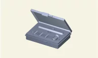
Injector combustion seal ring guide & sizing tool
09353 - L1100
|
|
Used for installing injector combustion seal ring on injector
|
|
The combustion seal ring must be replaced with the following procedure to prevent oil leak or
leakage.
|
| 1.
|
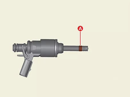
Remove the combustion seal ring (A).
|
Be careful not to damage the injector when removing the combustion seal ring.
|
|
| 2.
|
Brush off the dirt on the surface of the injector with the combustion seal ring off, then wipe
off.
|
| 3.
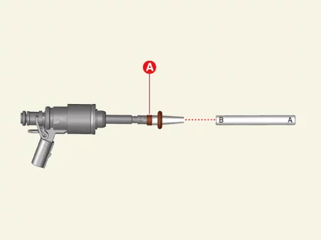
|
Install the combustion seal ring by using SST (09353 - L1100).
| (1)
|
Install the mounting guide (A) from the injector.
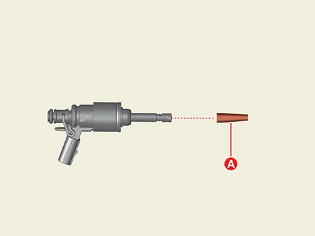
|
| (2)
|
Install the combustion seal ring (A) from the mounting guide.
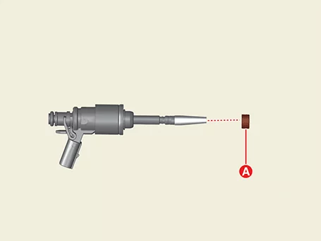
|
| (3)
|
Install the rubber ring (A) from the mounting guide.
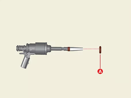
|
| (4)
|
After pushing the seal ring (A) in the "A" direction of the installer, push the
seal ring (A) in
the "B" direction of the installer to the mounting area of the Combustion seal
ring.
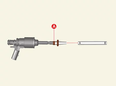
|
Install it by pushing it in within 2-3 seconds in order not to
increase the size.
|
|
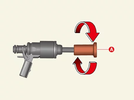
| (5)
|
Install the presser (A), rotate it 3 to 4 times from side to side and remove
it.
|
| (6)
|
Check the seal ring (A) installation.
|
|
Rail Pressure Sensor (RPS) Specifications
Item
|
Specification
|
Rated voltage (V)
|
5
|
Operating voltage (V)
|
4.75 - 5.25
|
Operating temperature [°C (°F)]
|
-40 to 140 (-40 to 284)
|
Operating pressure [bar (MPa, kg/cm², psi)]
|
0 - 450 (0 - 45, 0 - 458.9, 0 - 6526.7)
|
Pressure Characteristics
Item
|
Specification
|
Pressure
|
bar
|
0
|
225
|
450
|
kg/cm²
|
0
|
229.4
|
458.9
|
psi
|
0
|
3263.3
|
6526.7
|
Output voltage [(V), 25°C (77°F)]
|
0.46 - 0.54
|
2.444 - 2.556
|
4.428 - 4.572
|
Rail Pressure Sensor (RPS) Components and Components Location
1. Air Cleaner Assembly
1-a. 7.8 - 9.8 N·m
(0.8 -
1.0 kgf·m, 5.8 - 7.2 lb·ft)
1-b. 2.9 - 4.9 N·m (0.3 - 0.5 kgf·m, 2.2 - 3.6 lb·ft, 26.0 - 43.4
lb·in)
2.
High Pressure Fuel Pump Foam
3. Intake Manifold
3-a. 18.6 - 23.5 N·m (1.9 - 2.4 kgf·m, 13.7 -
17.4
lb·ft)
4. Injector Foam
5. Delivery Pipe & Injector Wiring
|
6. High Pressure Fuel Pipe
6-a. 32.4 - 35.3
N·m
(3.3 - 3.6 kgf·m, 23.9 - 26.0 lb·ft)
6-b. 9.8 - 11.8 N·m (1.0 - 1.2 kgf·m, 7.2 - 8.7 lb·ft)
7.
Delivery
Pipe
7-a. 24.5 - 27.5 N·m (2.5 - 2.8 kgf·m, 18.1 - 20.3 lb·ft)
8. Clip
9. Injector
10.
Rail
Pressure Sensor (RPS)
10-a. 30.4 - 34.3 N·m (3.1 - 3.5 kgf·m, 22.4 - 25.3 lb·ft)
|
Rail Pressure Sensor (RPS) Description and Operation
|
•
|
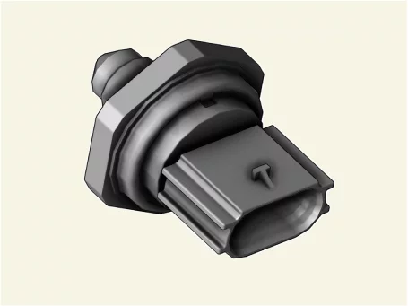
The Rail Pressure Sensor (RPS) is to measure the fuel pressure in the delivery pipe and
transmits the
voltage value to Engine Control Module (ECM).
|
|
•
|
The ECM uses the voltage signal to control the exact amount of fuel injection, spraying period
and if the
target fuel pressure differs from the actual fuel pressure, ECM uses the fuel pressure control
valve to
control the fuel pressure.
|
Rail Pressure Sensor (RPS) On Vehicle Inspection
| 1.
|
The fuel delivery system can be more quickly diagnosed for problems with the KDS. (Refer to
"DTC guide")
| (1)
|
Self Diagnosis : Inspect the Diagnostic Trouble Code (DTC) with the KDS
(Refer to DTC guide when fault code is found)
|
| (2)
|
Data Analysis : Checking the system input/output data state
(Data Analysis → System Selection → Engine)
(Measure → Oscilloscope)
Item
|
Specification
|
Pressure
|
bar
|
0
|
225
|
450
|
kg/cm²
|
0
|
229.4
|
458.9
|
psi
|
0
|
3263.3
|
6526.7
|
Output voltage [(V), 25°C (77°F)]
|
0.46 - 0.54
|
2.444 - 2.556
|
4.428 - 4.572
|
|
|
Refer to the KDS screen for operating conditions and details
|
|
Rail Pressure Sensor (RPS) Removal and Installation
|
Since there is a risk of injury due to high pressure fuel leakage, do not perform any work
right after
the engine is stopped.
|
| 1.
|
Release the residual pressure in fuel line.
(Refer to Fuel Delivery System - "Release Residual Pressure in
Fuel
Line")
|
| 2.
|
Remove the intake manifold.
(Refer to Engine Mechanical System - "Intake Manifold")
|
| 3.
|
Remove the injector foam (A).
|
| 4.
|
Disconnect the Rail Pressure Sensor (RPS) connector (A).
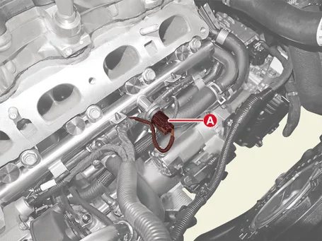
|
| 5.
|
Remove the RPS (A).
|
Tightening torque :
30.4 - 34.3 N·m (3.1 - 3.5 kgf·m, 22.4 - 25.3 lb·ft)
|
|
| 1.
|
Install in the reverse order of removal.
|
•
|
Install the Rail Pressure Sensor (RPS) to the specified torque.
|
|
•
|
If the RPS is dropped, it may cause internal damage. (Do not
reuse)
|
|
|
| 2.
|
Reset the Engine Control Module (ECM) adaptive values with the KDS.
(S/W Management → Engine Control → Resetting Adaptive Values)
|
Refer to the KDS screen for operating conditions and details
|
|
Other information:
Kia K4 (CL4) 2025-2026 Service Manual: Seat belt restraint system
To ensure maximum protection, occupants must wear their seat belts whenever the Kia K4 is in motion:
The shoulder belt should be adjusted to rest midway over the shoulder and across the collarbone, never against the neck.
For safety reasons, never allow children to ride in the front passenger seat. Please refer to the "Child Restraint System (CRS)" section of your Kia K4 owner's manual for detailed guidance on appropriate child seating.
Kia K4 (CL4) 2025-2026 Service Manual: Description and Operation
Description
Advanced Driver Assistance System (ADAS) analyzes the exterior environment of the vehicle and driver status to
provide visibility / display / guide / warning for driving and parking.
Function
Controller
Abbreviation
Name
Front View Camera
Front



 : Pre-tighten the flange nuts by hand
 : Tighten the high pressure fuel pipe
holder bolt
9.8 - 11.8 N·m (1.0 - 1.2 kgf·m, 7.2 - 8.7
lb·ft)
 : Tighten the flange nuts to
specified torque
32.4 - 35.3 N·m (3.3 - 3.6 kgf·m, 23.9 - 26.0
lb·ft)