Contents:
Components and Components Location
|
•
|
This video was created using 3D graphics to help understand the vehicle
maintenance manual.
|
|
•
|
There may be some differences from actual vehicles.
|
|
•
|
The location and repair procedures of the parts may vary depending on vehicle
model, model year,
region, and specifications.
|
|
•
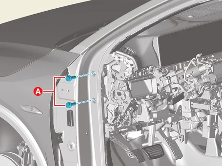
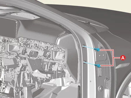
|
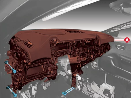
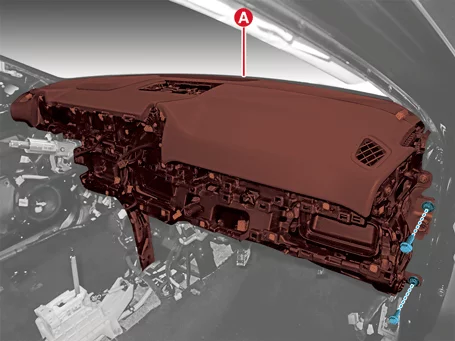
Check the KDS Guide for detailed information on how to use the KDS.
|
|
•
|
Check the manual for detailed maintenance procedures.
|
|
•
|
Unauthorized reproduction, distribution, or sharing of this video is
prohibited.
|
|
Heater Components
(Click to play)

Video: Heater Components
1. Blower Unit
|
8. Temperature Control Actuator [Driver’s
side]
|
2. Temperature Control Actuator [Passenger’s
side]
|
9. Heater Core Cover
|
3. Auto Defogingg Actuator
|
10. Heater Core
|
4. Shower Duct [Passenger’s side]
|
11. Shower Duct [Driver’s side]
|
5. Heater Unit Lower Case
|
12. PTC Heater
|
6. Evaporator Core
|
13. In-car Sensor Hose
|
7. Mode Control Actuator
|
On Vehicle Inspection
| 1.
|
The heater system can be more quickly diagnosed for problems with the KDS (Refer to "DTC
guide").
| (1)
|
Self diagnosis : Inspect the Diagnostic Trouble Code (DTC) with the KDS.
(Refer to DTC guide when fault code is found)
|
|
Refer to the KDS screen for operating conditions and details.
|
|
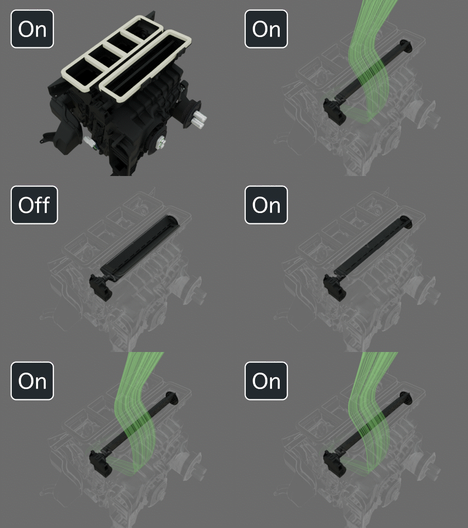
Auto Defogging Actuator Description and Operation
That detects fogging with a auto defogging sensor and automatically operates the air conditioning system to
prevent fogging.
Auto Defogging Actuator Removal and Installation
Auto Defogging Actuator
| 1.
|
Remove the crash pad assembly.
(Refer to Body - "Crash Pad Assembly")
|
| 2.
|
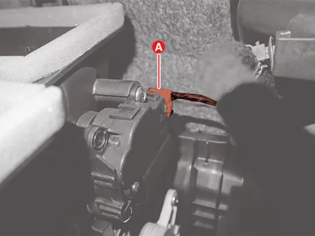
Disconnect the actuator connector (A).
|
| 3.
|
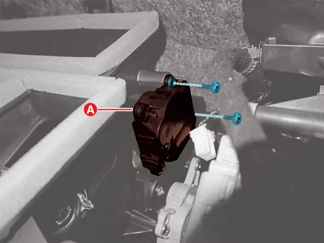
Remove the actuator (A) after removing the screws.
|
| 1.
|
Install in the reverse order of removal.
|
Auto Defogging Actuator Inspection
| 1.
|
Disconnect the auto defogging actuator connector.
(Refer to Heater - "Auto Defogging Actuator")
|
| 2.
|
Apply voltage to the temperature control actuator 3 terminal and ground the 7 terminal to check
whether
the actuator operates.
|
| 3.
|
When connecting in the opposite, check if it operates in reverse.
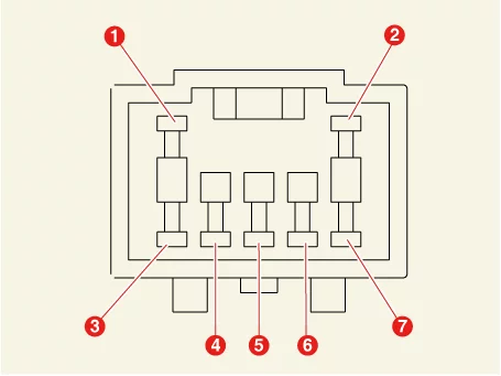
1. -
2. -
3. DEF
(Open)
4. Sensor
Power (5 V)
|
5. Feedback Signal
6.
Sensor Ground
7.
Closed
|
|
| 4.
|
Connect the auto defogging actuator connector.
|
| 6.
|
Measure the terminal voltage between 5 and 6.
Door Position
|
Voltage (V)
|
Error Detection
|
DEF closed
|
0.35 - 0.65
|
Low voltage : below 0.1 V
|
DEF open
|
4.35 - 4.65
|
High voltage : above 4.9 V
|
* Feedback the current position of the actuator to the control.
|
| 7.
|
If the measured voltage does not match the specifications, replace it with a new auto defogging
actuator.
|
Auto Defogging Sensor Removal and Installation
Auto Defogging Sensor
| 1.
|
Remove the multi sensor cover.
(Refer to Body - "Multi Sensor Cover")
|
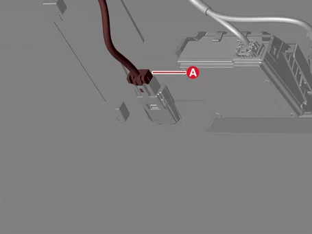
| 2.
|
Disconnect the sensor connector (A).
|
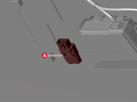
| 3.
|
Remove the sensor (A).
|
| 1.
|
Install in the reverse order of removal.
|
Duct Removal and Installation
|
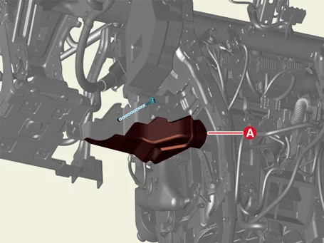
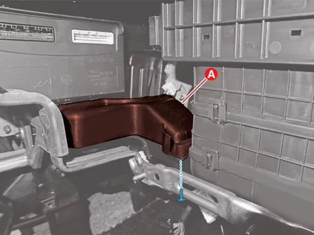
The indication below represents the location of a clip or fastener.

|
Shower Duct [Driver's Side]
| 1.
|
Remove the crash pad lower panel.
(Refer to Body - "Crash Pad Panel")
|
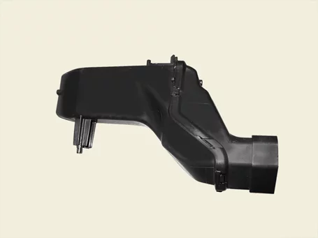
| 2.
|
Remove the duct (A) after removing the screw.
|
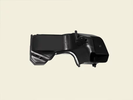
Shower Duct [Passenger's Side]
| 1.
|
Remove the crash pad center panel.
(Refer to Body - "Crash Pad Panel")
|
| 2.
|
Remove the duct (A) after removing the screw.
|
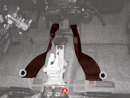
Rear Heating Duct Assembly
| 1.
|
Remove the floor carpet assembly.
(Refer to Body - "Floor Carpet Assembly")
|
| 2.
|
Remove the duct assembly (A).
|
| 1.
|
Install in the reverse order of removal.
|
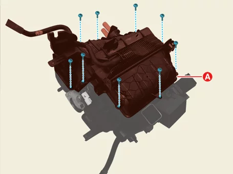
Evaporator Core Removal and Installation
| 1.
|
Remove the heater unit.
(Refer to Heater - "Heater Unit")
|
| 2.
|
Remove the evaporator core cover (A) after removing the screws.
|
| 3.
|
Remove the evaporator core (A).
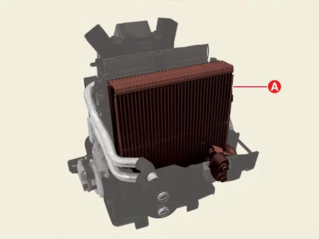
|
| 1.
|
Install in the reverse order of removal.
|
Heater Core Removal and Installation
| 1.
|
Remove the heater unit.
(Refer to Heater - "Heater Unit")
|
| 2.
|
Remove the heater core cover (A) after removing the screws.
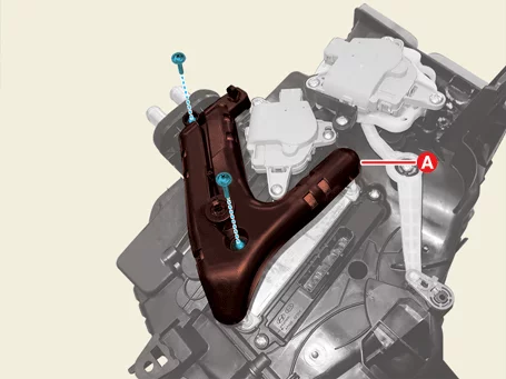
|
| 3.
|
Remove the heater core (A).
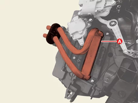
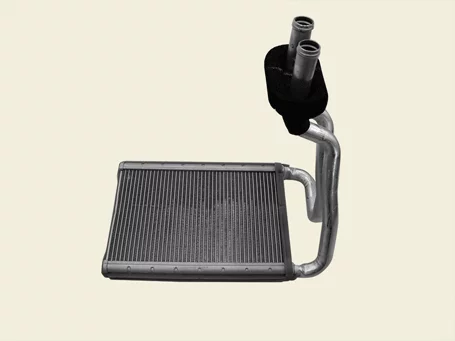
|
| 1.
|
Install in the reverse order of removal.
|
Heater Unit Removal and Installation
|
•
|
This video was created using 3D graphics to help understand the vehicle
maintenance manual.
|
|
•
|
There may be some differences from actual vehicles.
|
|
•
|
The location and repair procedures of the parts may vary depending on vehicle
model, model year,
region, and specifications.
|
|
•
|
Check the KDS Guide for detailed information on how to use the KDS.
|
|
•
|
Check the manual for detailed maintenance procedures.
|
|
•
|
Unauthorized reproduction, distribution, or sharing of this video is
prohibited.
|
|
Heater Unit Removal
(Click to play)
Video: Heater Unit Removal
|
The indication below represents the location of a clip or fastener.
|
| 1.
|
Recover the refrigerant by using recovery/recycling/charging equipment.
(Refer to Air Conditioning System - "Refrigerant
Recovery/Recycling/Charging/Vacuum/Leak Test")
|
| 2.
|
Drain the coolant.
(Refer to Engine Mechanical System - "Coolant")
|
| 3.
|
Remove the front wiper motor.
(Body - "Wiper Motor")
|
| 4.
|
Remove the front pillar trim.
(Refer to Body - "Front Pillar Trim")
|
| 5.
|
Remove the crash pad center panel.
(Refer to Body - "Crash Pad Panel")
|
| 6.
|
Remove the powernet domain controller.
(Refer to Body - "Junction Block")
|
| 7.
|
Lower the steering column after removing the nuts and through-bolt.
(Refer to Steering System - "Steering Column Assembly")
|
| 8.
|
Remove the rear heating duct assembly.
(Refer to Heater - "Duct")
|
| 9.
|
Disconnect the heater hoses (A) after releasing the clamps.
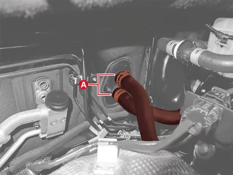
|
| 10.
|
Disconnect the main wiring harness connectors.
| (1)
|
Disconnect the MDPS connectors (A, B).
A : MDPS power connector
B : MDPS signal connector
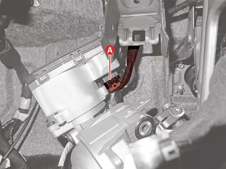
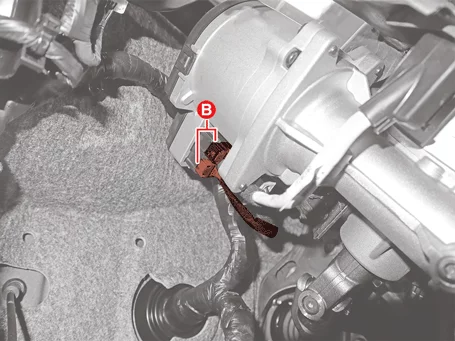
|
| (2)
|
Disconnect the brake switch connector (A).
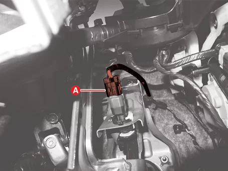
|
|
| 11.
|
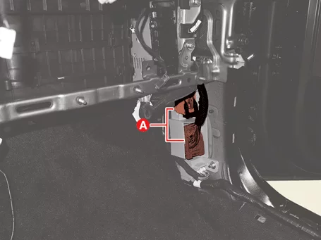
Disconnect the multi-box connectors (A).
Driver's Side
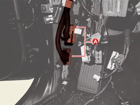
Passenger's Side
|
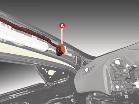
| 12.
|
Disconnect the roof trim connector (A).
|
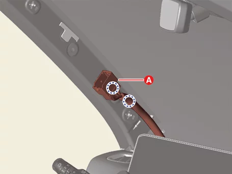
| 13.
|
Separate the roof trim wiring (A).
|
| 14.
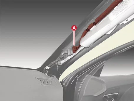
|
Disconnect the roof antenna connector (A).
|
| 15.
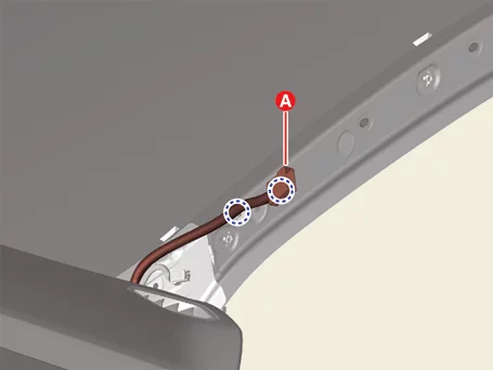
|
Separate the roof antenna wiring (A).
|
| 16.
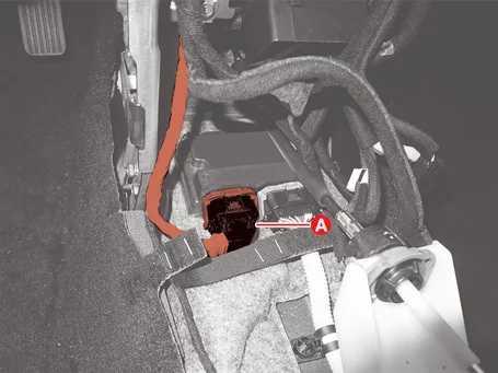
|
Disconnect the Airbag Control Unit (ACU) connector (A).
|
| 17.
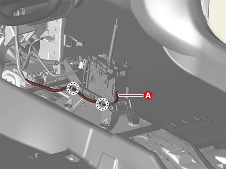
|
Disconnect the shift lever connector (A).
|
| 18.
|
Separate the drain hose (A).
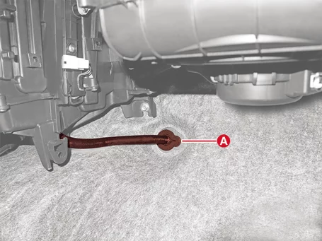
|
| 19.
|
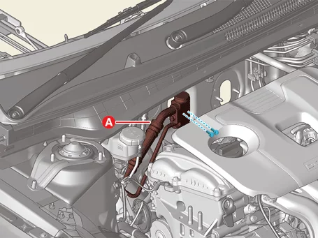
Separate the expansion valve (A) after removing the bolts.
|
Tightening torque:
8.8 - 13.7 N·m (0.9 - 1.4 kgf·m, 6.5 - 10.1 lb·ft)
|
|
| 20.
|
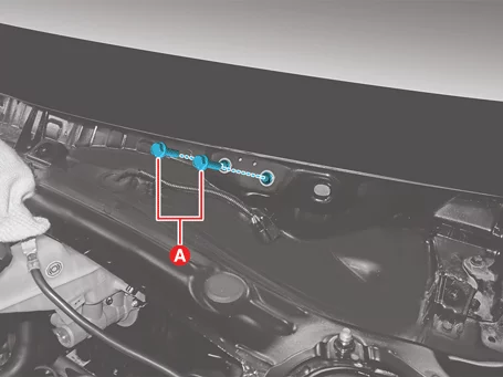
Remove the dash panel cowl cross bar through-bolts (A).
|
Tightening torque:
16.7 - 25.5 N·m (1.7 - 2.6 kgf·m, 12.3 - 18.8 lb·ft)
|
|
| 21.
|
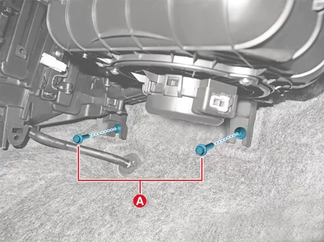
Remove the heater and blower unit lower bolt (A).
|
Tightening torque:
3.9 - 5.9 N·m (0.4 - 0.6 kgf·m, 2.9 - 4.3 lb·ft, 34.7 - 52.1 lb·in)
|
|
| 22.
|
Remove the side panel cowl cross bar through-bolts (A).
|
Tightening torque:
16.7 - 25.5 N·m (1.7 - 2.6 kgf·m, 12.3 - 18.8 lb·ft)
|
Driver's Side
Passenger's Side
|
| 23.
|
Remove the crash pad, heater and blower unit (A) after removing the bolts.
|
Tightening torque:
16.7 - 25.5 N·m (1.7 - 2.6 kgf·m, 12.3 - 18.8 lb·ft)
|
Driver's Side
Passenger's Side
|
| 24.
|
Disconnect the main wiring harness connectors. [Driver's
side]
A : Temperature control actuator connector
B : Mode control actuator connector
C : PTC heater connector
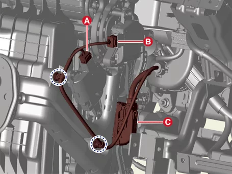
|
| 25.
|
Disconnect the main wiring harness connectors. [Passenger's
side]
| (1)
|
Disconnect the connectors (A, B, C).
A : Evaporator temperature sensor
connector
B : PWM-FET connector
C : Blower motor connector
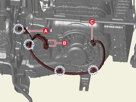
|
| (2)
|
Disconnect the connectors (A, B).
A : Temperature control actuator
connector
B : Intake actuator connector
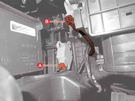
|
| (3)
|
Disconnect the auto defogging actuator connector (A).
|
|
| 26.
|
Separate the in-car sensor hose (A).
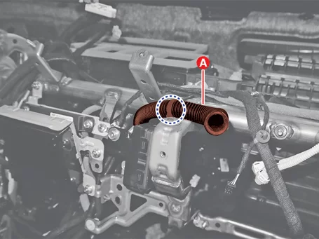
|
| 27.
|
Remove the heater and blower unit.
| (1)
|
Separate the heater and blower unit (A) after removing the bolts.
|
Tightening torque:
3.9 - 5.9 N·m (0.4 - 0.6 kgf·m, 2.9 - 4.3 lb·ft, 34.7 - 52.1
lb·in)
|
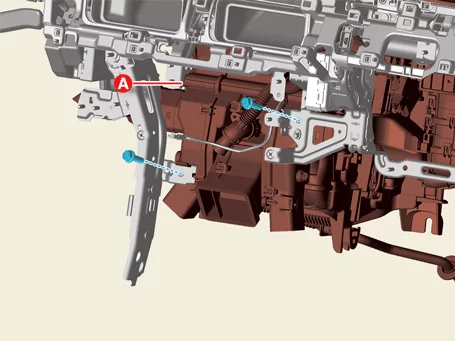
|
| (2)
|
Remove the heater and blower unit (A) after removing the nuts.
|
Tightening torque:
3.9 - 5.9 N·m (0.4 - 0.6 kgf·m, 2.9 - 4.3 lb·ft, 34.7 - 52.1
lb·in)
|
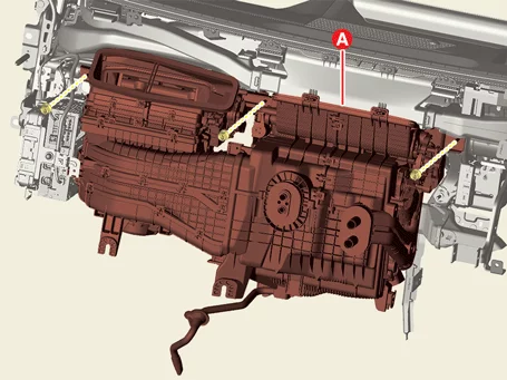
|
|
| 28.
|
Separate the heater unit (A) and the blower unit (B) after removing the screws.
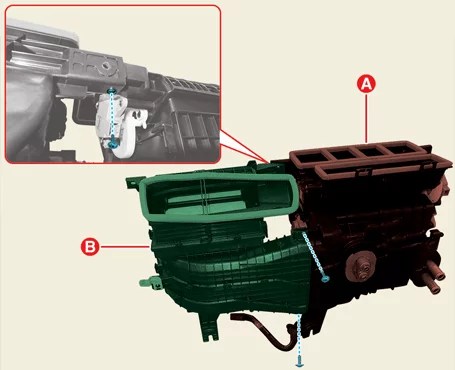
|
| 29.
|
Remove the heater drain hose (A).
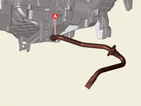
|
| 1.
|
Install in the reverse order of removal.
|
•
|
Perform the refrigerant leak test/vacuum/charging by using the
refrigerant
recovery/recycling/charging machine.
(Refer to Air Conditioning
System - "Refrigerant
Recovery/Recycling/Charging/Vacuum/Leak Test")
|
|
•
|
Perform the compressor oil inspection.
(Refer to Air Conditioning
System - "Compressor
Oil")
|
|
|
Mode Control Actuator Description and Operation
|
•
|
It is operated by a auto temperature control unit and controls the position of the mode control
door to
adjust the wind direction mode.
|
|
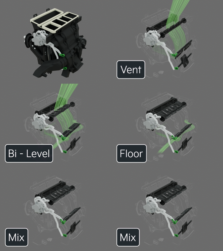
•
|
It consists of an actuator motor that moves the mode door and a potentiometer that detects the
position
of the mode door. the wind direction mode in the order of Vent → Bi-Level → Floor → Mix
|
Mode Control Actuator Removal and Installation
Mode Control Actuator
| 1.
|
Remove the crash pad assembly.
(Refer to Body - "Crash Pad Assembly")
|
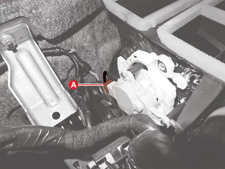
| 2.
|
Disconnect the actuator connector (A).
|
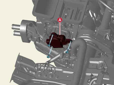
| 3.
|
Remove the actuator (A) after removing the screws.
|
| 1.
|
Install in the reverse order of removal.
|
Mode Control Actuator Inspection
| 1.
|
Disconnect the mode control actuator connector.
(Refer to Heater - "Mode Control Actuator")
|
| 2.
|
Apply voltage to the mode control actuator 3 terminal and ground the 7 terminal to check
whether the
actuator operates.
|
| 3.
|
When connecting in the opposite, check if it operates in reverse.
1. -
2. -
3. Vent
Mode
4. Sensor
Power (5 V)
|
5. Feedback Signal
6.
Sensor Ground
7.
Defrost Mode
|
|
| 4.
|
Connect the mode control actuator connector.
|
| 6.
|
Measure the voltage of the 4 - 5 terminal.
Door Position
|
Voltage (V)
|
Error Detection
|
Vent
|
0.15 - 0.45
|
Low voltage : below 0.1 V
High voltage : above 4.9 V
|
Defrost
|
4.55 - 4.85
|
* Feedback the current position of the actuator to the control.
|
| 7.
|
If the measured voltage does not match with the specifications, replace it with a new mode
control
actuator.
|
PTC Heater Description and Operation
|
•
|
The PTC (Positive Temperature Coefficient) heater is a device that is mounted on the rear side
of the
heater core and directly heats the air passing through the heater core to heat the room.
|
|
•
|
The PTC heater is an electric heating device using a PTC element as an auxiliary heating device
to
supplement the insufficient indoor heating heat source.
|
PTC Heater On Vehicle Inspection
Check The Operating Logic
| 1.
|
Set it in the floor mode and in the maximum heating position.
|
| 2.
|
Turn off the blower switch.
|
| 3.
|
Press the Recirculation mode/Fresh air mode button for at least 5 seconds.
|
| 4.
|
Recirculation and A/C indicators blink every 0.5 seconds.
|
| 5.
|
Operate the blower switch to check whether the PTC is running.
|
| 6.
|
Each PTC relay ON output operates at interval of 3 seconds.
|
| 7.
|
The operating logic will be automatically cancelled after 30 seconds, and is also cancelled in
the
followings cases:
- When selecting A/C or fresh air/recirculation switch
– IG OFF.
|
| 8.
|
If the PTC does not operate, replace with a known-good PTC heater and check whether it
operates. If the
problem is corrected, replace the PTC heater with a new one.
|
PTC Heater Removal and Installation
| 1.
|
Remove the cowl cross bar assembly.
(Refer to body - "Cowl Cross Bar Assembly")
|
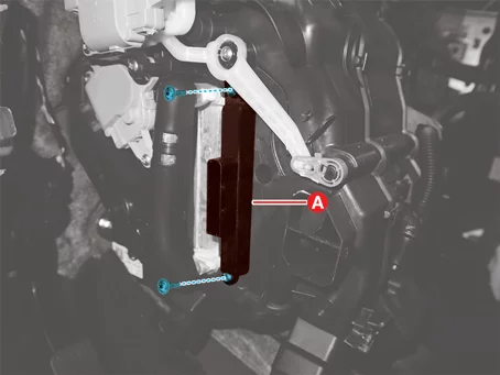
| 2.
|
Remove the PTC heater (A) after removing the screws.
|
| 1.
|
Install in the reverse order of removal.
|
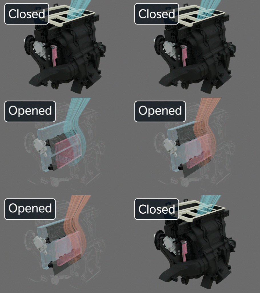
Temperature Control Actuator Description and Operation
It is operated by a auto temperature control unit and controls the position of the temperature control door to
adjust the temperature of the discharge air.
Temperature Control Actuator Removal and Installation
Temperature Control Actuator [Driver's Side]
| 1.
|
Remove the shower duct. [Driver's side]
(Refer to Heater - "Duct")
|
| 2.
|
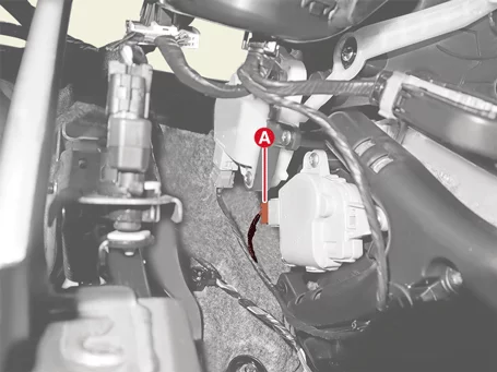
Disconnect the actuator connector (A).
|
| 3.
|
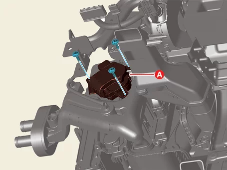
Remove the actuator (A) after removing the screws.
|
Temperature Control Actuator [Passenger's Side]
| 1.
|
Remove the shower duct. [Passenger's side]
(Refer to Heater - "Duct")
|
| 2.
|
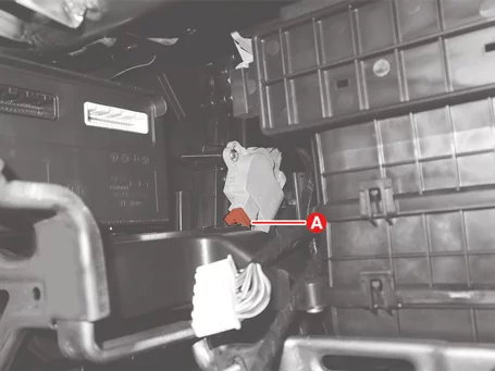
Disconnect the actuator connector (A).
|
| 3.
|
Remove the actuator (A) after removing the screws.
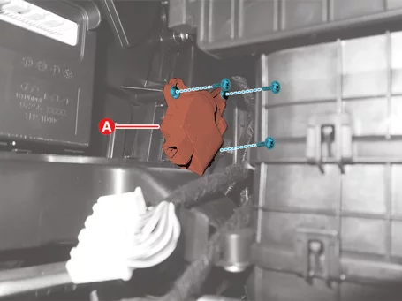
|
| 1.
|
Install in the reverse order of removal.
|
Temperature Control Actuator Inspection
Temperature Control Actuator [Driver's Side]
| 1.
|
Disconnect the temperature control actuator connector. [Driver's
side]
(Refer to Heater - "Temperature Control Actuator")
|
| 2.
|
Apply voltage to the temperature control actuator 3 terminal and ground the 7 terminal to check
whether
the actuator operates.
|
| 3.
|
When connecting in the opposite, check if it operates in reverse.
1. -
2. -
3.
Heating
4. Sensor
Ground
|
5. Feedback Signal
6.
Sensor power (5
V)
7. Cooling
|
|
| 4.
|
Connect the temperature control actuator connector.
|
| 6.
|
Check the voltage between terminal 4 and 5.
Door Position
|
Voltage (V)
|
Error Detection
|
Maximum cooling
|
0.35 - 0.65
|
Low voltage: below 0.1 V
High voltage: above 4.9 V
|
Maximum heating
|
4.35 - 4.65
|
* Feedback the current position of the actuator to the control.
|
| 7.
|
If the measured voltage does not match with the specifications, replace it with a new
temperature control
actuator.
|
Temperature Control Actuator [Passenger's Side]
| 1.
|
Disconnect the temperature control actuator connector. [Passenger's
side]
(Refer to Heater - "Temperature Control Actuator")
|
| 2.
|
Apply voltage to the temperature control actuator 3 terminal and ground the 7 terminal to check
whether
the actuator operates.
|
| 3.
|
When connecting in the opposite, check if it operates in reverse.
1. -
2. -
3.
Cooling
4. Sensor power
(5 V)
|
5. Feedback Signal
6.
Sensor Ground
7.
Heating
|
|
| 4.
|
Connect the temperature control actuator connector.
|
| 6.
|
Check the voltage between terminal 5 and 6.
Door Position
|
Voltage (V)
|
Error Detection
|
Maximum cooling
|
0.35 - 0.65
|
Low voltage: below 0.1 V
High voltage: above 4.9 V
|
Maximum heating
|
4.35 - 4.65
|
* Feedback the current position of the actuator to the control.
|
| 7.
|
If the measured voltage does not match with the specifications, replace it with a new
temperature control
actuator.
|
Other information:
Kia K4 (CL4) 2025-2026 Service Manual: Finish damage repair
If you identify chips, deep scratches, or other damage to the paint finish of your Kia K4, address these areas promptly to prevent the onset of corrosion. Small surface imperfections can often be repaired using genuine touch-up paint specifically formulated for your vehicle's color code. For larger areas of paint damage or structural bodywork issues, we recommend visiting an authorized Kia dealer to ensure the repair matches the factory standards and preserves your vehicle's long-term protection.
Kia K4 (CL4) 2025-2026 Service Manual: Windows
The doors of this premium vehicle come integrated with an advanced multi-zone power window system that allows occupants to adjust cabin airflow with tactile master armrest switches. The underlying window motors feature automated thermal protection circuitry to ensure sustained operation under heavy load variations in your Kia K4.
Power Window Lock Switch: Grants the driver the ability to completely isolate the signal path, preventing rear seat occupants from independent window operation.