Contents:
Troubleshooting
No crank
Suspected Causes
|
Correction
|
Low battery charging voltage
|
Battery charging or replace battery
|
Defective connection, corroded or worn battery terminal
|
Inspect battery terminal or replace cable
|
Broken fuse
|
Replace fuse
|
Defective starter
|
Replace starter
|
Defective body and transaxle ground cable connection condition or disconnected
|
Connect or repair ground cable
|
Defective battery positive ( + ) cable connection condition or disconnected
|
Inspect battery positive ( + ) cable connection condition and repair or replace it
|
Discharged battery
|
Replace the battery according to condition after battery charge.
|
Engine cranks slowly
Suspected Causes
|
Correction
|
Low battery charging voltage
|
Battery charging or replace battery
|
Defective connection, corroded or worn battery terminal
|
Inspect battery terminal or replace cable
|
Defective starter
|
Replace starter
|
Starter keeps running
Suspected Causes
|
Correction
|
Defective starter
|
Replace starter
|
Starter running but won't engaging
Suspected Causes
|
Correction
|
Wiring short circuit
|
Repair or replace the wiring after inspect wiring connection condition
|
Broken or worn pinion gear teeth or defective starter
|
Replace starter
|
Broken ring gear teeth
|
Replace drive plate and torque converter
|
Turn off the IG while driving
Suspected Causes
|
Correction
|
The alternator fuse wiring is disconnection so the battery is completely discharged
|
Replace alternator main fuse
|
Inspect battery condition and repair
|
Defective connection of alternator connector
|
Inspect the connector connection
|
Bad restart after the engine is turned off
Suspected Causes
|
Correction
|
Deterioration occurs due to poor positive ( + ) terminal contact
|
Replace battery wiring or Tighten at a specified torque
|
Engine cannot start even during the jump start
Suspected Causes
|
Correction
|
Excessive parasitic current occurs irregularly due to an error in smart key registration.
(Other
electronic
components and charging-related parts are normal.)
|
Reregister smart key
|
Defective wiring
|
Inspect or replace wiring
|
Discharged battery
|
Inspect or replace battery
|
On Vehicle Inspection
|
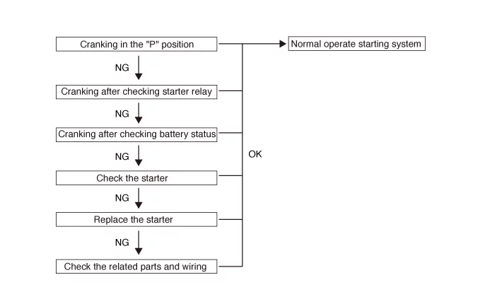
Perform the inspection procedure below.
|
| 1.
|
Check the starting system by cranking in the P position.
|
| 2.
|
Check the starting system by cranking after inspecting the starter relay.
(Refer to Starting System - "Starter Relay")
|
| 3.
|
Check the starting system by cranking after inspecting the battery condition.
(Refer to Charging System - "Battery")
Check List
|
•
|
Battery terminal connection condition
|
|
•
|
Connection condition between the battery negative ( - )
terminal and the body
|
|
|
| 4.
|
Inspect the starter.
(Refer to Starting System - "Starter")
|
| 5.
|
Inspect the starting system components and the wiring.
Check List
|
•
|
Connector and the wiring between the internal fuse box and the
start/stop button
|
|
•
|
Connector and the wiring between the internal fuse box and the
starter
|
|
•
|
Engine ground cable connection condition
|
|
|
Starter Specification
Item
|
Specification
|
Rated voltage (V, kW)
|
12, 0.9
|
The number of pinion teeth
|
10
|
Performance (No-load, 11.5 V)
|
Ampere (A)
|
Maximum 83.6
|
Speed (rpm)
|
Minimum 3,500
|
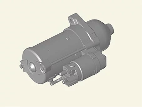
Starter Components and Components Location
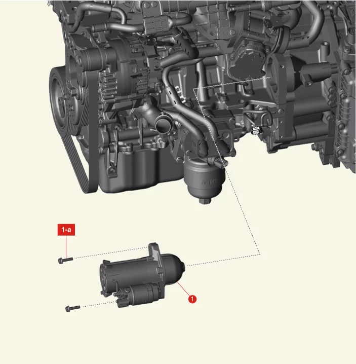
1. Starter
1-a. 49.0 - 63.7 N·m (5.0 - 6.5
kgf·m,
36.2 - 47.0 lb·ft)
|
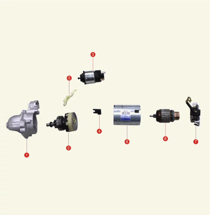
1. Starter Front Bracket
2. Reduction
Pinion
Gear
3. Magnetic Switch Assembly
4. Lever Packing
|
5. Lever
6. Yoke Assembly
7. Brush
Holder
Assembly
8. Armature Assembly
|
Starter Description and Operation
|
•
|
Starter consist of solenoid, brush holder, armature assembly, reduction pinion gear etc.
|
|
•
|
When the turn on the START, the current flows and is applied to the starter solenoid coil.
|
|
•
|
When supplying the current, engine is cranking after the solenoid plunger and shift lever are
moved, and
the reduction pinion gear inter lock to the ring gear.
|
|
•
|
To prevent damage from excessive rotation of the armature when starting, the pinion gear clutch
overruns.
|
Starter Removal and Installation
| 1.
|
Disconnect the battery negative ( - ) terminal.
|
| 2.
|
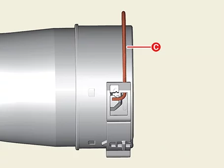
Separate the air intake hose (A).
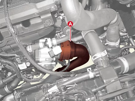
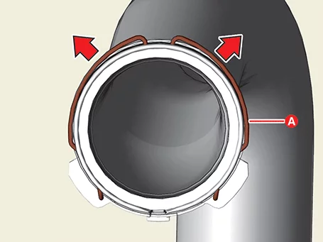
| 1) |
Pull the quick-connector clamp (A) in the direction of the
arrow when separating the air
intake hose.
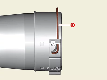
|
| 2) |
After moving the quick connector clamp (B) to (C) position as
shown in the figure below,
pull out the air intake hose to separate it.
|
|
|
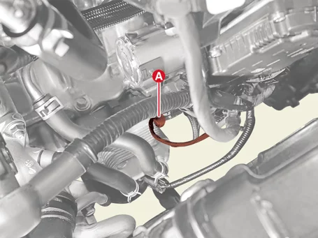
| 3.
|
Disconnect the starter connector (A).
|
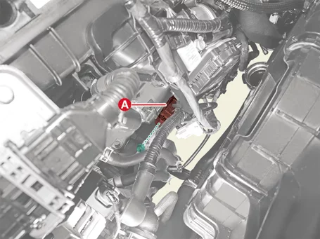
| 4.
|
Remove the starter B terminal cable (A) after removing the nut.
|
Tightening torque :
11.8 - 14.7 N·m (1.2 - 1.5 kgf·m , 8.7 - 10.8 lb·ft)
|
|
| 5.
|
Remove the engine room under cover.
(Refer to Engine Mechanical System - "Engine Room Under
Cover")
|
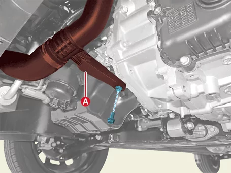
| 6.
|
Separate the intercooler outlet hose (A) after removing the bolt.
|
Tightening torque :
9.8 - 11.8 N·m (1.0 - 1.2 kgf·m, 7.2 - 8.7 lb·ft)
|
|
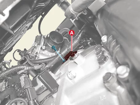
| 7.
|
Remove the wiring bracket (A) after removing the bolt.
|
Tightening torque :
9.8 - 11.8 N·m (1.0 - 1.2 kgf·m, 7.2 - 8.7 lb·ft)
|
|
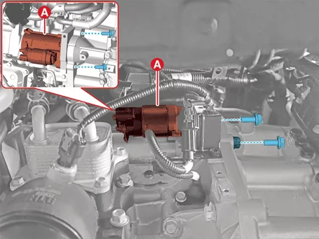
| 8.
|
Remove the starter (A) after removing the bolts.
|
Tightening torque :
49.0 - 63.7 N·m (5.0 - 6.5 kgf·m, 36.2 - 47.0 lb·ft)
|
|
| 1.
|
Install in reverse order of removal.
|
•
|
Install the starter to the specified torque.
|
|
•
|
If the starter is dropped, it may cause internal damage. (Do
not reuse)
|
|
|
Starter Disassembly and Reassembly
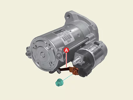
| 1.
|
Separate the solenoid M terminal (A) after removing the nut.
|
Tightening torque :
9.8 - 11.8 N·m (1.0 - 1.2 kgf·m, 7.2 - 8.7 lb·ft)
|
|
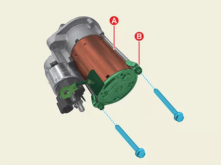
| 2.
|
Remove the york & armature assembly (A) and rear bracket (B) after removing the bolts.
|
| 3.
|
Separate the magnetic switch assembly (A) after removing the screws.
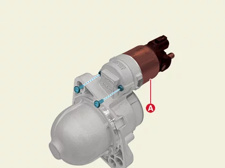
|
| 4.
|
Separate the magnetic switch assembly (B) and lever (C), pinion gear (D) by removing the lever
packing
(A).
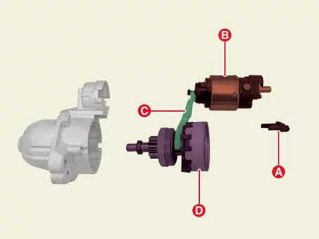
|
| 5.
|
Separate the yoke assembly (A) and armature & brush holder assembly (B).
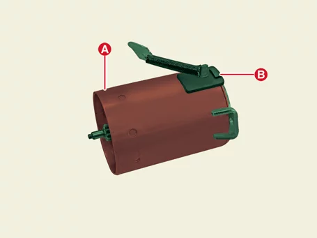
|
| 6.
|
Separate the armature (A) and brush holder (B).
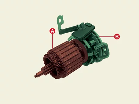
|
| 1.
|
Reassemble in the reverse order of disassembly.
|
Starter Inspection
Magnetic Switch Assembly Plunger Inspection
| 1.
|
Separate the solenoid M terminal (A) after removing the nut.
|
Tightening torque :
9.8 - 11.8 N·m (1.0 - 1.2 kgf·m, 7.2 - 8.7 lb·ft)
|
|
| 2.
|
Connect the 12 V battery between the solenoid terminal and starter body.
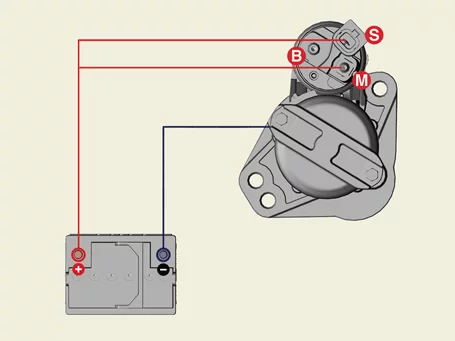
|
To avoid damaging the coil, perform the test within 10 seconds.
|
|
| 3.
|
Replace the starter when pinion gear does not move outside.
|
| 4.
|
Disconnect the cable from solenoid M terminal.
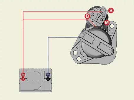
|
To avoid damaging the coil, perform the test within 10 seconds.
|
|
| 5.
|
The hold-in coil is normal if the pinion gear does not move to outside.
|
| 6.
|
Disconnect the cable from starter body.
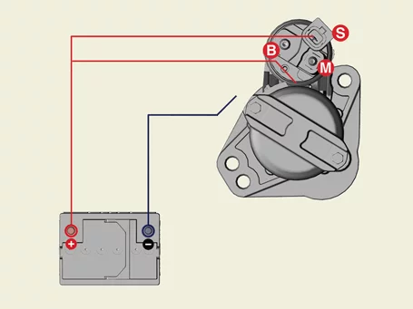
|
To avoid damaging the coil, perform the test within 10 seconds.
|
|
| 7.
|
Replace the starter when pinion gear does not move to inside.
|
Starter Motor Operation Inspection
| 1.
|
Connect the 12 V battery between the solenoid terminal and starter body.
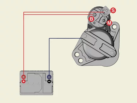
|
To avoid damaging the coil, perform the test within 10 seconds.
|
|
| 2.
|
Replace the starter when starter motor does not operate.
|
Free Running Inspection
| 1.
|
Place the starter motor in a vise equipped with soft jaws and connect a fully-charged 12 V
battery to
starter as follows.
|
| 2.
|
Connect a test ammeter (100 A) and rheostat shown as the illustration.
|
| 3.
|
Connect a voltmeter (15 V) across starter.
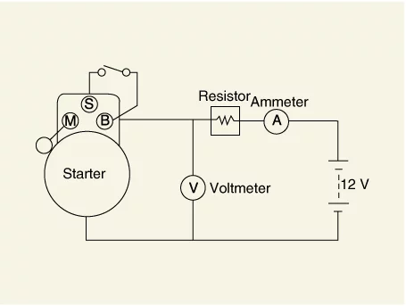
|
| 4.
|
Rotate rheostat to the OFF position.
|
| 5.
|
Connect the battery cable from the battery negative ( - ) terminal to the starter.
|
| 6.
|
Adjust so that the battery voltage indicated by the voltmeter is 11.5 V.
|
| 7.
|
Confirm that the maximum amperage is within the specifications and the starter motor turns
smoothly and
freely.
|
Ampere (A) : Maximum 83.6
Speed (rpm) : Minimum 3,500
|
|
Starter Cleaning
| 1.
|
Do not immerse the yoke assembly or armature assembly in solvents as it may cause the damage in
the
insulation. Use a cloth to clean the parts.
|
| 2.
|
Do not clean or immerse the reduction pinion gear with a solvent as it is lubricated.
|
| 3.
|
All parts except the operating parts can be cleaned with a brush moistened with solvent and
then wipe
them with dried cloth.
|
Starter Relay Inspection
| 1.
|
Disconnect the battery negative ( - ) terminal.
|
| 2.
|
Remove the engine room junction block cover (A).
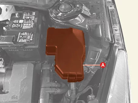
|
| 3.
|
Remove the starter relay (A).
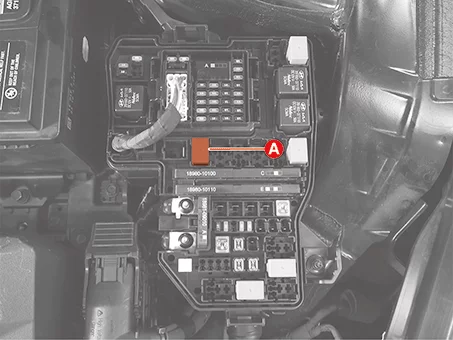
|
| 4.
|
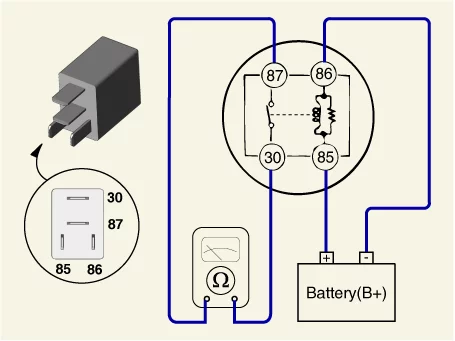
Check for continuity between the terminals (30 and 87) using an ohmmeter.
Terminal
|
Resistance
|
Measure
|
30 - 87
|
1 MΩ or above
|
If there is continuity between the terminals, replace the
relay.
|
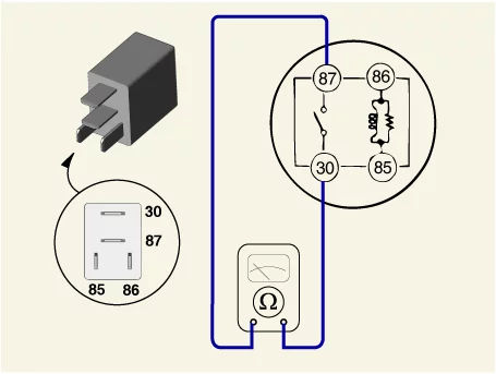
|
| 5.
|
Apply 12 V to the terminal 85 and ground to the terminal 86 and then check for continuity
between the
terminals (30 and 87).
Terminal
|
Resistance
|
Measure
|
30 - 87
|
1 Ω or below (About 0 Ω)
|
If there is no continuity between the terminals, replace the
relay.
|
|
| 6.
|
Install in the reverse order of removal.
|
Other information:
Kia K4 (CL4) 2025-2026 Service Manual: Ignition switch:
LOCK
ACC
ON
START
LOCK
In this position, the Kia K4 steering wheel is mechanically locked to deter theft.
Kia K4 (CL4) 2025-2026 Service Manual: Audio system
The audio system in your Kia K4 is engineered for high-fidelity performance. To ensure the longevity and proper operation of all infotainment components, please adhere to the following guidelines regarding vehicle modifications and accessories.
NOTE
We strongly advise against the installation of aftermarket High Intensity Discharge (HID) headlight kits.