Contents:
Description and Operation
|
•
|
Ignition timing is controlled by electronic ignition system, and standard ignition timing data
according
to the engine operating condition is stored in the Engine Control Module (ECM).
|
|
•
|
Engine operation conditions (speed, load, temperature) are detected by various sensor. Based on
these
sensors ignition timing data, the primary current cut-off signal is received from the ECM to
activate the
ignition coil and control the ignition timing.
|
Troubleshooting
Engine won't start or is hard to start (cranks OK)
Suspected Cause
|
Correction
|
Start / stop button fault
|
Inspect or replace start / stop button
|
Ignition coil fault
|
Inspect and replace the ignition coil
|
Spark plug fault
|
Inspect and replace the spark plug
|
Ignition wiring disconnected or broken
|
Repair or replace the wiring
|
Rough idle or stalls
Suspected Cause
|
Correction
|
Ignition wiring fault
|
Repair or replace the wiring
|
Ignition coil fault
|
Inspect and replace the ignition coil
|
Engine hesitates or poor acceleration
Suspected Cause
|
Correction
|
Spark plug fault
|
Inspect and replace the spark plug
|
Ignition wiring fault
|
Repair or replace the wiring
|
Poor fuel efficiency
Suspected Cause
|
Correction
|
Spark plug fault
|
Inspect and replace the spark plug
|
Ignition Coil Specification
Item
|
Specification
|
Rated voltage (V)
|
14
|
Operating voltage (V)
|
4 - 16
|
Engine speed (rpm)
|
1,000
|
2,000
|
3,000
|
4,000
|
5,000
|
6,000
|
7,000
|
Dwell time (ms)
|
5.9
|
5.2
|
4.2
|
3.8
|
3.5
|
3.2
|
2.3
|
Secondary coil voltage (kV)
|
40
|
40
|
40
|
40
|
39
|
38
|
31
|
Ignition Coil Components and Components Location
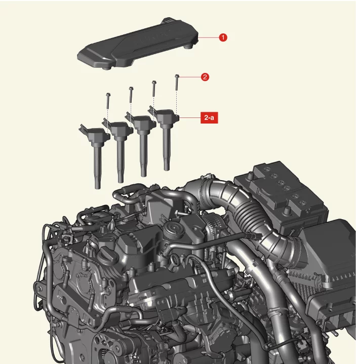
1. Engine Cover
|
2. Ignition Coil
2-a. 9.8 - 11.8 N·m (1.0 -
1.2
kgf·m, 7.2 - 8.7 lb·ft)
|
Ignition Coil Description and Operation
|
•
|
The ignition coil is a small transformer that transforms the battery voltage to 30 kV or more
to create a
spark in the spark plug gap in the cylinder.
|
|
•
|
The igniter built into the ignition coil includes the power transistor and it is an electronic
switch
whose electric current is controlled by the Engine Control Module (ECM) signal.
|
|
•
|
The ignition timing is controlled by the ECM and the standard ignition timing data according to
engine
operating condition is stored in the ECM memory.
|
|
•
|
The engine operating conditions (speed, load, warm-up state, etc.) are detected by the various
sensors.
Based on these sensor signals and the ignition timing data, when the ECM applies the ignition
signal to the
ignition coil for a certain period of time, the igniter is energized. As the current flows and
rises
gradually to the primary coil and the magnetic field is produced.
|
|
•
|
When the current in the primary coil is cut off by the ignition signal of the ECM, the rapid
change of
the magnetic flux by the mutual induction action is induced to the secondary coil and high
voltage is
generated depending on the coil winding ratio.
|
|
•
|
This high voltage generated from the secondary coil is caught in the spark plug gap and
discharges as the
electric field is destroyed to generate a spark.
|
Ignition Coil Troubleshooting
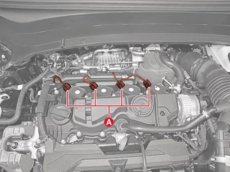
Connector connection condition test
| 1.
|
Disconnect the battery negative ( - ) terminal.
|
| 2.
|
Remove the engine cover.
(Refer to Engine Mechanical System - "Engine Cover")
|
| 3.
|
Re-connect the ignition coil connectors (A) after disconnecting the ignition coil connectors.
|
| 4.
|
Connect the battery negative ( - ) terminal.
|
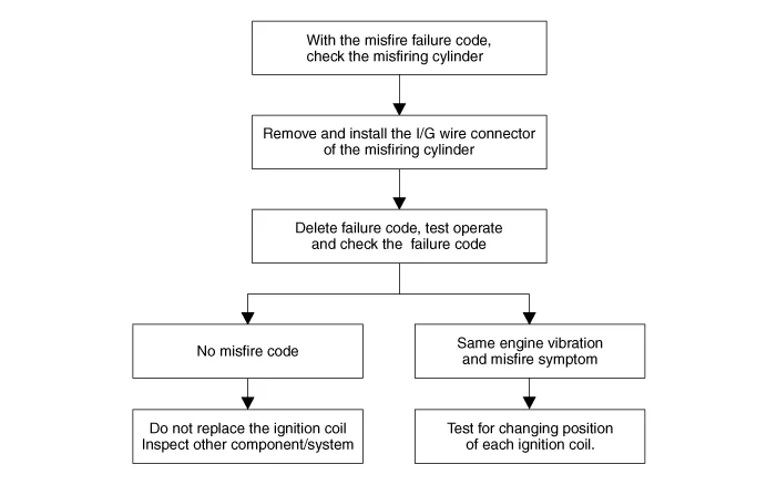
| 5.
|
Perform driving test after deleting the DTC code.
|
Test for changing position of each ignition coil
| 1.
|
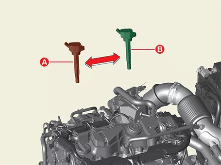
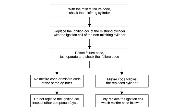
Change the misfired ignition coil (A) and normal ignition coil (B).
(Refer to Ignition Coil - "Removal and Installation")
|
Do not move with spark plug at the same time. (move the ignition coil only)
|
|
| 2.
|
Perform driving test after deleting the DTC code.
|
Ignition Coil Removal and Installation
| 1.
|
Disconnect the battery negative ( - ) terminal.
|
| 2.
|
Remove the engine cover.
(Refer to Engine Mechanical System - "Engine Cover")
|
| 3.
|
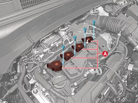
Disconnect the ignition coil connectors (A).
|
| 4.
|
Remove the ignition coils (A) after removing the bolts.
|
Tightening torque :
9.8 - 11.8 N·m (1.0 - 1.2 kgf·m, 7.2 - 8.7 lb·ft)
|
|
| 1.
|
Install in reverse order of removal.
|
•
|
Install the ignition coil to the specified torque.
|
|
•
|
If the ignition coil is dropped, it may cause internal damage.
(Do not reuse)
|
|
•
|
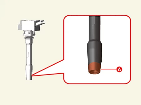
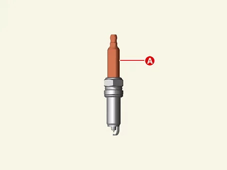
When installing the parts, use cloth to clean the contaminated
area (A).
- Use a clean and soft cloth to avoid damage.
(When replacing ignition coil and spark plug together, cleaning
is not required.)
|
|
|
Spark Plug Specification
Item
|
Specification
|
Type
|
SILZKR8J8GS
|
Plug gap [mm (in.)]
|
0.7 - 0.8 (0.0276 - 0.0315)
|
Spark Plug Components and Components Location
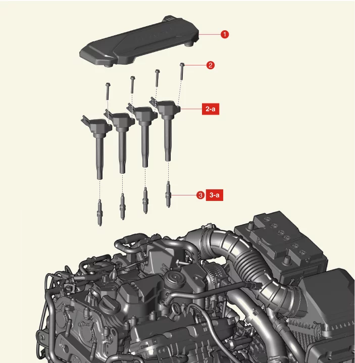
1. Engine Cover
2. Ignition Coil
2-a.
9.8 - 11.8
N·m (1.0 - 1.2 kgf·m, 7.2 - 8.7 lb·ft)
|
3. Spark Plug
3-a. 14.7 - 24.5 N·m (1.5 -
2.5
kgf·m, 10.8 - 18.1 lb·ft)
|
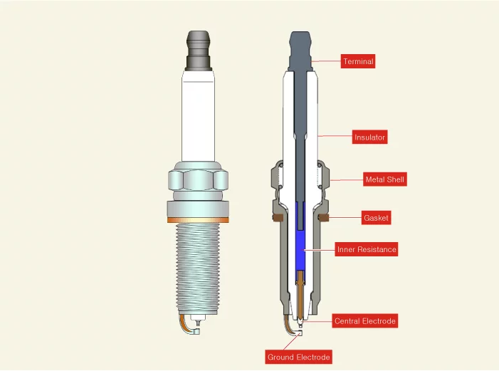
Spark Plug Description and Operation
The high voltage generated by the ignition system ignites the air mixed with the fuel at an appropriate time,
and
the pressure generated by the explosion of the mixture operates the piston to drive the engine.
Spark Plug Troubleshooting
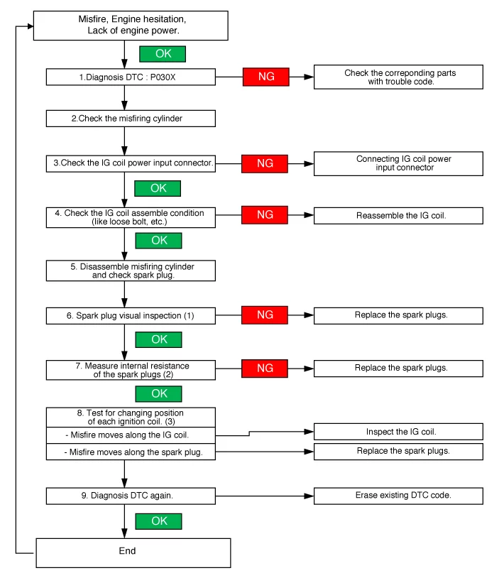
| 1.
|
Check the DTC code with the KDS. (Refer to "DTC guide")
|
| 2.
|
Check the ignition coils.
(Refer to Ignition System - "Ignition Coil")
| (1)
|
Check the ignition coil connector.
|
| (2)
|
Check the ignition coil installation state.
|
Tightening torque :
9.8 - 11.8 N·m (1.0 - 1.2 kgf·m, 7.2 - 8.7 lb·ft)
|
|
|
| 3.
|
Remove the spark plug.
(Refer to Spark Plug - "Removal and Installation")
|
| 4.
|
Visually inspect the external spark plugs.
|
Plug gap [mm (in.)] : 0.7 - 0.8 (0.0276
- 0.0315)
|
Symptom
|
Suspected Cause
|
Correction
|
|
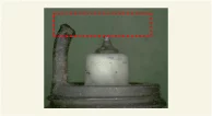
Melting electrode
|
Abnormal combustion, Overheat
|
Replace the spark plug
|
|
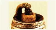
Carbon and foreign matter
|
|
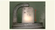
Ring crack
|
Abnormal combustion, External shock
|
|
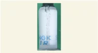
Vertical crack
|
External shock
|
|
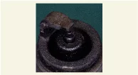
Overheat
|
Abnormal combustion
|
Symptom
|
Suspected Cause
|
Correction
|
|
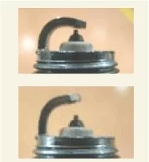
Poor gap
|
Physical damage
|
Replace the spark plug
|
|

Flash over
|
Excessive electrode wear
|
Replace the spark plug, ignition coil
|
|
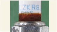
Corrosion/Rust
|
Remaining oil mist
|
Reassemble the spark plug
|
|
| 5.
|
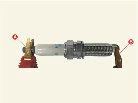
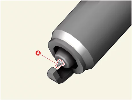
Check the resistance between the spark plugs terminal (A) and probe (B) by using a multi-tester
or a
resistance meter.
|
Specified value (kΩ) : 2 - 20
|
|
•
|
Avoid the contact resistance between probe and spark plugs.
(when it occurs, the measured
value is not stabilized)
|
|
•
|
Be careful not to damage center electrode (A) while measuring
resistance.
|
|
|
| 6.
|
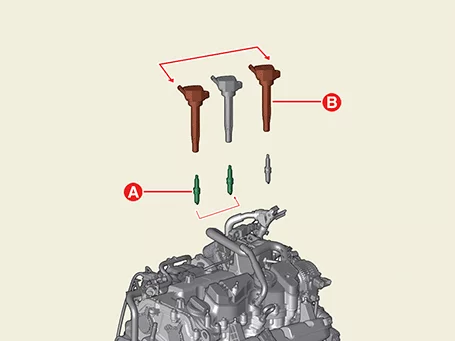
Test for changing position of each ignition coil and spark plug.
| 1) |
Remove the spark plug (A) and ignition coil (B) from the misfiring cylinder and
exchange them
with one of the other cylinders.
(Refer to Spark Plug - "Removal and
Installation")
|
| 2) |
Replace the spark plugs, if misfire moves along the spark plugs.
|
|
Spark Plug Removal and Installation
| 1.
|
Remove the ignition coil.
(Refer to Ignition System - "Ignition Coil")
|
| 2.
|
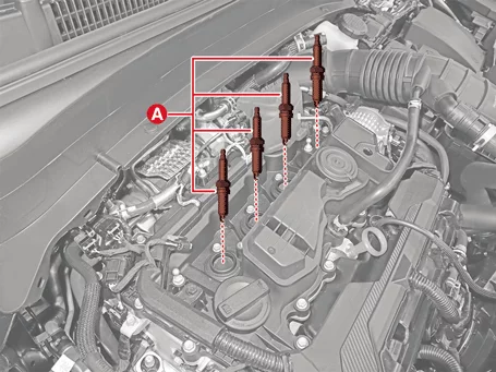
Remove the spark plugs (A) by using a spark plug socket.
|
Tightening torque :
14.7 - 24.5 N·m (1.5 - 2.5 kgf·m, 10.8 - 18.1 lb·ft)
|
|
Be careful not to get foreign matter into the spark plug hole.
|
|
| 1.
|
Install in reverse order of removal.
|
•
|
Install the spark plug to the specified torque.
|
|
•
|
Be careful not to damage the electrode when installing the
spark plug.
|
|
•
|
If the spark plug is dropped, it may cause internal damage. (Do
not reuse)
|
|
•
|
When installing the parts, use cloth to clean the contaminated
area (A).
- Use a clean and soft cloth to avoid damage.
(When replacing ignition coil and spark plug together, cleaning
is not required.)
|
|
|
Spark Plug Cleaning
Incomplete combustion builds up carbon deposits and fuel accumulates in the spark plug. Therefore combustion
becomes temporarily unstable, and cleaning should be performed as below.
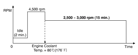
| 1.
|
Start the engine and keep the engine running at idle for 2 minutes.
|
| 2.
|
Place the shift lever in N and press the accelerator to maintain engine rpm at 4,500.
Warm up the engine until engine coolant temperature reaches at 80°C (176°F).
|
| 3.
|
Keep the engine running at 2,500 - 3,000 rpm in the N position for 15 minutes.
|
|
If [1st Method] does not work properly, perform the cleaning with [2nd Method].
|
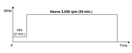
| 1.
|
Start the engine and keep the engine running at idle for 2 minutes.
|
| 2.
|
Drive the vehicle for over 20 minutes and keep the engine speed above 3,500 rpm.
|
Other information:
Kia K4 (CL4) 2025-2026 Service Manual: Troubleshooting
Troubleshooting
•
Be careful not to short-circuit the wiring by the vehicle body or other wiring.
Kia K4 (CL4) 2025-2026 Service Manual: Immobilizer system
The advanced electronic immobilizer system integrated into your vehicle serves as a primary layer of security, designed to protect your vehicle from unauthorized use and potential theft. This anti-theft configuration relies on an encrypted transponder chip embedded within your official smart key. If an improperly coded key, cloned fob, or any unauthorized bypass device is detected during an ignition sequence, the system immediately cuts off fuel delivery and ignition signals, ensuring that the vehicle's powertrain and electrical power system are completely disabled.