Contents:
Tire Inspection
| 1.
|
Measure the tread depth of the tires.
|
Tread depth [Limit] :1.6 mm (0.062
in.) [High Speed Vehicle : 2.4 mm (0.09
in.)]
|
|
| 2.
|
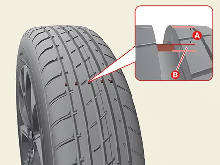
Replace the tire when the tread depth (A) is less than the wear indicator (B).
|
If the tread depth is less than 1.6 mm (0.062 in.) [High Speed Vehicle: 2.4 mm
(0.09 in.)] the
wear indicator (B) appears.
|
|
Tire Removal
| 1.
|
Remove the wheels and tires.
(Refer to Wheel and Tire - "Wheel")
|
| 3.
|
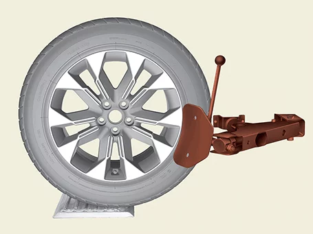
Remove the tire from the wheel using the tire replacing equipment.
|
Remove the bead at away 90º, 180º, and 270º from the valve.
|
|
| 4.
|
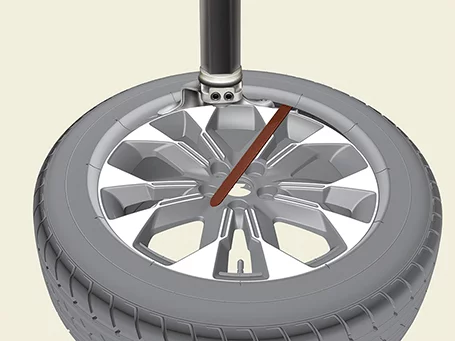
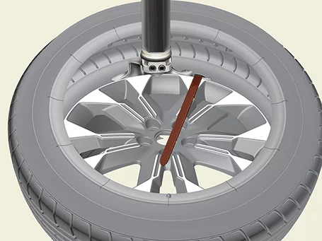
Remove the tire by levering it and rotating the wheel clockwise.
|
Tire Installation
| 1.
|
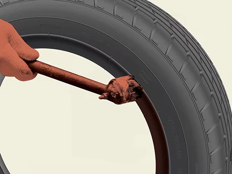
Lubricate the tire bead side using tire mounting lubricant.
|
Specified Lubricant : Soapy water or
YH100 (Lubricants
for tire assembling)
|
|
| 2.
|
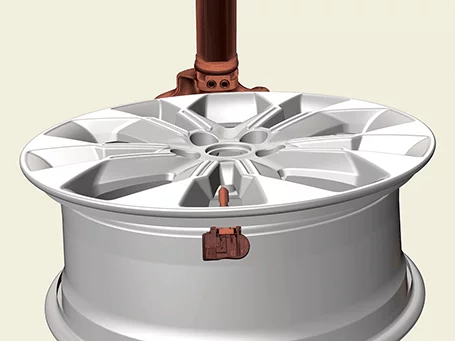
Place the tire replacement machine to installing the bottom bead.
|
| 3.
|
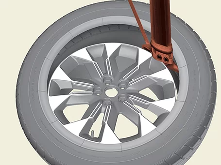
Rotate the rim clockwise, and push down on the tire at the 3 o’clock position to install the
bottom bead.
|
| 4.
|
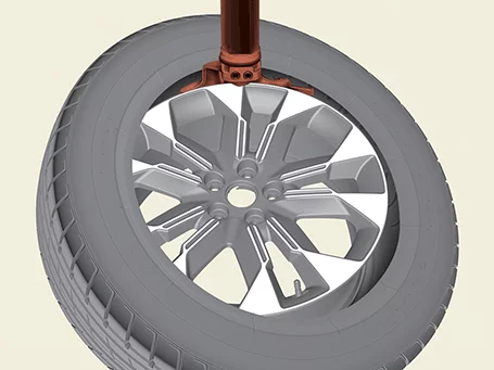
Push down the tire at 3 o'clock position and then rotate the rim clockwise to install the upper
bead.
|
| 5.
|
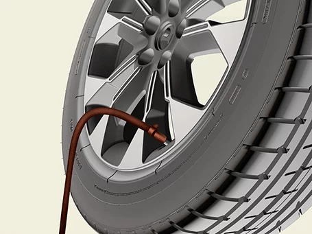
Inflate the tire until the beads fit.
Tire Pressure
Tire Size
|
Tire Pressure [kPa (psi)]
|
Front
|
Rear
|
205/55 R16
|
Steel wheel
|
250 (36)
|
230 (33)
|
Aluminum wheel
|
235 (34)
|
215 (31)
|
225/45 R17
|
235/40 R18
|
230 (33)
|
|
| 6.
|
Install the wheels and tires.
(Refer to Wheel and Tire - "Wheel")
|
Tire Replacement
|
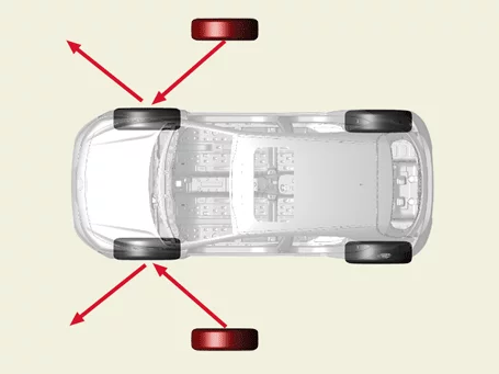
Changing directional or asymmetric tires left/right and diagonally may result in poor driving
and braking
performance.
|
Replace the tire in the direction shown by the arrow in the figure below.
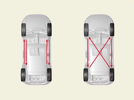
Rotating For Pull And Wander
If the vehicle is pulled to one side without any particular symptoms of failure, tire wear may be the cause.
In this case, the following tire replacement procedures shall be performed.
| 1.
|
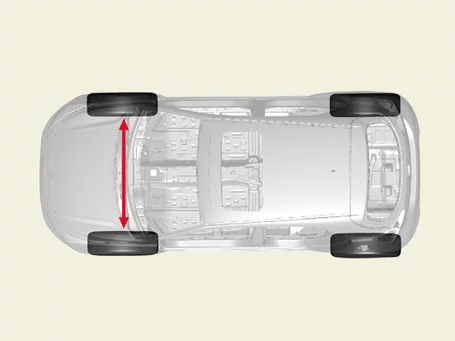
Rotate the front right and front left tires, and perform a road test in order to confirm
vehicle
stability.
|
| 2.
|
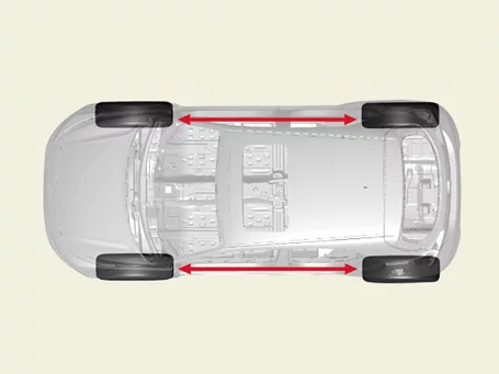
If the steering pulls to the opposite side, rotate the front and rear tires, and perform a road
test
again.
|
| 3.
|
If the steering continues to pull to one side, rotate the front right and left tires again, and
perform a
road test.
|
| 4.
|
If the steering continues to pull to the opposite side, replace the front wheels with new ones.
|
Wheel Removal and Installation
| 1.
|
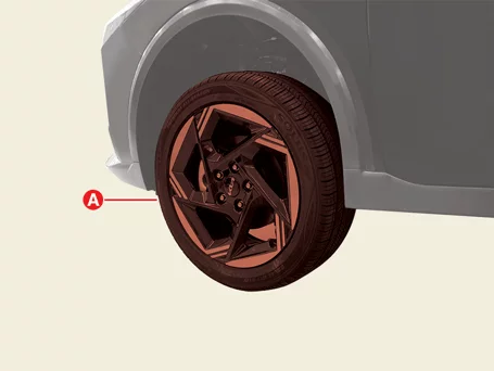
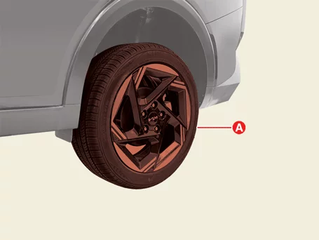
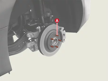
Remove the wheel and tire (A).
|
Tightening torque :
107.9 - 127.5 N·m (11.0 - 13.0 kgf·m, 79.6 - 94.0 lb·ft)
|
[Front]
[Rear]
|
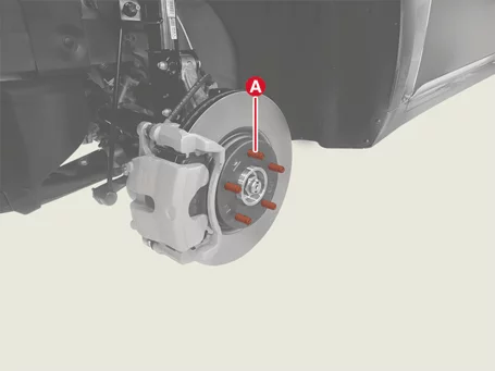
Be careful not to damage the hub bolts (A) when removing the wheel and tires.
[Front]
[Rear]
|
|
| 1.
|
Install the wheel and tire (A).
|
Tightening torque :
107.9 - 127.5 N·m (11.0 - 13.0 kgf·m, 79.6 - 94.0 lb·ft)
|
[Front]
[Rear]
|
•
|
Be careful not to damage the hub bolts (A) when installing the
wheel and tires.
[Front]
[Rear]
|
|
•
|
Tighten the hub nuts as follows.
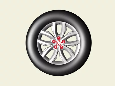
|
|
•
|
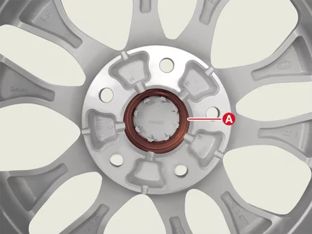
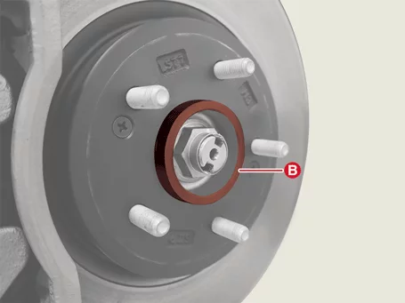
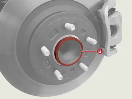
Remove rust or debris from the contact surface of the wheel
side (A) and the hub side (B)
and install the wheels and tires.
[Front]
[Rear]
|
|
•
|
When using an impact gun, final tightening torque should be
checked using a torque
wrench.
|
|
|
Wheel Inspection
| 1.
|
Jack up the vehicle and support with a jack securely.
|
| 2.
|
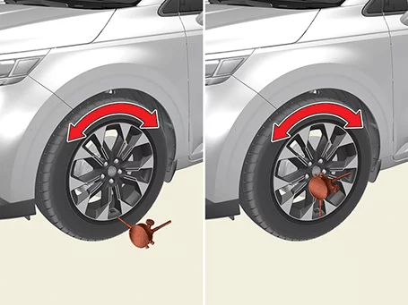
Measure the wheel Run-out by using a dial indicator as illustration below.
Limit
|
Circumferential
|
Axial
|
Run-out
|
Aluminium Wheel
|
0.3 mm (0.0118 in.)
|
0.3 mm (0.0118 in.)
|
|
| 3.
|
If measured value exceeds the standard value, replace the wheel.
|
Wheel Balance Description and Operation
Symptoms of Defective Wheel Balance
If the wheel balance is defective
|
1. Steering wheel vibration occurs.
|
2. Road impact is transmitted to the steering wheel during driving.
|
3. Irregular tire wear occurs.
|
4. Driving vibration decreases ride comfort.
|
Types of Wheel Imbalance
|
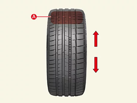
Symptoms of Defective Static Balance(If the tire weight is applied to only one side)
|
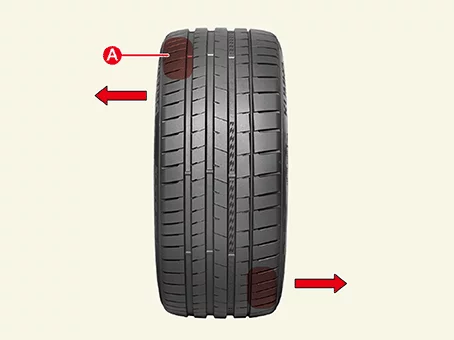
Symptoms of Defective Dynamic Balance(If the tire weight is not applied equally to left
and right
sides)
|
|
|
|
•
|
The tire bounces vertically.
|
|
|
|
•
|
The tire wobbles from side to side.
|
|
•
|
Effect on steering and driving stability.
|
|
Types of Wheel Balance
|
Road Balancing
|
Road Force Balancing
|
|
If the imbalance symptoms occur due to defective wheel balance after road balancing, do
road force
balancing.
|
Inspection and Adjustment Procedure
|
|
•
|
Install the tire on the balancing equipment. Examine the tire balance.
|
|
•
|
When imbalance occurs, turn the tire as shown on the screen. Attach the balance
weight to the
wheel for adjustment.
|
|
|
•
|
Install the tire on the balance equipment. Examine the road force balance.
|
|
•
|
When imbalance occurs, attach the balance weight at the position marked by the
red laser.
|
|
Wheel balance equipment
|
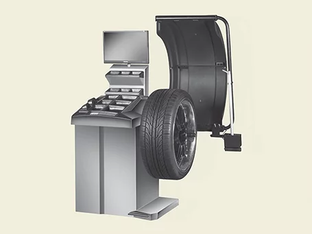
|
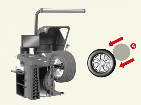
|
|
–
|
Tire road balancing is a procedure to examine and adjust that the weight of the tire and wheel
is equally
applied around the rotation axis during turning.
|
|
–
|
Do road balancing if tire wear is irregular, the steering wheel vibrates, or the tire is
replaced.
|
|
–
|
If imbalance is caused by irregular weight distribution, install balance weight on the wheel to
adjust
the weight.
|
|
–
|
If road balancing does not correct the problem, do road force balancing.
|
|
–
|
Road force balancing is a accurate procedure that applies vertical load to the tire under
conditions
equivalent to actual driving. It measures and adjusts imbalances caused by tire deformation and
lateral
wobble that cannot be identified by standard balancing.
|
|
–
|
Do road force balancing if tire wear is irregular, the steering wheel vibrates, or the tire is
replaced.
|
|
–
|
If imbalance is caused by unbalanced weight distribution, install the balance weight on the
wheel at the
position marked by the red laser.
|
|
–
|
If road force balancing does not correct the problem, damage to the wheel or a tire defect can
be
predicted.
|
Wheel Balance Inspection
Wheel balance needs to be adjusted if the tires are unbalanced or after tire replacement or maintenance work
has
been performed.
|
Maximum rim unbalance weight : 2.12 oz (60 g)
|
|
•
|
If the maximum unbalance weight over than 3.53 oz (100g), reassemble the wheel
and tire, then
perform the wheel balance adjustment.
|
|
•
|
Make sure that the wheel and tire install in the balancer securely.
|
|
•
|
For details, refer to the instructions of each balancer.
|
|
•
|
Use flange type balance lead (A) or non-flange type balance lead (B) depending
on wheel flange
type.
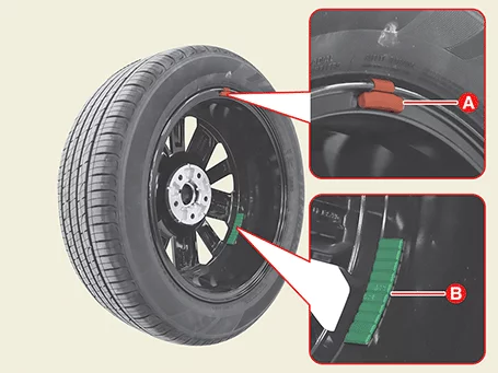
|
|
Other information:
Kia K4 (CL4) 2025-2026 Service Manual: Recommended Lubricants and Capacities for Kia K4
To help achieve proper engine and powertrain performance, maximum fuel efficiency, and long-term mechanical durability for your vehicle, use only the explicitly correct lubricants. Selecting the right fluids for your Kia K4 also promotes optimal engine thermal efficiency, which directly improves fuel economy and reduces emissions. Always ensure the following certified high-grade lubricants and technical fluids are utilized during your Kia K4 routine maintenance cycles:
Fluid / Lubricant Type
Fill Capacity (Volume)
Industry Standard / Classification
Engine Oil(Complete drain and oil filter refill volume)
Smartstream G2.
Kia K4 (CL4) 2025-2026 Service Manual: Manual Speed Limit Assist (MSLA)
Speed Limit indicator
Set speed value
The Manual Speed Limit Assist (MSLA) feature in your Kia K4 allows you to establish a maximum speed limit to prevent the vehicle from inadvertently exceeding your desired pace.