Contents:
Components and Components Location
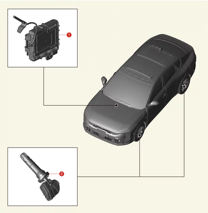
1. Body Domain Control Unit
|
2. Tire Pressure Monitoring System (TPMS)
Sensor
|
Description and Operation
The tire pressure monitoring system continuously monitors the pressure and temperature inside the tire to warn
of
changes in the pressure inside the tire that may affect the driving conditions of the vehicle. The TPMS control
module analyzes information from the Wheel Electronic (WE) sensor mounted inside the wheel, determines the tire
condition, and outputs a signal necessary for controlling the warning lamp.
Tire Low Pressure Light
TPMS light ON/OFF conditions
| 1.
|
Lamp ON Conditions
|
•
|
The lamp turns ON when the tire pressure decreases below the standard level.
|
|
| 2.
|
Lamp OFF
|
•
|
Low pneumatic pressure: The warning lamp turns OFF when the tire pressure
exceeds the pressure
required to turn off the lamp.
|
|
TPMS Fault Warning Lamp
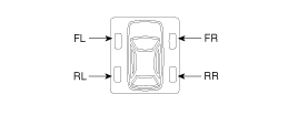
| 1.
|
Lamp ON Conditions
|
•
|
It on simultaneously with the tread lamp.
|
|
•
|
It Indicates the position of tires with low pressure and air leaks.
|
|
| 2.
|
Lamp OFF
|
•
|
OFF simultaneously with the tread lamp.
|
|
If the wheel position changes while driving, the system assumes the previous
state, but the
warning light illuminates correctly when the current driving position is
determined.
|
|
•
|
Tread warning lights and wheel position warning lights may
light up due to sudden changes
in the outside temperature (especially in winter) and influences
from driving.
|
|
•
|
When the warning lamp turns on, check the inflation pressure
and then inflate it to the
specified tire pressure.
|
|
|
TPMS Warning Light
| 1.
|
Warning Conditions and Display
|
•
|
When the system detects a fault outside the receiver or sensor, it blinks for
about 1 minute and
then turns on.
|
|
•
|
When the system detects a receiver fault, it blinks for about 1 minute and then
turns on.
|
|
•
|
When the system detects a sensor fault, it blinks for about 1 minute and then
turns on.
|
|
| 2.
|
Lamp OFF
|
•
|
When the DTC is resolved, the warning light turns off, and the DTC is saved as
a past fault.
|
|
•
|
If this happens while driving, even if the DTC has been
resolved, it should be checked
again.
(IG OFF and ON, then check the warning light again)
|
|
•
|
The warning lamp turns off once the DTC is resolved. The
warning lamp stays on until you
complete the check necessary to resolve the DTC.
|
|
•
|
If the DTC is resolved, the warning lamp turns OFF during the
same ignition cycle.
|
|
If the vehicle starts within 19 minutes after the replacement of the wheel of
the stopped
vehicle, the TPMS Malfunction Indicator on the instrument cluster illuminates.
|
–
|
The above symptom is due to communication failure between the
BCM and the replaced TPMS
ID.
|
|
–
|
This communication failure indicator turns off in 19 minutes
after the vehicle stops
through the BCM’s automatic learning process of TPMS ID.
(When driving the vehicle after stopping for over 19 minutes,
the indicator turns off
automatically.)
|
|
|
System fault
| 1.
|
General Function
|
•
|
The system detects many input elements to identify potential defects.
|
|
•
|
The priority of a defect depends on its cause.
|
|
•
|
Certain defects are not diagnosed as DTCs.
|
The following are major defects:
| a. |
In order to diagnose more symptoms of the fault when the ignition line
malfunctions, you must
check the warning lamp when you turn the ignition on.
|
| b. |
Check whether the warning lamp turns on and then off.
|
|
TPMS Receiver Description and Operation
TPMS monitors the pressure and temperature of tires to warn of pressure changes that may affect driving
conditions.
The messages calculated from the processed data are shown in the cluster through one warning lamp.
Also, checking the ECU input and output signals by ERROR.
And receive pressure data sensored while parking.
The ECU processes the data received from the wheel sensors, determines the condition of the tires, and delivers
the required warning messages to the driver via the CAN line or hardwire control line.
TPMS Receiver : Integrated with BDC (Body Domain Control) Unit.
| 1.
|
Initial state
|
•
|
Platform information and sensor ID are not entered.
|
|
| 2.
|
Normal operation state
|
•
|
In order to detect tire pressure and DTC, the receiver must be in normal
operation.
|
|
•
|
The receiver can check the sensor location and data.
|
|
| 1.
|
General Function
|
•
|
Auto-learn takes place only once per ignition cycle.
|
|
•
|
On successful completion, 4 road wheel sensor ID's are stored into memory for
monitoring.
|
|
•
|
Until auto-learn completes, previously learned sensors are monitored for under
inflation / leak
warnings.
|
|
•
|
Temporary tire pressure expansion and DTC status are not indicated.
|
|
| 2.
|
General conditions for learning new sensors
|
•
|
Automatic learning only operates at speeds above 25 km/h (15.5 mph).
|
|
•
|
The typical time it takes to learn a new sensor is up to 10 minutes at speeds
of 25 km/h (15.5
mph) or more.
|
|
| 3.
|
General conditions for deleting learning about the removed sensor.
|
•
|
Drive at a speed of 20 - 30 km/h (12.42 - 18.64 mph) for less than 10 minutes.
|
|
•
|
It depends on the vehicle speed or the number of sensors recorded in the
receiver.
|
|
TPMS Receiver On Vehicle Inspection
| 1.
|
Save the vehicle code, VIN, and sensor ID in the receiver and check whether it is properly
stored.
|
| 2.
|
Check that the status of the TPMS receiver (BDC, Body Domain Control Unit) is in normal
operation.
|
| 3.
|
Check whether the TPMS warning light is off and DTC code.
|
TPMS Receiver Removal and Installation
|
The TPMS receiver is integrated with the Body Domain Control (BDC) unit, so replace the BDC
unit.
|
| 1.
|
Replace the Body Domain Control (BDC) unit.
(Refer to Body - "Body Domain Control Unit")
|
TPMS Sensor Description and Operation
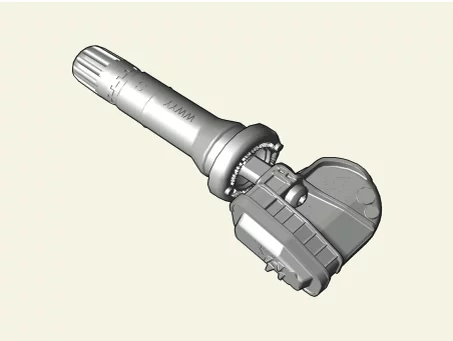
| 1.
|
Function
|
•
|
TPMS sensor (Transmitter) detects the motion and sends the pressure,
temperature data via RF
signal to ECU.
|
|
•
|
By comparing ABS wheel pulses with sensor RF signal transmission locations,
wheel automatic
position learning is conducted to recognize the corresponding wheel position.
|
|
| 2.
|
Configurations and Features
|
•
|
There are four (4) TPMS sensors mounted in each wheel of the vehicle.
|
|
•
|
The frequency conversion type is FSK, and the carrier frequency is 433.92 MHz.
|
|
| 3.
|
Mode
It consists of off mode, stop mode, rotation mode, and learning mode.
Illustration
|
Function
|
Valve type
|
Snap-in type [rubber valve]
|
Screw
|
Screw T10 [Continental Certified Parts]
|
ASIC
|
Gen 6
|
Battery type
|
CR2032 HR type
|
|
TPMS Automatic Location Learning
|
•
|
Wheel angular velocity of wheels are different from each other in the following cases:
|
| 1) |
Slip for each axis occurs differently.
|
| 2) |
Rotation radius (the radius of curve) for each wheel is different.
|
| 3) |
Tire wear, internal pressure, tire specifications, etc. for each tire are different.
|
|
•
|
TPMS sensor is transmitted to RF signal at only specific phase (the angle of the tire) in the
learning
mode.
|
|
•
|
TPMS receiver checks each tire phase (tire angle) information on receiving RF signals from the
sensor.
|
|
•
|
Every time RF signals from sensor IDs 1, 2, 3, and 4 are received, the ID with the highest
correlation
among the phase of each collected wheel is transmitted. (In other words, each time RF signal is
received,
the phase of the tire is transmitted to the most constant wheel.)
|
|
•
|
TPMS sensor transmits the RF signal at intervals of 16 seconds in the learning mode.
|
TPMS Automatic Location Operating
|
•
|
After stopping or parking for more than 19 minutes, automatic learning function in every
driving position
is performed.
|
|
•
|
The sensor is converted to Parking Mode when stopped or parked for more than 15 minutes. When
acceleration of over 4g (15-20 ㎞/h) is detected in Parking Mode, it is converted to First Block
Mode.
|
TPMS Sensor Inspection
How to inspect the tire pressure sensor after installation
After installation, the TPMS sensor installation normal and fault conditions are determined by the following
conditions:
[Normal]
| 1.
|
The rubber bulb of the valve is on the rim securely.
|
| 2.
|
The transmitter evenly spaced without touching the rim.
|
| 3.
|
The entire valve rib is pulled into the hall.
|
| 4.
|
The valve and rim holes forming the same axis.
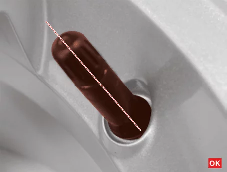
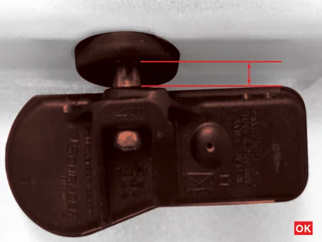
|
[Fault]
| 1.
|
The entire valve rib is not enough pulled into the hall.
|
| 2.
|
The rubber bulb of the valve is not on the rim securely.
|
| 3.
|
The valve and rim holes are not forming the same axis.
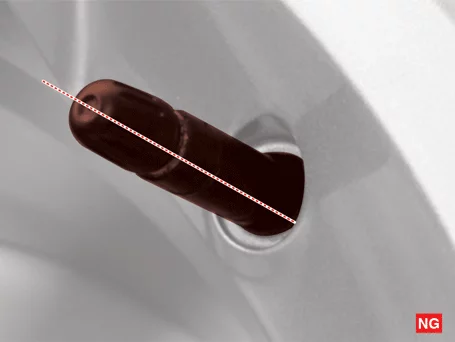
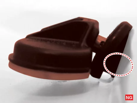
|
If the installation status is fault, remove and refit and check the installation status again.
TPMS Sensor Replacement
| 1.
|
Remove the tires.
(Refer to Wheel and Tire - "Tire")
|
| 2.
|
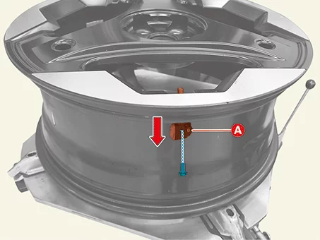
Remove the sensor housing (A) in the direction of the arrow after removing the screw.
|
•
|
When installing the bead brake, make sure that it does not come
in contact with the TPMS
sensor.
|
|
•
|
Be careful not to damage the TPMS sensor when installing the
bead brake near the TPMS
sensor.
|
|
|
| 3.
|
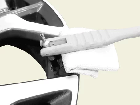
Using a valve mounting tool, pull the sensor housing through the hole.
|
| 4.
|
Apply the surface of the new valve with lubricant and install it in the valve hole of the
wheel.
|
Specified Lubricant : Soapy water or
YH100 (Lubricants
for tire assembling)
|
|
•
|
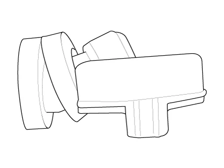
If the lower part of the TPMS sensor valve is not properly
mounted on the wheel as shown
below, sealing will not work properly.
|
|
•
|
All of the valleys of the valve body must be pulled through the
hole.
|
|
•
|
After applying lubricant, install the valve within 5 minutes.
(After 5 minutes, relubricate)
|
|
|
| 5.
|
Install the wheel and tires.
(Refer to Wheel and Tires - "Tire")
|
| 6.
|
Drive the vehicle for automatic TPMS sensor learning.
|
| 7.
|
If automatic learning is not possible, perform in the below procedure with KDS.
(S/W management → BDC-TPMS → Wheel Sensor ID writing)
|
Refer to the KDS screen for operating conditions and details
|
|
Other information:
Kia K4 (CL4) 2025-2026 Service Manual: Interior lights
Your Kia K4 is thoughtfully equipped with a variety of interior lights to ensure cabin visibility for all occupants.
CAUTION
To prevent the Kia K4 12V battery from discharging, avoid using interior lights for extended periods while the engine is not running.
WARNING
Never operate interior lights while driving in darkness. The reflection of these lights on the windows can significantly obscure your view of the road, potentially leading to accidents, serious injury, or death.
Kia K4 (CL4) 2025-2026 Service Manual: Evasive Steering Assist function:
The Evasive Steering Assist function is a cutting-edge safety feature within the Forward Collision-Avoidance Assist (FCA) system of your Kia K4. Its primary purpose is to provide active steering support when emergency braking alone may be insufficient to avoid a collision. The core capability of this system is defined as "Emergency Steering."
Emergency Steering (Driver steering assist)
Emergency Steering
When the system detects a collision risk with another vehicle, pedestrian, cyclist, or motorcyclist in the path of your Kia K4, the Emergency Steering function alerts you.