Contents:
Components and Components Location
|
•
|
This video was created using 3D graphics to help understand the vehicle
maintenance manual.
|
|
•
|
There may be some differences from actual vehicles.
|
|
•
|
The location and repair procedures of the parts may vary depending on vehicle
model, model year,
region, and specifications.
|
|
•
|
Check the KDS Guide for detailed information on how to use the KDS.
|
|
•
|
Check the manual for detailed maintenance procedures.
|
|
•
|
Unauthorized reproduction, distribution, or sharing of this video is
prohibited.
|
|
Airbag System Components
(Click to play)

Video: Airbag System Components
1. Driver Airbag (DAB)
|
2. Passenger Airbag (PAB)
|
3. Side Airbag (SAB)
|
4. Rear Side Airbag
|
5. Curtain Airbag (CAB)
|
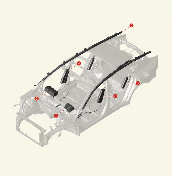
1. Driver Airbag (DAB)
2. Passenger Airbag
(PAB)
3. Driver Side Airbag (SAB)
|
4. Passenger Side Airbag (SAB)
5. Rear Side
Airbag
6. Curtain Airbag (CAB)
|
Description and Operation
|
•
|
The airbag plays a role in protecting the driver by deploying in the event of a severe
collision or
rollover accident.
|
|
•
|
The airbag consists of driver, knee, and passenger airbags deployed in frontal collisions and
side and
curtain airbags deployed in side collisions or rollover accidents.
|
On Vehicle Inspection
| 1.
|
The driver airbag can be more quickly diagnosed for problems with the KDS (Refer to "DTC
guide").
| (1)
|
Self diagnosis : Inspect the Diagnostic Trouble Code (DTC) with the KDS.
(Refer to DTC guide when fault code is found)
|
| (2)
|
Data analysis : Checking the system input/output data state
(Data Analysis → Airbag)
|
|
Refer to the KDS screen for operating conditions and details.
|
|
Clock Spring Description and Operation
The clock spring is a device that transmits the operation signal generated from the sensors installed on the
front and side of the vehicle to the inflator (gas generator) of the airbag via the internal cable. It also
transmits the steering wheel remote control switch and horn operation signals to the system via the internal
cable.
|
If the airbag is deployed due to an accident, the clock spring cannot be repaired or reused
because there
is a possibility of damage to the clock spring due to heat and impact caused by the explosion of
the airbag
inflator (gas generating device). Be sure to replace with a new one.
|
Clock Spring Troubleshooting
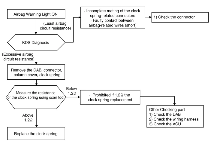
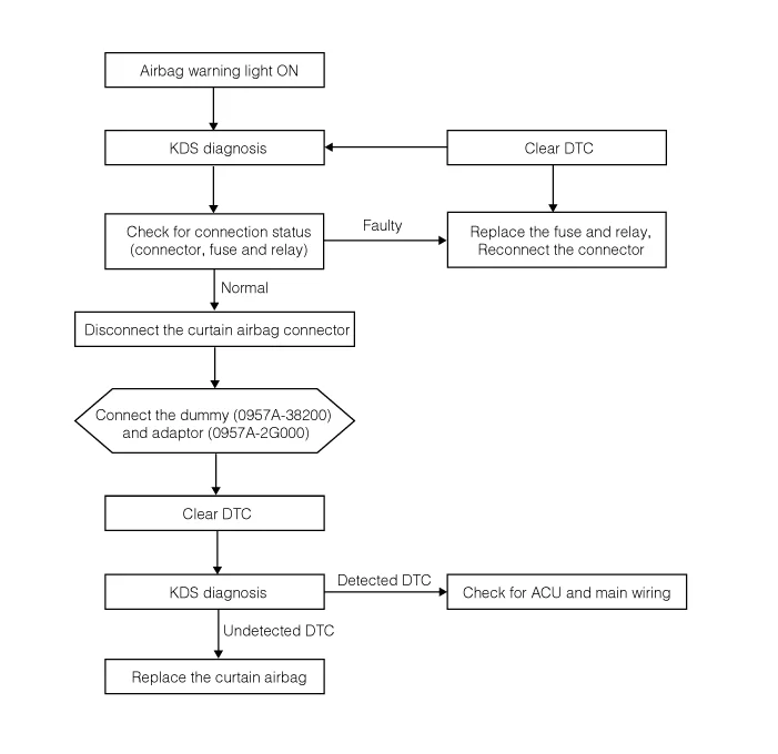
Airbag Warning Light On
| The Clock Spring Repair Procedure |
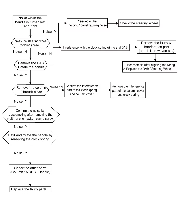
Noise
| The Clock Spring Repair Procedure |
Clock Spring Replacement
|
The clock spring cannot be replaced individually due to included in the multifunction switch.
If
necessary, replace the multifunction switch.
|
| 1.
|
Replace the multifunction switch.
(Refer to Body - "Multifunction Switch")
|
Clock Spring Adjustment
| Clock Spring Neutral Position Setting |
| 1.
|
Set the clock spring in a neutral position
|
Curtain Airbag (CAB) On Vehicle Inspection
| 1.
|
The center side airbag can be more quickly diagnosed for problems with the KDS (Refer to "DTC
guide").
| (1)
|
Self diagnosis : Inspect the Diagnostic Trouble Code (DTC) with the KDS.
(Refer to DTC guide when fault code is found)
|
|
Refer to the KDS screen for operating conditions and details.
|
|
Curtain Airbag (CAB) Troubleshooting
|
Direct measuring the resistance of the airbag is very dangerous as it can cause the airbag
deployment.
|
Curtain Airbag (CAB) Removal and Installation
| 1.
|
Disconnect the battery negative (-) terminal.
|
After disconnecting the battery negative ( - ) terminal, wait at least 3
minutes and 30 seconds.
|
|
| 2.
|
Remove the roof trim assembly.
(Refer to Body - "Roof Trim Assembly")
|
| 3.
|
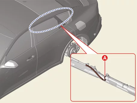
Disconnect the Curtain Airbag (CAB) connector (A).
|
| 4.
|
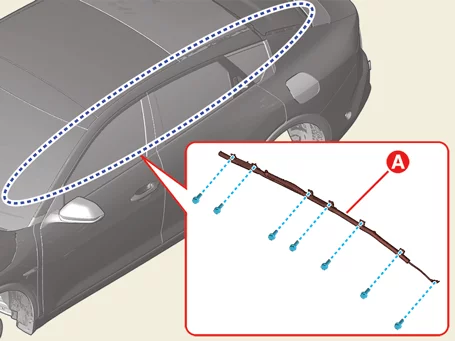
Remove the CAB (A) after removing the bolts.
|
Tightening torque :
7.8 - 11.8 N·m (0.8 - 1.2 kgf·m, 5.8 - 8.7 lb·ft)
|
|
| 1.
|
Install in the reverse order of removal.
|
•
|
Be sure to keep the torque specifications presented in shop
manuals. Otherwise, it could
lead to the malfunction of airbag system.
|
|
•
|
Be careful not to twist when the curtain airbag installing. The
curtain airbag may not
deploy normally if twisted.
|
|
•
|
Use the color of sentence and line on a module to identify
curtain airbag.
|
|
–
|
Driver's side : Blue label (attached to plastic cover)
|
|
–
|
Passenger's side : Red label (attached to plastic cover)
|
|
|
| 2.
|
Check that the airbag system operates normally.
|
When the IG is on, the airbag warning lamp should turns off after turning on
for 3 - 6 seconds.
|
|
Driver Airbag (DAB) On Vehicle Inspection
| 1.
|
The driver airbag can be more quickly diagnosed for problems with the KDS (Refer to "DTC
guide").
| (1)
|
Self diagnosis : Inspect the Diagnostic Trouble Code (DTC) with the KDS.
(Refer to DTC guide when fault code is found)
|
|
Refer to the KDS screen for operating conditions and details.
|
|
Driver Airbag (DAB) Troubleshooting
|
Direct measuring the resistance of the airbag is very dangerous as it can cause the airbag
deployment.
|
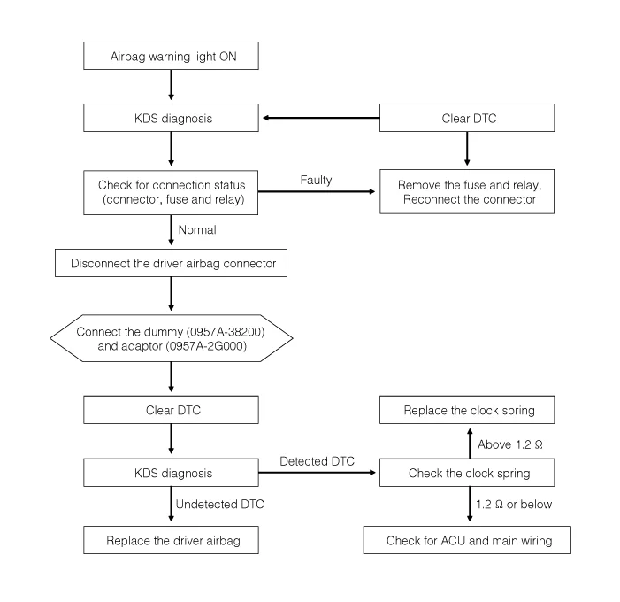
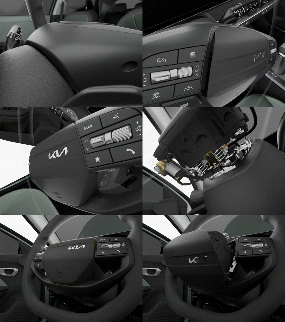
Driver Airbag (DAB) Removal and Installation
Standard
| 1.
|
Disconnect the battery negative (-) terminal.
|
After disconnecting the battery negative ( - ) terminal, wait at least 3
minutes and 30 seconds.
|
|
| 2.
|
Remove the upper steering column shroud panel. [In Cabin Cam
(ICC)
only]
(Refer to Body - "Steering Column Shroud Panel")
|
| 3.
|
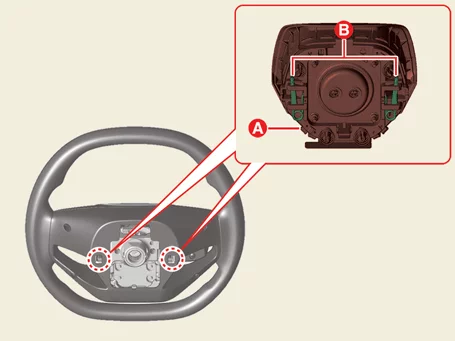
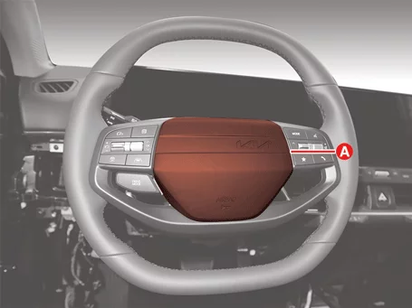
Remove the DAB.
| (1)
|
Separate the DAB (A) after releasing the clips (B).
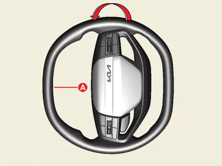
|
When separating the DAB, rotate the steering wheel (A) as shown
below illustration. [Both
side]
|
|
| (2)
|
Align the steering wheel straight.
|
| (3)
|
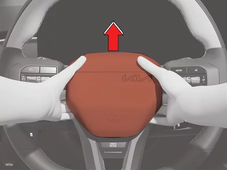
Remove the DAB (A).
|
Hold the top of the DAB cover from the front and lift it
towards the driver's direction.
|
|
|
| 4.
|
Disconnect the connectors (A, B).
A : DAB connector
B : Horn connector
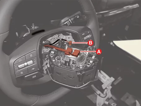
|
Option
| 1.
|
Disconnect the battery negative (-) terminal.
|
After disconnecting the battery negative ( - ) terminal, wait at least 3
minutes and 30 seconds.
|
|
| 2.
|
Release the DAB clips (A) by pushing it in the direction of the arrow.
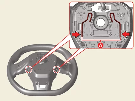
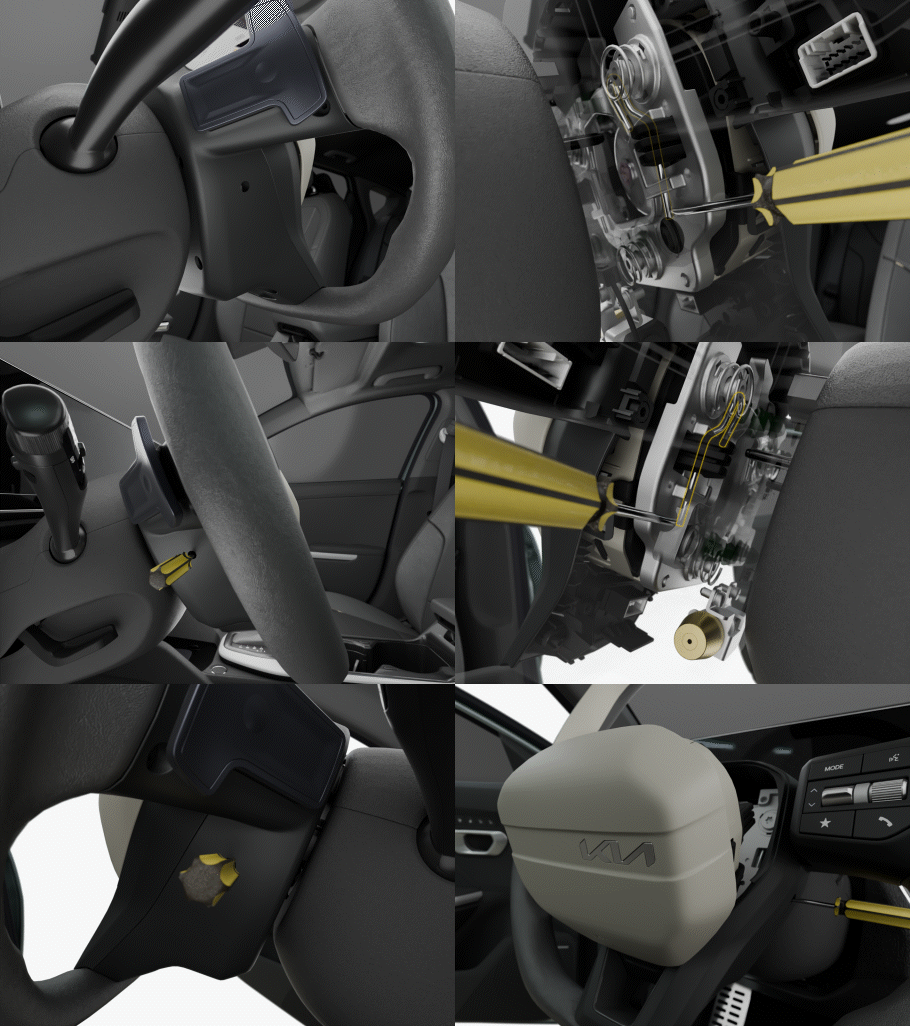
|
| 3.
|
Remove the DAB (A).
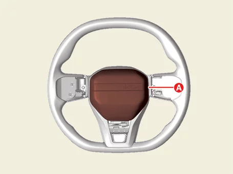
|
| 4.
|
Disconnect the DAB connectors (A).
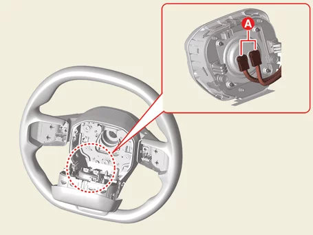
|
| 1.
|
Install in the reverse order of removal.
|
•
|
When assembling the driver airbag to the wheel, make sure that
the airbag wire is not
caught in the wheel's internal structure.
|
|
•
|
Assemble the airbag wire while pressing it toward the center of
the driver airbag.
|
|
|
| 2.
|
Check the airbag system operate normally.
|
When the IG is on, the airbag warning lamp should turns off after turning on
for 3 - 6 seconds.
|
|
Passenger Airbag (PAB) On Vehicle Inspection
| 1.
|
The passenger airbag can be more quickly diagnosed for problems with the KDS (Refer to "DTC
guide").
| (1)
|
Self diagnosis : Inspect the Diagnostic Trouble Code (DTC) with the KDS.
(Refer to DTC guide when fault code is found)
|
|
Refer to the KDS screen for operating conditions and details.
|
|
Passenger Airbag (PAB) Troubleshooting
|
Direct measuring the resistance of the airbag is very dangerous as it can cause the airbag
deployment.
|
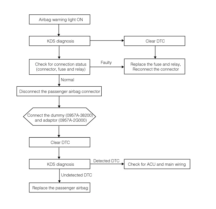
Passenger Airbag (PAB) Removal and Installation
Passenger Airbag (PAB)
| 1.
|
Remove the crash pad assembly.
(Refer to Body - "Crash Pad Assembly")
|
| 2.
|
Remove the PAB (A) after removing the bolts.
|
Tightening torque :
3.9 - 5.9 N·m (0.4 - 0.6 kgf·m, 2.9 - 4.3 lb·ft, 34.7 - 52.1 lb·in)
|
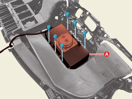
|
| 1.
|
Install in the reverse order of removal.
|
Be sure to keep the torque specifications presented in shop manuals. Otherwise,
it could lead to
the malfunction of airbag system.
|
|
| 2.
|
Check that the airbag system operates normally.
|
When the IG is on, the airbag warning lamp should turns off after turning on
for 3 - 6 seconds.
|
|
Side Airbag (SAB) On Vehicle Inspection
| 1.
|
The side airbag can be more quickly diagnosed for problems with the KDS (Refer to "DTC guide").
| (1)
|
Self diagnosis : Inspect the Diagnostic Trouble Code (DTC) with the KDS.
(Refer to DTC guide when fault code is found)
|
|
Refer to the KDS screen for operating conditions and details.
|
|
Side Airbag (SAB) Troubleshooting
|
Direct measuring the resistance of the airbag is very dangerous as it can cause the airbag
deployment.
|
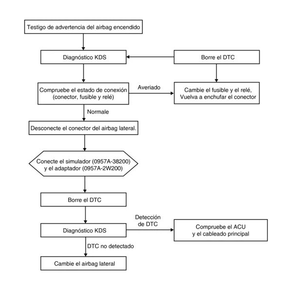
Side Airbag (SAB) Removal and Installation
|
When replacing the airbag due to deployment of the airbag, replace the seat back assembly.
|
|
The indication below represents the location of a clip or fastener.

|
Front Side Airbag (SAB)
| 1.
|
Remove the front seat back frame assembly.
(Refer to Body - "Front Seat Frame Assembly")
|
| 2.
|
Remove the SAB (A) after removing the nuts.
|
Tightening torque:
5.9 - 7.8 N·m (0.6 - 0.8 kgf·m, 4.3 - 5.8 lb·ft, 52.1 - 69.4 lb·in)
|
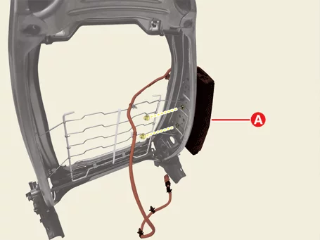
|
Rear Side Airbag (SAB)
| 1.
|
Remove the side seat back assembly.
(Refer to Body - "Rear Seat Assembly")
|
| 2.
|
Separate the SAB connector wiring (A) by pulling it in the direction of the arrow.
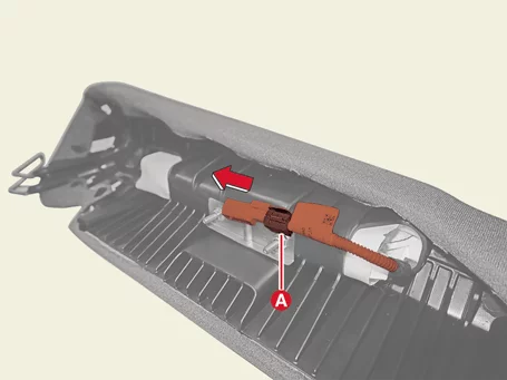
|
| 3.
|
Remove the SAB bracket (A) after removing the nuts.
|
Tightening torque:
5.9 - 7.8 N·m (0.6 - 0.8 kgf·m, 4.3 - 5.8 lb·ft, 52.1 - 69.4 lb·in)
|
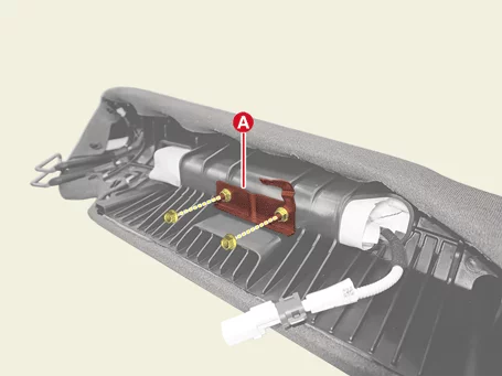
|
| 4.
|
Remove the side seat back cover assembly (A) from the frame.
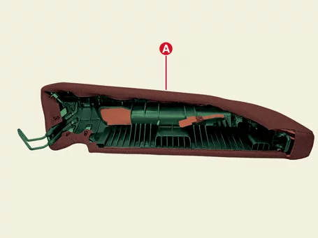
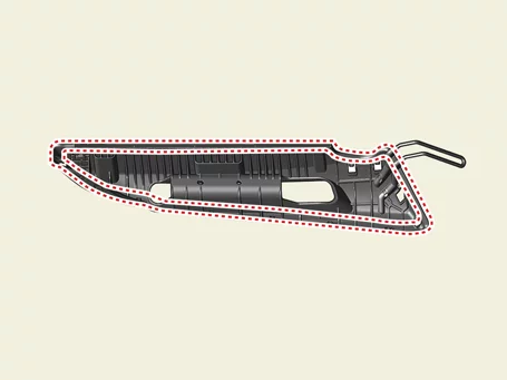
|
| 5.
|
Remove the side seat back cover (A).
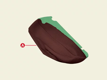
|
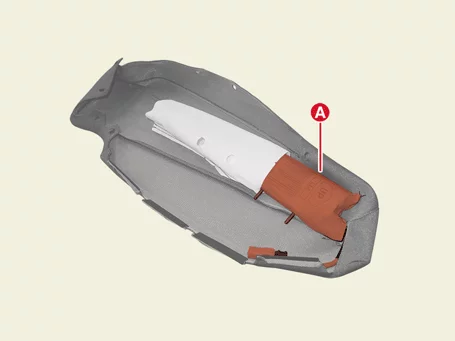
| 6.
|
Remove the SAB (A).
|
| 1.
|
Disconnect the battery negative (-) terminal.
|
After disconnecting the battery negative ( - ) terminal, wait at least 3
minutes and 30 seconds.
|
|
| 2.
|
Remove the rear seat back assembly.
(Refer to Body - "Rear Seat Assembly")
|
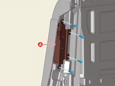
| 3.
|
Remove the SAB & bracket (A) after removing the bolts.
|
Tightening torque:
7.8 - 11.8 N·m (0.8 - 1.2 kgf·m, 5.8 - 8.7 lb·ft)
|
|
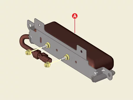
| 4.
|
Remove the SAB (A) after removing the nuts.
|
Tightening torque:
5.9 - 7.8 N·m (0.6 - 0.8 kgf·m, 4.3 - 5.8 lb·ft, 52.1 - 69.4 lb·in)
|
|
| 1.
|
Install in the reverse order of removal.
|
•
|
Be sure to keep the torque specifications presented in shop
manuals. Otherwise, it could
lead to the malfunction of airbag system.
|
|
•
|
Since improper installation of the seat back cover will prevent
the normal deployment of
the side airbags, make sure that the seat back cover is properly
installed.
|
|
|
| 2.
|
Check that the airbag system operates normally.
|
When the IG is on, the airbag warning lamp should turns off after turning on
for 3 - 6 seconds.
|
|
Other information:
Kia K4 (CL4) 2025-2026 Service Manual: Consumer assistance for the Kia K4 (U.S. only)
Every new Kia K4 model is backed by a comprehensive Roadside Assistance program. This coverage begins on the vehicle's in-service date—defined as the date the vehicle is delivered to its first retail buyer or otherwise put into use—and remains valid for a period of 60 months or 60,000 miles, whichever occurs first. Please consult the Kia Warranty and Consumer Information Manual specifically applicable to your Kia K4 model year for a complete breakdown of terms, conditions, and specific exclusions.
Kia K4 (CL4) 2025-2026 Service Manual: Wide sunroof:
If your specific vehicle package is configured with the optional premium wide sunroof assembly, you can effortlessly slide open or tilt the glass panel using the multi-stage electronic sunroof switch located conveniently on the overhead console panel.
To protect the battery state of charge, you can only actuate the panoramic or wide sunroof tracking system when the ENGINE START/STOP button is placed in the active ON or START power mode positions.