
Kia K4: Automatic Transaxle System / Automatic Transaxle
Kia K4 (CL4) 2025-2026 Service Manual / Automatic Transaxle System / Automatic Transaxle
Contents:
Components and Components Location
| Component |
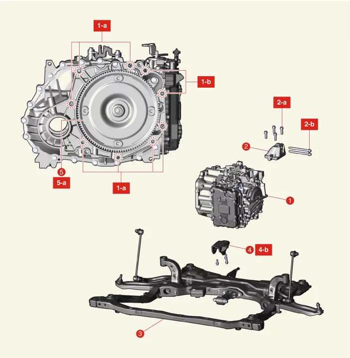
| 1. Automatic Transaxle
Assmembly 1-a. 42.2 - 53.9 N·m (4.3 - 5.5 kgf·m, 31.1 - 39.8 lb·ft) 1-b. 49.0 - 63.7 N·m (5.0 - 6.5 kgf·m, 36.2 - 47.0 lb·ft) 2. Automatic Transaxle Support Bracket 2-a. 58.8 - 78.5 N·m (6.0 - 8.0 kgf·m, 43.4 - 57.9 lb·ft) 2-b. 88.3 - 107.9 N·m (9.0 - 11.0 kgf·m, 65.1 - 79.6 lb·ft) |
3. Front
Subframe 4. Roll Rod Support Bracket 4-a. 49.0 - 68.6 N·m (5.0 - 7.0 kgf·m, 36.2 - 50.6 lb·ft) 5. Torque Converter Assembly 5-a. 45.1 - 52.0 N·m (4.6 - 5.3 kgf·m, 33.3 - 38.3 lb·ft) |
Removal
| Video Guide |
|


Video: Automatic Transaxle Removal
| Special Service Tool |
| Tool Name / Number |
Illustration |
Description |
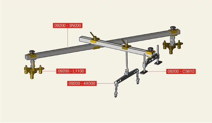
| Engine support fixture (bar) 09200 - 3N000 |
|
Used for holding engine assembly when removing / installing automatic
transaxle ※ Refer to the engine support fixture assembly below |
| Engine support fixture (front supporter) 09200 - C3610 |
|
Used for holding engine assembly when removing / installing automatic
transaxle ※ Refer to the engine support fixture assembly below |
|
Engine support fixture (rear supporter) 09200 - L1100 |
|
Used for holding engine assembly when removing / installing automatic transaxle ※ Refer to the engine support fixture assembly below |
|
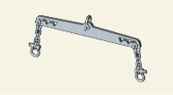
Engine fixture (adapter) 09200 - 4X000 |
|
Used for holding engine assembly when removing / installing automatic transaxle ※ Refer to the engine support fixture assembly below |
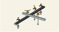
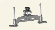
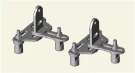
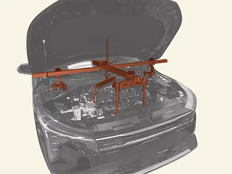
※ Engine support fixture assembly
| Removal |
| 1. | Remove the air cleaner assembly. (Refer to Engine Mechanical System - "Air Cleaner") |
| 2. | Remove the battery and battery tray. (Refer to Engine Electrical System - "Battery") |
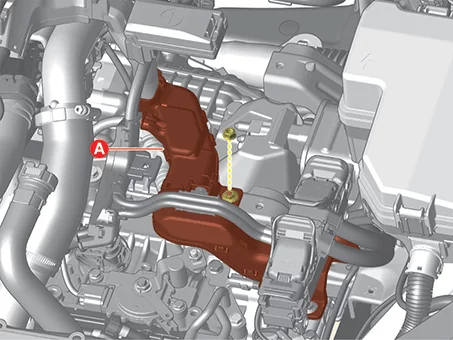
| 3. |
Separate the main wiring protector (A) from the body frame.
|
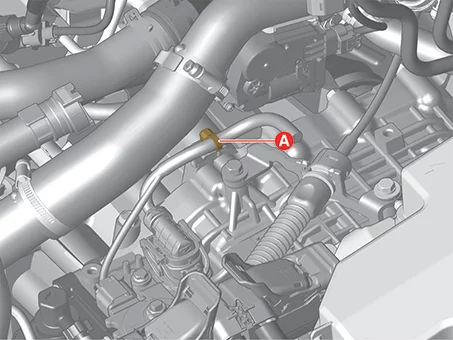
| 4. |
Remove the wiring fixing clip (A).
|
| 5. |
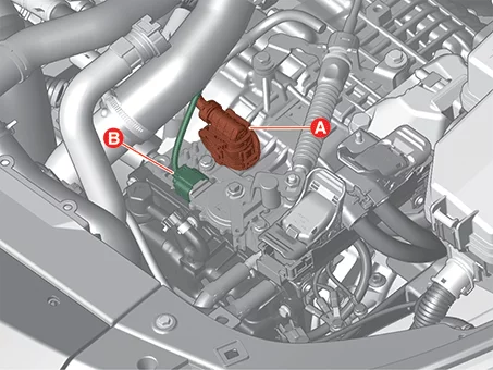
Disconnect the connectors (A, B).
|
| 6. |
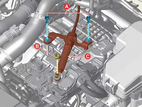
Remove the shift cable (C) after removing the bolts (A) and nut (B).
|
| 7. |
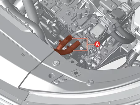
Separate the ATF cooler hoses (A) after releasing the clamp.
|
| 8. |
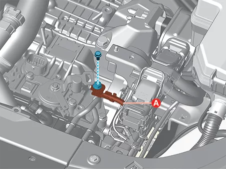
Remove the ground cable (A) by removing the bolt.
|
| 9. |
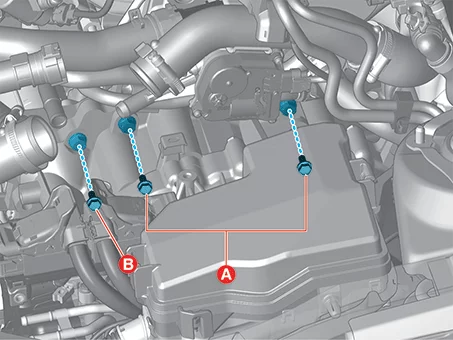
Remove the automatic transaxle upper bolts (A) and starter upper bolt (B).
|
| 10. |
Assemble the engine support fixture in the engine room.
|
| 11. | Remove the engine room under cover. (Refer to Engine Mechanical System - "Engine Room Under Cover") |
| 12. |
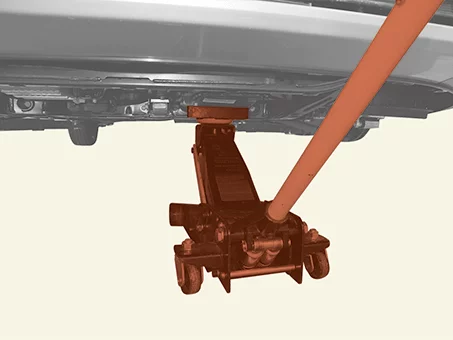
Support the automatic transaxle with a jack.
|
| 13. |
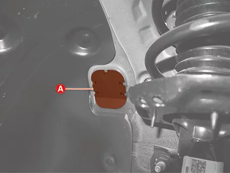
Remove the cover (A).
|
| 14. |
Remove the automatic transaxle mounting bracket bolts (A).
|
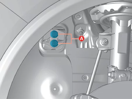
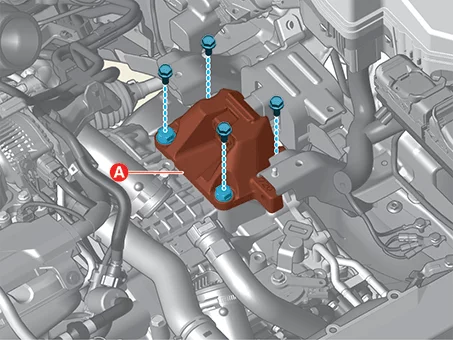
| 15. |
Remove the automatic transaxle support bracket (A) after removing the bolts.
|
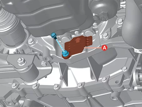
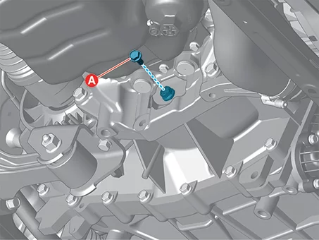
| 16. |
Remove the acoustic shield cover (A) after removing the bolt.
|
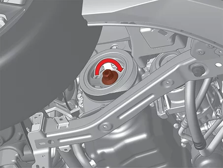
| 17. |
Remove the torque converter bolts (A - 4pcs) by rotating the crankshaft in clockwise direction.
|
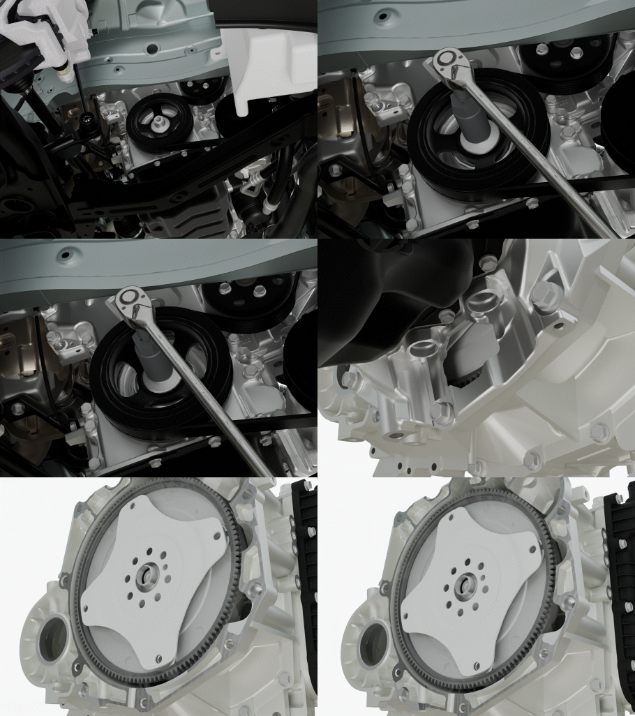
| 18. | Remove the front subframe. (Refer to Suspension System - "Front Subframe") |
| 19. |
Remove the front drive shaft (A).
|
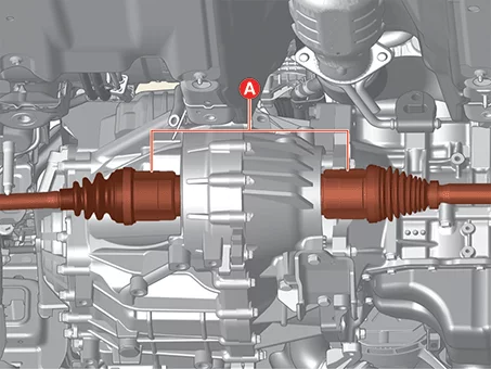
| 20. |
Remove the roll rod support bracket (A) by removing the bolts.
|
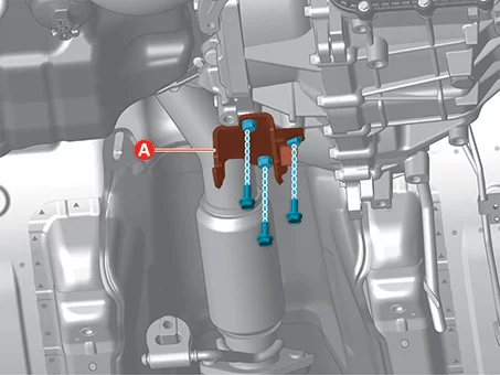
| 21. | Support the automatic transaxle securely using a jack. |
| 22. |
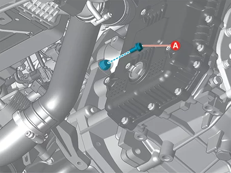
Remove the starter lower bolt (A).
|
| 23. |
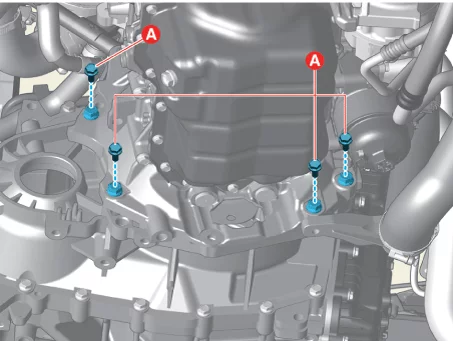
Remove the automatic transaxle lower bolts (A).
|
| 24. |
Remove the automatic transaxle by lowering the jack slowly after separating the automatic
transaxle from
the engine.
|
Installation ➤


Other information:
Kia K4 (CL4) 2025-2026 Service Manual: Tightening Torque
Tightening Torque Alignment Alignment Item N·m kgf·m lb·ft lb·in Tie rod end and rod nut 49.Kia K4 (CL4) 2025-2026 Service Manual: Rear occupant alert (ROA) system
The advanced Rear Occupant Alert (ROA) system integrated into your vehicle is a vital driver assistance feature configured to monitor the rear passenger cabin. This sub-system actively reduces the risk of a child, infant, vulnerable passenger, or family pet being inadvertently left behind in the vehicle when the driver exits. Environmental Sensor Optimization Protocol: To ensure the underlying ultrasonic interior sensors function with maximum accuracy, make sure that all side passenger windows and the sunroof assembly are completely closed whenever the ROA framework is operational.

Copyright © 2026 Kia K4 Manuals � 0.0088