|
•
|
This video was created using 3D graphics to help understand the vehicle
maintenance manual.
|
|
•
|
There may be some differences from actual vehicles.
|
|
•
|
The location and repair procedures of the parts may vary depending on vehicle
model, model year,
region, and specifications.
|
|
•
|
Check the KDS Guide for detailed information on how to use the KDS.
|
|
•
|
Check the manual for detailed maintenance procedures.
|
|
•
|
Unauthorized reproduction, distribution, or sharing of this video is
prohibited.
|
|
Transaxle Service Procedure by Condition (Used / Remanufactured / New)
(Click to play)

Video: Transaxle Service Procedure by Condition
(Used /
Remanufactured / New)
Automatic Transaxle Installation
#1 (Click to play)
Video: Automatic Transaxle Installation #1
#2 (Click to play)
Video: Automatic Transaxle Installation #2
Tool Name / Number
|
Illustration
|
Description
|
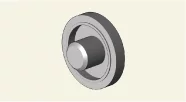
Oil seal installer
09452 - 26100
|
|
Used for transaxle case and housing oil seal installation
(Used with the handle)
|
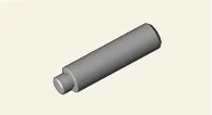
Handle
09231 - H1100
|
|
Used for transaxle case and housing oil seal installation
(Used with the oil seal installer)
|
| 1.
|
When ATF leakage occurs due to the damage of the differential oil seal, replace the seal with a
new one.
|
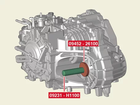
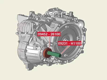
When installing a new oil seal, use the handle (09231 - H1100) and specified
oil seal installer.
Automatic transaxle case and housing : Oil seal installer (09452 - 26100)
|
|
| 2.
|
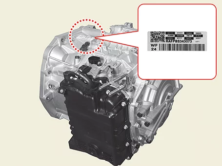
Check and note the oil pressure characteristics of the automatic transaxle.
|
It is difficult to check after installing the automatic transaxle, so make a
note before
installing it.
|
|
| 3.
|
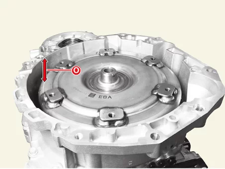
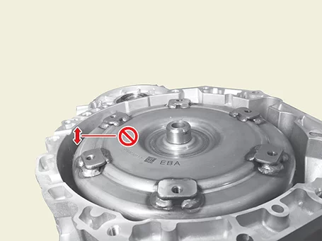
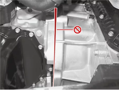
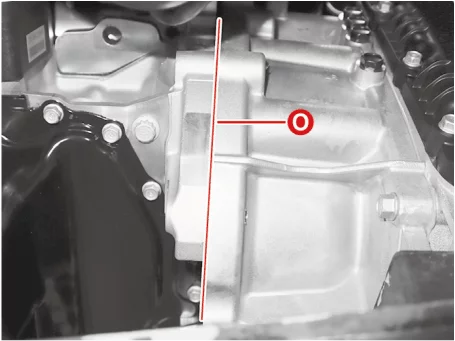
Check that the torque converter is correctly assembled.
| (1)
|
Check the depth from the face of the converter housing to the torque converter
with the torque
converter is facing up.
[Correct assembly condition]
[Incorrect assembly condition]
|
| (2)
|
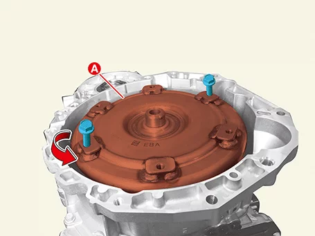
When the torque converter protrudes, secure the automatic transaxle mounting
bolt to the torque
converter (A) and rotate it to seat it on the oil pump key.
|
•
|
A gap is generated between the engine block and
the torque converter housing when
the engine and the automatic transaxle are
combined in a state where the torque
converter is not properly assembled. If the gap
occurs, remove the automatic
transaxle and reassemble the torque converter to
fit the oil pump key part.
Torque
converter incorrect assembly
Torque
converter correct assembly
|
|
•
|
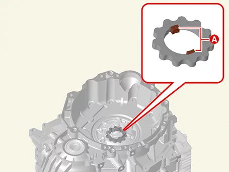
If the fixing bolt is forcibly tightened while
there is a gap, the oil pump gear
key (A) will be damaged. In this case, loosen
the fastening bolts and replace the
automatic transaxle assembly.
|
|
|
|
| 4.
|
Install the automatic transaxle by slowly raising the jack.
|
Be careful not to damage other nearby systems or parts when installing the
automatic transaxle
assembly.
|
|
| 5.
|
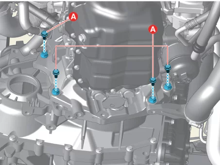
Install the automatic transaxle lower bolts (A).
|
Tightening torque :
42.2 - 53.9 N·m (4.3 - 5.5 kgf·m, 31.1 - 39.8 lb·ft)
|
|
| 6.
|
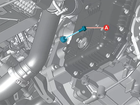
Install the starter lower bolt (A).
|
Tightening torque :
49.0 - 63.7 N·m (5.0 - 6.5 kgf·m, 36.2 - 47 lb·ft)
|
|
| 7.
|
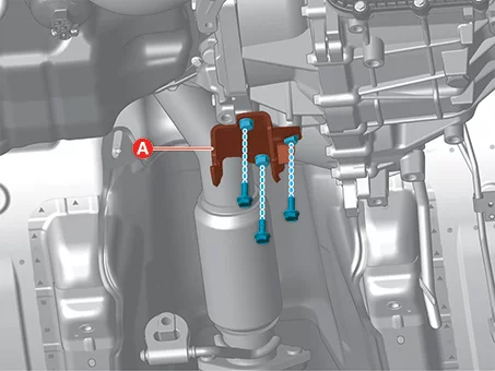
Install the roll rod support bracket (A).
|
Tightening torque :
49.0 - 68.6 N·m (5.0 - 7.0 kgf·m, 36.2 - 50.6 lb·ft)
|
|
| 8.
|
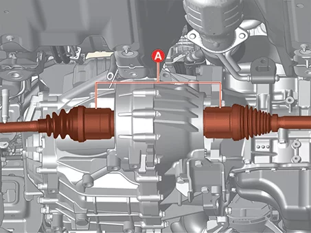
Install the front drive shaft (A).
|
| 9.
|
Install the front subframe.
(Refer to Suspension System - "Front Subframe")
|
| 10.
|
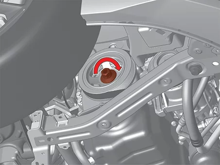
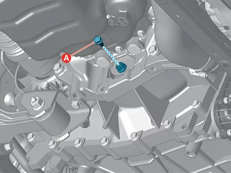
Install the torque converter bolts (A - 4pcs) by rotating the crankshaft in clockwise
direction.
|
Tightening torque :
45.1 - 52.0 N·m (4.6 - 5.3 kgf·m, 33.3 - 38.3 lb·ft)
|
|
•
|
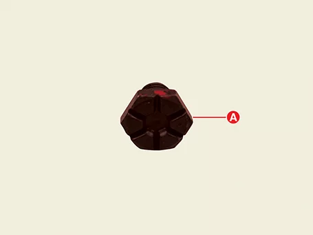
Lubricate the threads before tightening the torque converter
bolts (A).
|
|
•
|
Pre-tighten the all torque converter bolts (4pcs), then
securely tighten to the specified
torque.
|
|
|
| 11.
|
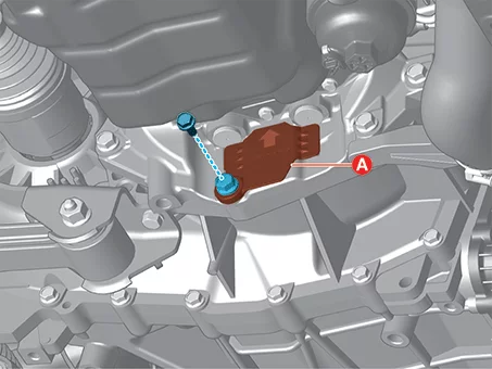
Install the acoustic shield cover (A).
|
Tightening torque :
42.2 - 53.9 N·m (4.3 - 5.5 kgf·m, 31.1 - 39.8 lb·ft)
|
|
| 12.
|
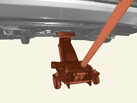
Support the automatic transaxle with a jack.
|
| 13.
|
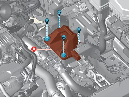
Install the automatic transaxle support bracket (A).
|
Tightening torque :
58.8 - 78.5 N·m (6.0 - 8.0 kgf·m, 43.4 - 57.9 lb·ft)
|
|
| 14.
|
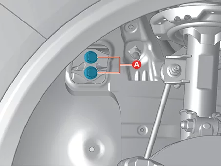
Install the automatic transaxle mounting bracket bolts (A).
|
Tightening torque :
88.3 - 107.9 N·m (9.0 - 11.0 kgf·m, 65.1 - 79.6 lb·ft)
|
|
When tightening bolts, first tighten the lower bolt and then the upper bolt.
|
|
| 15.
|
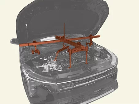
Remove the engine support fixture.
|
| 16.
|
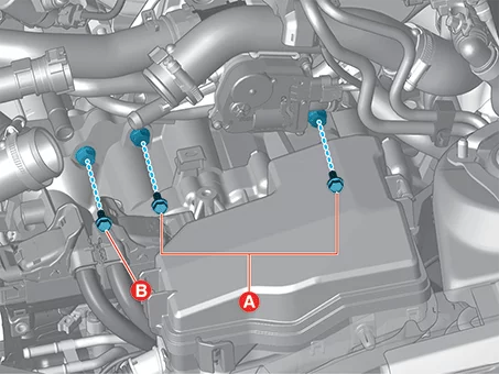
Install the automatic transaxle upper bolts (A) and starter bolt (B).
|
Tightening torque :
(A) 42.2 - 53.9 N·m (4.3 - 5.5 kgf·m, 31.1 - 39.8 lb·ft)
(B) 49.0 - 63.7 N·m (5.0 - 6.5 kgf·m, 36.2 - 47.0 lb·ft)
|
|
| 17.
|
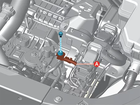
Install the ground cable (A).
|
Tightening torque :
26.5 - 32.4 N·m (2.7 - 3.3 kgf·m, 19.5 - 23.9 lb·ft)
|
|
| 18.
|
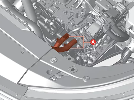
Install the ATF cooler hoses (A).
|
| 19.
|
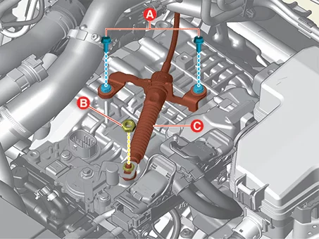
Tighten the bolts (A) and nut (B) after installing the shift cable (C).
|
Tightening torque :
(A) 14.7 - 21.6 N·m (1.5 - 2.2 kgf·m, 10.8 - 15.9 lb·ft)
(B) 9.8 - 13.7 N·m (1.0 - 1.4 kgf·m, 7.2 - 10.1 lb·ft)
|
|
| 20.
|
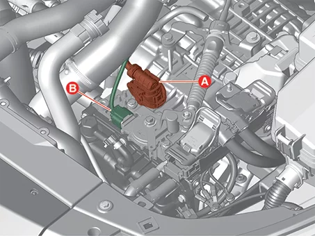
Connect the connectors (A, B).
|
A : Main connector
B : Position switch connector
|
|
| 21.
|
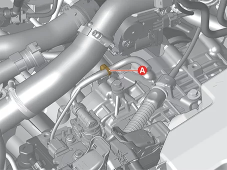
Install the wiring fixing clip (A).
|
| 22.
|
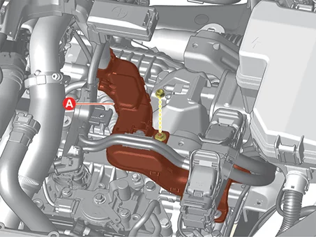
Install the main wiring protector (A).
|
Tightening torque :
4.9 - 7.8 N·m (0.5 - 0.8 kgf·m, 3.6 - 5.8 lb·ft)
|
|
| 23.
|
Install the battery and battery tray.
(Refer to Engine Electrical System - "Battery")
|
| 24.
|
Install the air cleaner assembly.
(Refer to Engine Mechanical System - "Air Cleaner")
|
| 25.
|
Install the engine room under cover.
(Refer to Engine Mechanical System - "Engine Room Under
Cover")
|
| 26.
|
Perform the following task depending on whether the automatic transaxle is replaced.
When reinstalling the automatic transaxle
| (1)
|
If ATF leakage occurs while removing the transmission, perform ATF
replenishment and level check
procedures.
(Refer to Hydraulic System - "Fluid")
|
| (2)
|
Check the alignment.
(Refer to Suspension System -
"Alignment")
|
| (3)
|
Clear the diagnostic trouble codes (DTC) using the KDS.
|
DTC cannot be deleted by disconnecting the battery terminals.
|
|
When installing a new automatic transaxle
| (1)
|
New automatic transaxle is already filled with the specified amount of ATF. For
this reason, it
is not necessary to refill and check the ATF.
It is not necessary to refill and check the ATF. However, the
remaining ATF in the ATF
cooler has to be drained.
|
1) |
Connect the air gun to the ATF cooler hose.
|
|
2) |
Use a beaker to receive ATF that is discharged
through the opposite hose by
injecting air.
|
|
|
| (2)
|
Clear the diagnostic trouble codes (DTC) using the KDS.
|
DTC cannot be deleted by disconnecting the battery terminals.
|
|
| (3)
|
Perform in the order below using the KDS.
(S/W Management → Automatic Transaxle → Resetting Auto T/A Values)
|
Refer to the KDS screen for operating conditions and details.
|
|
| (4)
|
Perform in the order below using the KDS.
(S/W Management → Automatic Transaxle → Oil-pressure Characteristics Input)
|
Refer to the KDS screen for operating conditions and details.
|
|
| (5)
|
Perform TCM learning procedure.
(Refer to Automatic Transaxle Control System -
"Adjustment")
|
| (6)
|
Check the alignment.
(Refer to Suspension System -
"Alignment")
|
When replacing with a remanufactured automatic transaxle
| (1)
|
Remanufactured automatic transaxle is not filled with specified quantity of
ATF. For that reason,
it is necessary to refill and check the ATF.
|
| (2)
|
Check the ATF level after refilling the automatic transaxle with fluid.
(Refer to Hydraulic System - "Fluid")
|
| (3)
|
Clear the diagnostic trouble codes (DTC) using the KDS.
|
DTC cannot be deleted by disconnecting the battery terminals.
|
|
| (4)
|
Perform in the order below using the KDS.
(S/W Management → Automatic Transaxle → Resetting Auto T/A Values)
|
Refer to the KDS screen for operating conditions and details.
|
|
| (5)
|
Perform in the order below using the KDS.
(S/W Management → Automatic Transaxle → Oil-pressure Characteristics Input)
|
Refer to the KDS screen for operating conditions and details.
|
|
| (6)
|
Perform TCM learning procedure.
(Refer to Automatic Transaxle Control System -
"Adjustment")
|
| (7)
|
Check the alignment.
(Refer to Suspension System -
"Alignment")
|
|
Other information:
Kia K4 (CL4) 2025-2026 Service Manual: Tire Pressure Monitoring System (TPMS)
The Kia K4 is equipped with a sophisticated Tire Pressure Monitoring System (TPMS) that continuously monitors the inflation pressure of each tire and transmits this data to the instrument cluster for your convenience.
Low tire pressure or TPMS malfunction indicator light.
Kia K4 (CL4) 2025-2026 Service Manual: Lane Keeping Assist (LKA)
When operating your Kia K4 at speeds above a certain threshold, the Lane Keeping Assist (LKA) system actively monitors road lane markings and edges. Designed to enhance your driving experience, Lane Keeping Assist can provide proactive steering assistance to help prevent your Kia K4 from unintentionally drifting out of its lane. Furthermore, the system is engineered to provide an alert if it detects that the vehicle is departing from its lane without the driver engaging the turn signal.