Contents:
Inspection
| Operation and Leakage Check |
Component
|
Procedure
|
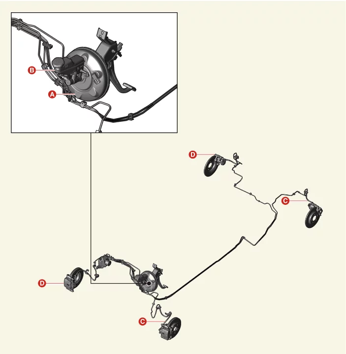
Brake booster (A)
|
Check brake operation by applying the brakes during a test drive. If the
brakes do not
work properly, check the brake booster. Replace the brake booster as an assembly if it does not work
properly
or if there are signs of leakage.
|
Piston cup and pressure cup inspection (B)
|
Check brake operation by applying the brakes. Look for damage or signs of
fluid
leakage. Replace the master cylinder as an assembly if the pedal does not work properly or if there
is damage
or signs of fluid leakage.•
Check for a difference in brake pedal stroke between quick and slow
brake
applications. Replace the master cylinder if there is a difference in pedal stroke.
|
Brake hose (C)
|
Look for damage or signs of fluid leakage. Replace the brake hose with a new
one if it
is damaged or leaking.
|
Caliper piston seal and piston boots (D)
|
Check brake operation by applying the brakes and look for damage or signs of fluid leakage. If the
pedal does
not work properly, the brakes drag, or there is damage or signs of fluid leakage, disassemble and
inspect the
brake caliper. Replace the boots and seals with new ones whenever the brake caliper is
disassembled.
|
| Abnormal Disc Vibration (Judder Inspection) |
Symptom
|
Description
|
Inspection
|
Vehicle body vibration
|
Vibration in the crash pad (dash), steering column, steering wheel, and/or vehicle body when braking
|
Check DTV (Disc Thickness Variation) or Disc Run-out
|
Brake pedal pulsation
|
The brake pedal pulsates, and sometimes the steering wheel oscillates (wobble) when braking.
|
| 1.
|
Driving Test
Drive the car at 30 MPH without brake and change the gear to neutral and release the
accelerator pedal at
the same time, then let the vehicle drift for 500 meters (0.3 miles), check there is any
vibration, and
locate where the highest vibration and noise are loacted.
| (1)
|
Occurring after high-speed driving/braking (Cannot perform the drive test) →
Check disc
deformation.
|
–
|
Disc overheating → Rapid cooling due to car
washing or rain → Disc thermal
deformation
|
|
–
|
Use of non-genuine brake pads with high
coefficient of friction → Disc
overheating → Disc thermal deformation
|
|
–
|
Unaligned wheel balance → Steering wheel
oscillates when driving at high speed.
|
|
|
| (2)
|
Occurring after high / low - speed driving (Can perform the drive test) → Check
Disc or Pad
deformation.
|
If symptoms are mild, check the disc run-out and determine if a
disc replacement is
necessary.
|
|
|
| 2.
|
Disc Inpsection
| (1)
|
Disc thermal deformation and hot spots → Replace disc.
|
| (2)
|
Check DTV (Disc Thickness Variation) → If the disc run-out value exceeds limit,
replace the disc.
(Refer to Front Brake Disc - "On Vehicle
Inspection")
(Refer to Rear Brake Disc - "On Vehicle
Inspection")
|
| (3)
|
If no disc deformation → Check pad for damage
|
|
| 3.
|
Check pads for damage
|
Service limit :
[15", 16" Disc]
Front : 2.0 mm (0.07 in.) or less
[14", 15" Disc]
Rear : 7.0 mm (0.27 in.) or less
|
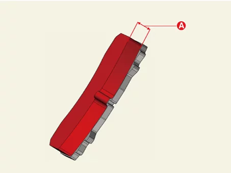
| (1)
|
If the thickness of the brake pads exceeds the service limit or there is a
crack or signs of
heat, replace the brake pads.
|
|
Brake Booster Components and Components Location
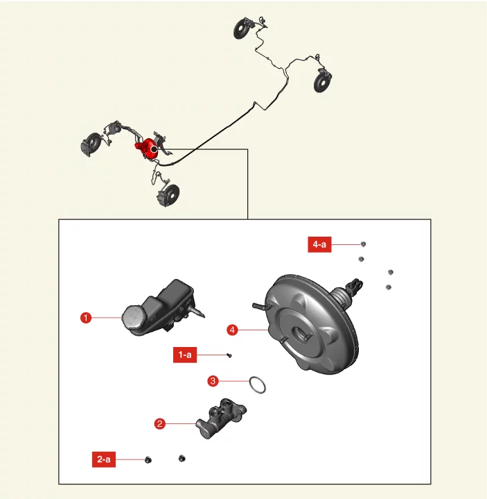
1. Reservoir Tank
1-a. 1.0 - 1.5 N·m (0.10
- 0.15
kgf·m, 0.7 - 1.1 lb·ft, 8.8 - 13.3 lb·in)
2. Master Cylinder Assembly
2-a. 9.8 - 15.7 N·m
(1.0 - 1.6
kgf·m, 7.2 - 11.6 lb·ft)
|
3. Master Cylinder O-Ring
4. Brake Booster
Assembly
4-a. 16.7 - 25.5 N·m (1.7 - 2.6 kgf·m, 12.3 - 18.8 lb·ft)
|
Brake Booster Adjustment
| Brake Booster Operation Test |
| 1.
|
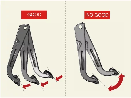
Run the engine for 1 - 2 minutes and stop, when the brake pedal is pressed down several times,
it is
normal if the brake pedal stroke gradually drcreases.
If the brake pedal stroke is constant, the brake bootster is defective.
|
| 2.
|
Press the brake pedal with the engine stationary, and then start the engine. if the brake pedal
moves
downwards it is normal and abnormal if the brake pedal does not move.
|
| 3.
|
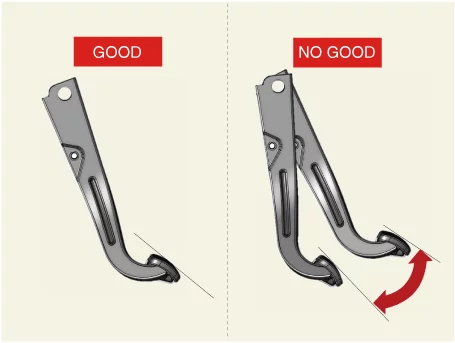
Depress the brake pedal and stop the engine while the engine is running.
If the brake pedal does not move, it is normal but if the brake pedal rises up, the brake
booster is
defective.
|
If the brake booster meets all 3 steps above, the brake booster is OK. if even
one step fails,
check the check valve, vacuum hose, and brake booster.
|
|
Brake Booster Removal and Installation
G 1.6 T-GDI GAMMA II
| 1.
|
Remove the battery tray.
G 1.6 T-GDI GAMMA II (Refer to Engine Electrical System -
"Battery")
|
| 2.
|
Drain the coolant.
G 1.6 T-GDI GAMMA II (Refer to Engine Mechanical System -
"Coolant")
|
| 3.
|
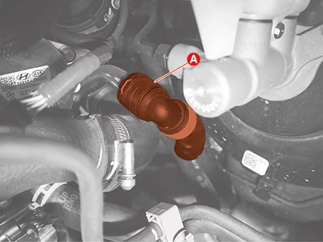
Disconnect the heater hose (A) after releasing the quick connector.
|
| 4.
|
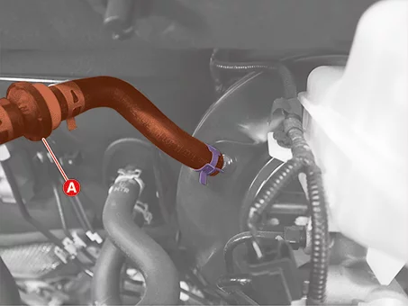
Disconnect the brake vacuum hose (A) after releasing the clamp.
|
| 5.
|
Remove the brake master cylinder.
(Refer to Brake System - "Brake Master Cylinder")
|
| 6.
|
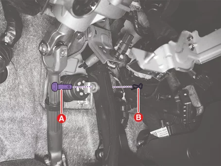
Remove the brake pedal arm mounting clevis pin (A) and snap pin (B).
|
| 7.
|
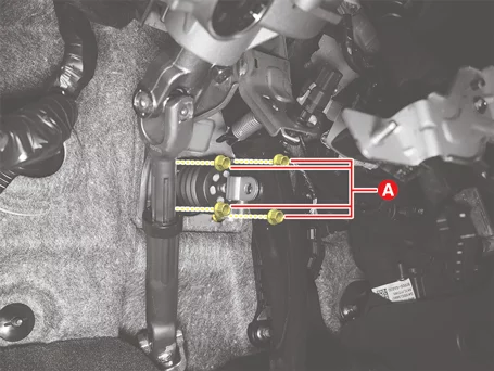
Remove the brake booster nuts (A).
|
Tightening torque :
16.7 - 25.5 N·m (1.7 - 2.6 kgf·m, 12.3 - 18.8 lb·ft)
|
|
| 8.
|
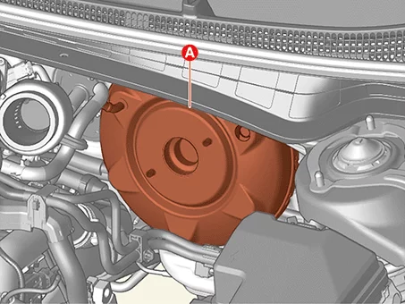
Remove the brake booster (A).
|
G 2.0 MPI NU(ATKINSON)
| 1.
|
Remove the battery tray.
G 2.0 MPI NU(ATKINSON) (Refer to Engine Electrical System -
"Battery")
|
| 2.
|
Disconnect the brake vacuum hose (A) after releasing the clamp.
|
| 3.
|
Remove the brake master cylinder.
(Refer to Brake System - "Brake Master Cylinder")
|
| 4.
|
Remove the brake pedal arm mounting clevis pin (A) and snap pin (B).
|
| 5.
|
Remove the brake booster nuts (A).
|
Tightening torque :
16.7 - 25.5 N·m (1.7 - 2.6 kgf·m, 12.3 - 18.8 lb·ft)
|
|
| 6.
|
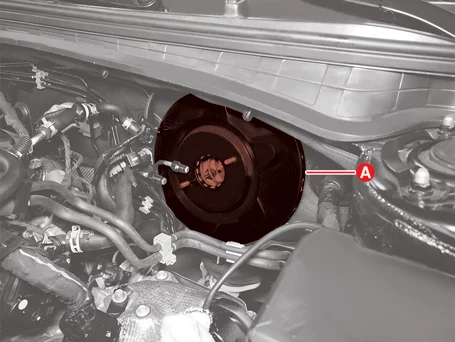
Remove the brake booster (A).
|
| 1.
|
Install in the reverse order of removal.
|
•
|
Install to the specified torque.
|
|
•
|
Be careful not to twist the brake vacuum hose when installing.
|
|
•
|
Apply the grease when installing the brake pedal arm clevis pin
(Grease type : GREASE
PDLV-1)
|
|
•
|
Be careful not to change the mounting position of the clevis
pin and snap pin.
|
|
|
To minimize damage to the thread and brake member assembly during installation,
tighten all nuts
with hands and then tighten them to the tightening torque values in the order
shown below.
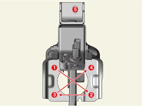
|
|
| 2.
|
Perform the brake bleeding procedures.
(Refer to Brake System - "Brake Bleeding")
|
| 3.
|
Check the brake fluid leakage and pedal operating condition.
|
Brake Booster Inspection
| 1.
|
Check the check valve inside the vacuum hose.
|
Do not disassemble the check valve from the vacuum hose.
|
|
| 2.
|
Check the boots for damage.
|
Brake Line Components and Components Location
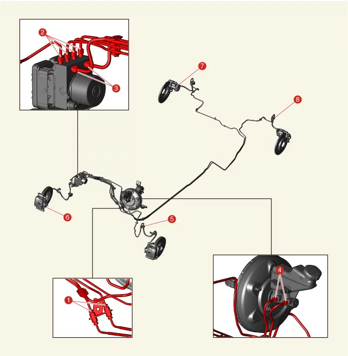
1. Brake Tube Flare Nut (2 Way Bracket) 12.7 -
16.7
N·m (1.3 - 1.7 kgf·m, 9.4 - 12.3 lb·ft)
2. Brake Tube Flare Nut (ESC Unit to Each Caliper) 12.7
- 16.7 N·m
(1.3 - 1.7 kgf·m, 9.4 - 12.3 lb·ft)
3. Brake Tube Flare Nut (ESC Unit to Master Cylinder) 12.7 -
16.7 N·m
(1.3 - 1.7 kgf·m, 9.4 - 12.3 lb·ft)
4. Brake Tube Flare Nut (Master Cylinder to ESC Unit) 18.6 -
22.6 N·m
(1.9 - 2.3 kgf·m, 13.7 - 16.6 lb·ft)
5. Brake Tube Flare Nut (FL Brake Hose) 12.7 - 16.7 N·m
(1.3 - 1.7
kgf·m, 9.4 - 12.3 lb·ft)
|
6. Brake Hose to Caliper (FR) 24.5 - 29.4 N·m
(2.5 -
3.0 kgf·m, 18.1 - 21.7 lb·ft)
7. Brake Hose to Caliper (RR) 24.5 - 29.4 N·m (2.5 - 3.0 kgf·m,
18.1 - 21.7
lb·ft)
8. Brake Tube Flare Nut (RL Brake Hose) 12.7 - 16.7 N·m (1.3 - 1.7 kgf·m, 9.4 - 12.3
lb·ft)
|
Brake Line Removal and Installation
|
Be careful not to spill brake fluid onto the vehicle or body. If brake fluid leaks, remove with
a clean
cloth as soon as possible.
|
| 1.
|
Remove the front wheel and tires.
(Refer to Suspension System - "Wheel")
|
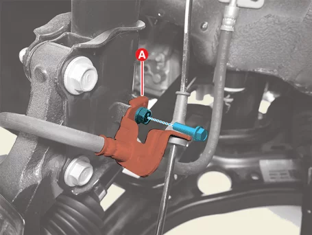
| 2.
|
Remove the front brake hose bracket (A) after removing the bolt.
|
Tightening torque:
8.8 - 13.7 N·m (0.9 - 1.4 kgf·m, 6.5 - 10.1 lb·ft)
|
|
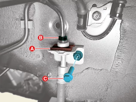
| 3.
|
Separate the front brake hose from the body.
| (1)
|
Remove the clip (A), and loosen the flare nut (B).
|
Tightening torque :
12.7 - 16.7 N·m (1.3 - 1.7 kgf·m, 9.4 - 12.3 lb·ft)
|
|
| (2)
|
Separate the front brake hose after removing the bolt (C).
|
Tightening torque :
8.8 - 13.7 N·m (0.9 - 1.4 kgf·m, 6.5 - 10.1 lb·ft)
|
|
|
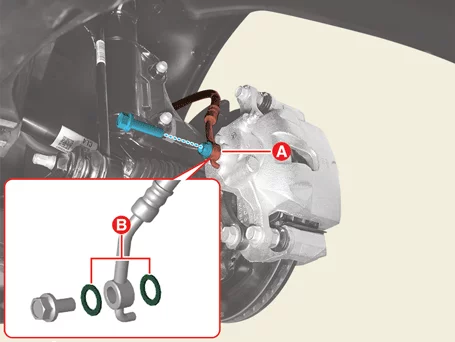
| 4.
|
Remove the front brake hose assembly (A) after removing the bolt.
|
Tightening torque :
24.5 - 29.4 N·m (2.5 - 3.0 kgf·m, 18.1 - 21.7 lb·ft)
|
|
Do not reuse the washer (B).
|
|
| 1.
|
Remove the rear wheel and tires.
(Refer to Suspension System - "Wheel")
|
| 2.
|
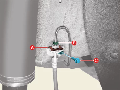
Separate the rear brake hose from the body.
| (1)
|
Remove the clip (A), and loosen the flare nut (B).
|
Tightening torque :
12.7 - 16.7 N·m (1.3 - 1.7 kgf·m, 9.4 - 12.3 lb·ft)
|
|
| (2)
|
Separate the rear brake hose after removing the bolt (C).
|
Tightening torque :
8.8 - 13.7 N·m (0.9 - 1.4 kgf·m, 6.5 - 10.1 lb·ft)
|
|
|
| 3.
|
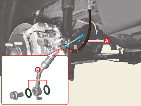
Remove the rear brake hose (A) after removing the bolt.
|
Tightening torque:
24.5 - 29.4 N·m (2.5 - 3.0 kgf·m, 18.1 - 21.7 lb·ft)
|
|
Do not reuse the washer (B).
|
|
| 1.
|
Install in the reverse order of removal.
|
Install to the specified torque.
|
|
| 2.
|
Perform the brake air bleeding procedure.
(Refer to Brake System - "Brake Bleeding")
|
•
|
If air does not occur after the first brake bleed operation,
the 'HCU Air Bleeding Mode'
procedure may be omitted.
|
|
•
|
But if the ESC unit or reservoir tank is replaced, do not omit
the 'HCU Air bleeding
mode' procedure.
|
|
|
Brake Line Inspection
| 1.
|
Check the brake tube and hose for crack or corrosion.
|
| 2.
|
Check the tube flare nuts for damage.
|
Brake Master Cylinder Components and Components Location
1. Reservoir Tank
1-a. 1.0 - 1.5 N·m (0.10
- 0.15
kgf·m, 0.7 - 1.1 lb·ft, 8.8 - 13.3 lb·in)
2. Master Cylinder Assembly
2-a. 9.8 - 15.7 N·m
(1.0 - 1.6
kgf·m, 7.2 - 11.6 lb·ft)
|
3. Master Cylinder O-Ring
4. Brake Booster
Assembly
4-a. 16.7 - 25.5 N·m (1.7 - 2.6 kgf·m, 12.3 - 18.8 lb·ft)
|
Brake Master Cylinder Removal and Installation
G 1.6 T-GDI GAMMA II
| 1.
|
Remove the air cleaner assembly.
G 1.6 T-GDI GAMMA II (Refer to Engine Mechanical System - "Air
Cleaner")
|
| 2.
|
Remove the battery.
G 1.6 T-GDI GAMMA II (Refer to Engine Electrical System -
"Battery")
|
| 3.
|
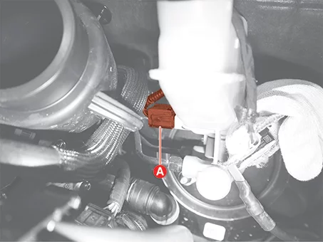
Disconnect the brake fluid level sensor connector (A).
|
| 4.
|
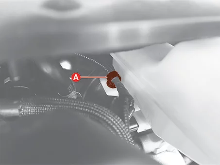
Separate the brake fluid level sensor wire clip (A).
|
| 5.
|
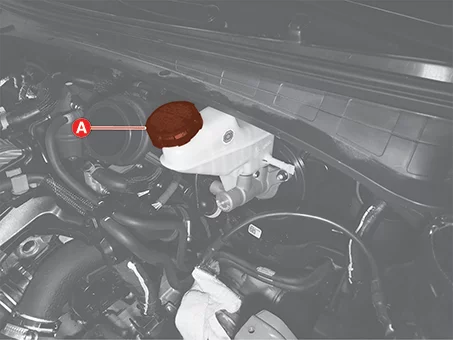
Remove the reservoir cap (A) and then clean brake fluid from the reservoir tank using a
suitable tool.
|
Be careful not to spill brake fluid onto the vehicle or body. If brake fluid
leaks, remove with a
clean cloth as soon as possible.
|
|
Be careful not to get brake fulid on the body or vehicle. Wipe with a clean
cloth immediately if
there is brake fluid on it.
|
|
| 6.
|
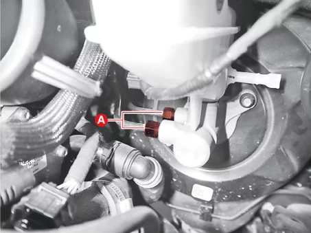
Disconnect the brake tube after removing the flare nuts (A).
|
Tightening torque :
18.6 - 22.6 N·m (1.9 - 2.3 kgf·m, 13.7 - 16.6 lb·ft)
|
|
| 7.
|
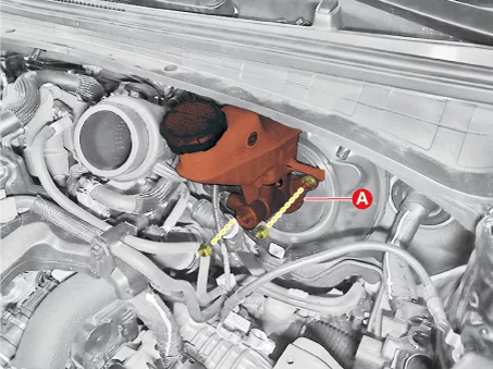
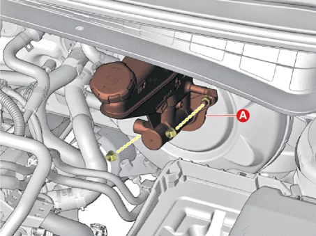
Remove the master cylinder assembly (A) after removing the nuts.
|
Tightening torque :
9.8 - 15.7 N·m (1.0 - 1.6 kgf·m, 7.2 - 11.6 lb·ft)
|
|
G 2.0 MPI NU(ATKINSON)
| 1.
|
Remove the battery.
G 2.0 MPI NU(ATKINSON) (Refer to Engine Electrical System -
"Battery")
|
| 2.
|
Disconnect the brake fluid level sensor connector (A).
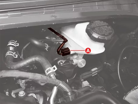
|
| 3.
|
Separate the brake fluid level sensor wire clip (A).
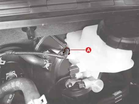
|
| 4.
|
Remove the reservoir cap (A) and then clean brake fluid from the reservoir tank using a
suitable tool.
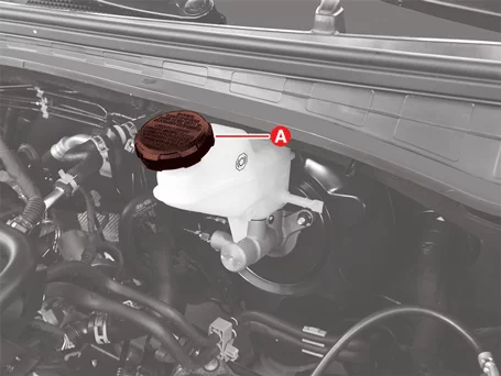
|
Be careful not to spill brake fluid onto the vehicle or body. If brake fluid
leaks, remove with a
clean cloth as soon as possible.
|
|
Be careful not to get brake fulid on the body or vehicle. Wipe with a clean
cloth immediately if
there is brake fluid on it.
|
|
| 5.
|
Disconnect the brake tube after removing the flare nuts (A).
|
Tightening torque :
18.6 - 22.6 N·m (1.9 - 2.3 kgf·m, 13.7 - 16.6 lb·ft)
|
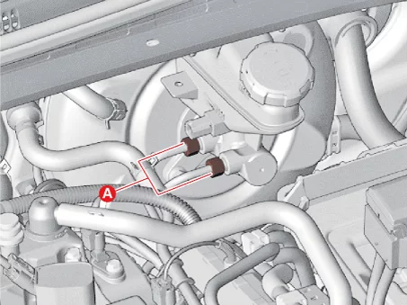
|
| 6.
|
Remove the master cylinder assembly (A) after removing the nuts.
|
Tightening torque :
9.8 - 15.7 N·m (1.0 - 1.6 kgf·m, 7.2 - 11.6 lb·ft)
|
|
| 1.
|
Install in the reverse order of removal.
|
Install to the specified torque.
|
|
| 2.
|
Perform in the brake bleeding procedure.
(Refer to Brake System - "Brake Bleeding")
|
| 3.
|
Check the brake fluid leakage and pedal operating condition.
|
Brake Pedal Components and Components Location
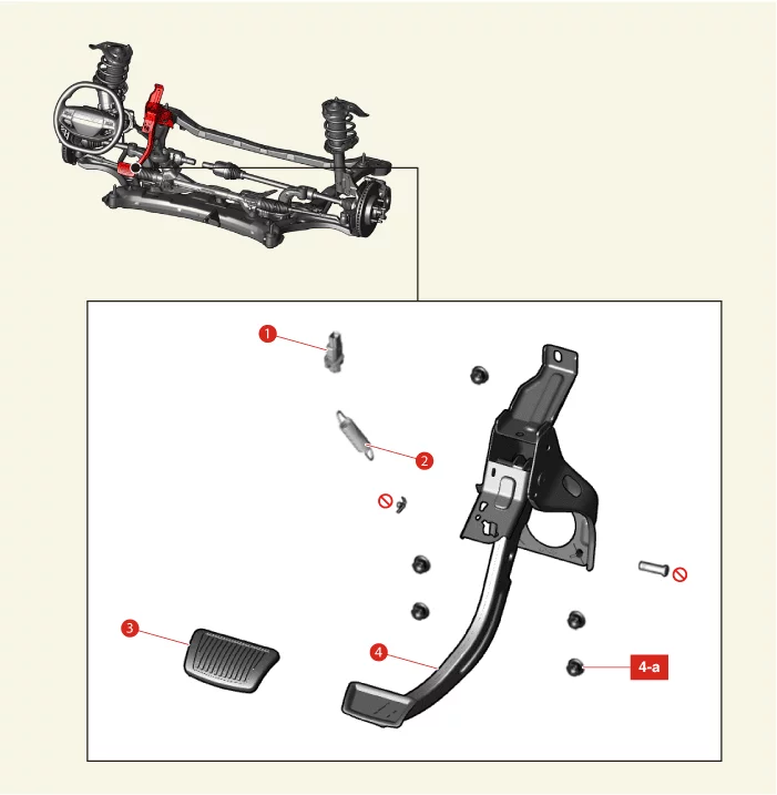
1. Stop Lamp Switch
2. Return Spring
3.
Brake
Pedal Pad
|
4. Brake Pedal Member Assembly
4-a. 16.7 -
25.5 N·m
(1.7 - 2.6 kgf·m, 12.3 - 18.8 lb·ft)
|
Brake Pedal Removal and Installation
| 1.
|
Disconnect the battery negative ( - ) terminal.
|
| 2.
|
Remove the central communication unit (CCU).
(Refer to Body - Central Communication Unit (CCU))
|
| 3.
|
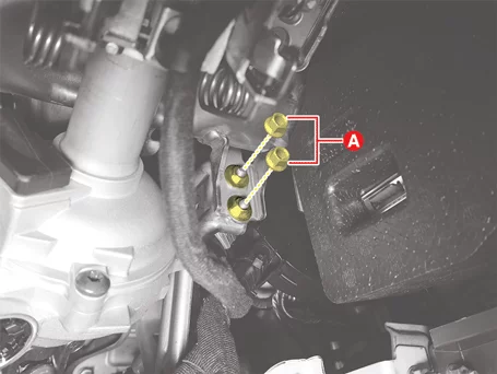
Remove the pedal support bracket after removing the nuts (A).
|
Tightening torque :
6.9 - 10.8 N·m (0.7 - 1.1 kgf·m, 5.1 - 8.0 lb·ft, 60.8 - 95.5 lb·in )
|
|
| 4.
|
Disconnect the stop lamp switch connector (A).
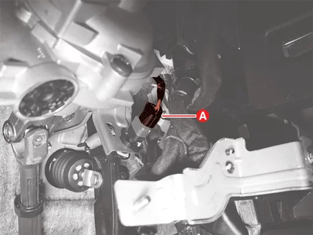
|
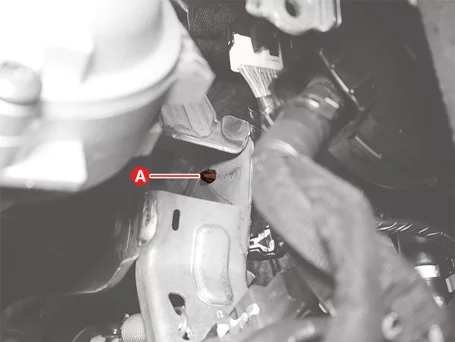
| 5.
|
Remove the stop lamp switch connector wiring clip (A).
|
| 6.
|
Remove the brake pedal arm mounting clevis pin (A) and snap pin (B).
|
| 7.
|
Remove the brake booster nuts (A).
|
Tightening torque :
16.7 - 25.5 N·m (1.7 - 2.6 kgf·m, 12.3 - 18.8 lb·ft)
|
|
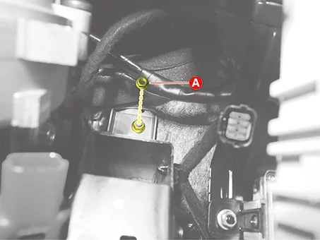
| 8.
|
Remove the brake pedal assembly after removing the nut (A).
|
Tightening torque :
16.7 - 25.5 N·m (1.7 - 2.6 kgf·m, 12.3 - 18.8 lb·ft)
|
|
| 1.
|
Install in the reverse order of removal.
|
•
|
Apply the grease when installing the brake pedal arm clevis pin
(Grease type : GREASE
PDLV-1)
|
|
•
|
Be careful not to change the mounting position of the clevis
pin and split pin.
|
|
•
|
Install to the specified torque.
|
|
|
To minimize damage to the thread and brake member assembly during installation,
tighten all nuts
with hands and then tighten them to the tightening torque values in the order
shown below.
|
|
| 2.
|
Check the brake pedal operating normally after installation.
|
Brake Pedal Disassembly and Reassembly
| 1.
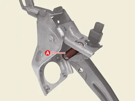
|
Remove the brake pedal return spring (A).
|
| 2.
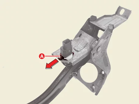
|
Pull the locking plate (A) in the direction of the arrow.
|
| 3.
|
Remove the stop lamp switch (A) by turning counterclockwise.
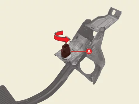
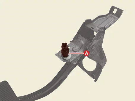
|
| 1.
|
Reassemble in the reverse order of disassembly.
|
•
|
Install to the specified torque.
|
|
•
|
Apply grease when reassembling the brake return spring. (Grease
Type : GREASE PDLV-1)
|
|
•
|
Check the stop lamp switch clearance (A) and reinstall the stop
lamp switch if the
clearance exceeds the limit.
|
Stop lamp
switch clearance (A) : 1.0 - 2.0
mm (0.03 - 0.07 in.)
|
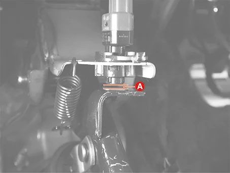
|
|
|
Brake Pad Removal
Front Brake Pad
| 1.
|
Remove the front wheel and tires.
(Refer to Suspension System - "Wheel")
|
| 2.
|
Separate the front brake caliper body (A) after removing the bolt.
|
Tightening torque :
21.6 - 31.4 N·m (2.2 - 3.2 kgf·m, 15.9 - 23.1 lb·ft)
|
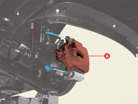
|
Secure the separated front brake caliper body (A) using a suitable tool such as
the hook (B).
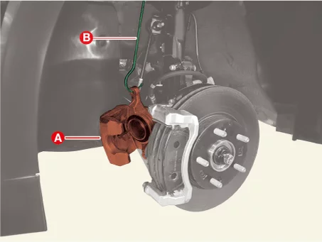
|
|
| 3.
|
Remove the brake pads (A).
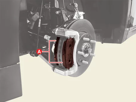
|
| 4.
|
Remove the brake pad liners (A).
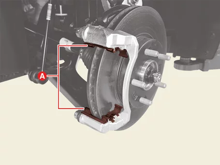
|
•
|
When replacing the brake pad, replace all brake pad parts (pad,
liner, pad inner shim)
together.
|
|
•
|
Note the direction when replacing the pad liner and inner pad
inner shim.
|
|
•
|
Make sure that the pad liner fits securely when replacing the
pad liner.
|
|
•
|
If the pad liner is deformed or not properly installed, poor
brake performance / drag /
noise can occur.
|
|
•
|
Be careful not to deform the return spring (A) of the pad liner
(retraction part).
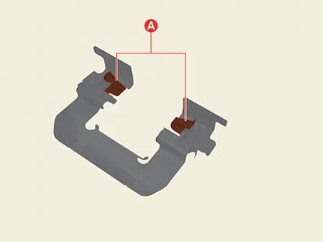
|
|
|
Rear Brake Pad
| 1.
|
Perform in the order below with the KDS.
(S/W Management → ABSESP - Braking Control → Brake Pad Change Mode)
|
Refer to the KDS screen for operating conditions and details
|
|
| 2.
|
Disconnect the battery negative ( - ) terminal.
|
| 3.
|
Remove the rear wheel and tires.
(Refer to Suspension System - "Wheel")
|
| 4.
|
Disconnect the EPB connector (A).
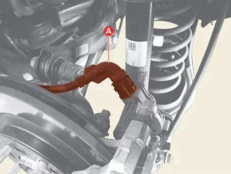
|
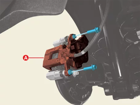
| 5.
|
Separate the rear brake caliper body (A) after removing the bolts.
|
Tightening torque :
21.6 - 31.4 N·m (2.2 - 3.2 kgf·m, 15.9 - 23.1 lb·ft)
|
|
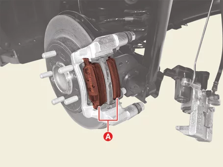
| 6.
|
Remove the brake pads (A).
|
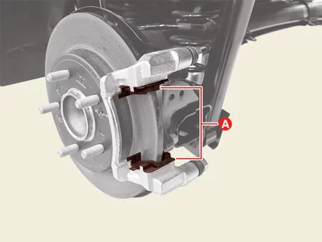
| 7.
|
Remove the brake pad liners (A).
|
•
|
When replacing the brake pad, replace all brake pad parts (pad,
liner, pad inner shim)
together.
|
|
•
|
Note the direction when replacing the pad liner and inner pad
inner shim.
|
|
•
|
Make sure that the pad liner fits securely when replacing the
pad liner.
|
|
•
|
If the pad liner is deformed or not properly installed, the
poor brake performance / drag
/ noise can occur.
|
|
•
|
Be careful not to deform the return spring (A) of the pad liner
(retraction part).
|
|
|
Brake Pad Inspection
| 1.
|
Check brake pad thickness (A). If the thickness is thinner than the limit, replace the brake
pads.
|
Front brake pad thickness
[15", 16" Disc]
Standard : 11.0 mm (0.43 in.)
Service Limit : 2.0 mm (0.07 in.)
|
|
Rear brake pad thickness
[14", 15" Disc]
Standard : 15.0 mm (0.59 in.)
Service Limit : 7.0 mm (0.27 in.)
|
|
| 2.
|
Check that grease is applied to sliding contact points and check the pad and backing metal for
damage.
|
Brake Pad Installation
Tool Name / Number
|
Illustration
|
Description
|
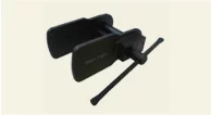
Piston expander
09581 - 11000
|
|
Spreading the front brake caliper piston.
|
Front Brake Pad
| 1.
|
Install in the reverse order of removal.
|
•
|
Check that grease is applied to sliding contact points and
check the pad and backing
metal for damage.
|
|
•
|
Install to the specified torque.
|
|
•
|
Observe the following precautions when installing the inner
brake pads. Incorrect
installation may cause noise or degrade brake performance.
- Make sure that the inner brake pad wear indicator (A) is
facing up on the brake
caliper.
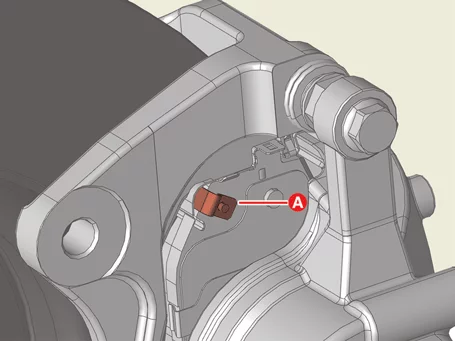
- Make sure that the inner brake pad L (LH caliper) or R (RH
caliper) marks are facing up
on the brake caliper.
|
|
•
|
Be careful not to damage the piston when pressing it.
|
|
•
|
Be careful not to touch the piston when installing the caliper
body to the torque member.
|
|
•
|
Press the brake piston using SST (09581 - 11000) when
installing the caliper body.
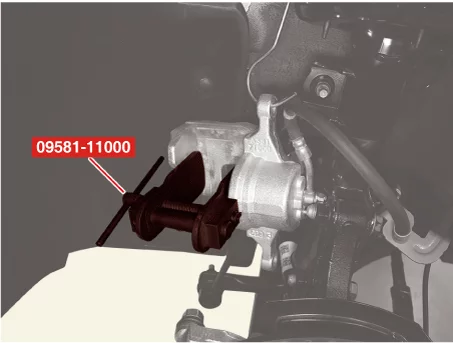
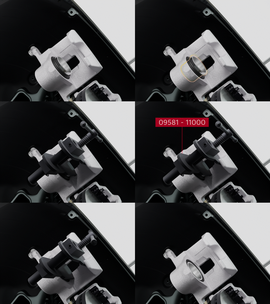
|
|
|
| 2.
|
Depress the brake pedal several times to ensure that the brake pads are correctly positioned,
then check
operation.
|
Rear Brake Pad
| 1.
|
Install in the reverse order of removal.
|
•
|
Check that grease is applied to sliding contact points and
check the pad and backing
metal for damage.
|
|
•
|
Install to the specified torque.
|
|
•
|
Observe the following precautions when installing the inner
brake pads. Incorrect
installation may cause noise or degrade brake performance.
- Make sure that the inner brake pad wear indicator (A) is
facing up on the brake
caliper.
- Make sure that the inner brake pad L (LH caliper) or R (RH
caliper) marks are facing up
on the brake caliper.
|
|
•
|
Be careful not to touch the piston when installing the caliper
body to the torque member.
|
|
•
|
When installing the caliper body, use an suitable tool such as
pliers (A) to rotate the
piston clockwise to press it in.
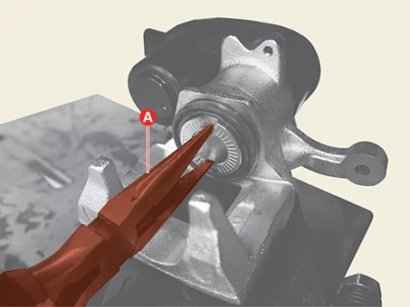
|
|
•
|
Before installing the caliper body, check that the position of
the piston groove (A) is
as shown in following picture.
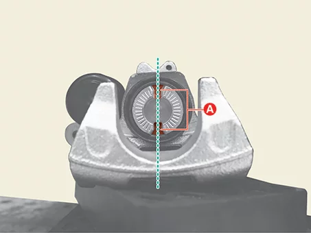
|
|
|
| 2.
|
Perform in the order below with the KDS.
(S/W Management → ABSESP - Braking Control → Brake Pad Change Mode)
|
Refer to the KDS screen for operating conditions and details
|
|
| 3.
|
Apply the parking brake several times and check for normal operation.
|
| 4.
|
Check if the parking brake is operating normally.
|
Brake Pad Replacement
|
•
|
This video was created using 3D graphics to help understand the vehicle
maintenance manual.
|
|
•
|
There may be some differences from actual vehicles.
|
|
•
|
The location and repair procedures of the parts may vary depending on vehicle
model, model year,
region, and specifications.
|
|
•
|
Check the KDS Guide for detailed information on how to use the KDS.
|
|
•
|
Check the manual for detailed maintenance procedures.
|
|
•
|
Unauthorized reproduction, distribution, or sharing of this video is
prohibited.
|
|
Brake Pad Replacement (With KDS, EPB Type)
(Click to play)

Video: Brake Pad Replacement (With KDS, EPB
Type)
Brake Reservoir Tank Components and Components Location
1. Reservoir Tank
1-a. 1.0 - 1.5 N·m (0.10
- 0.15
kgf·m, 0.7 - 1.1 lb·ft, 8.8 - 13.3 lb·in)
2. Master Cylinder Assembly
2-a. 9.8 - 15.7 N·m
(1.0 - 1.6
kgf·m, 7.2 - 11.6 lb·ft)
|
3. Master Cylinder O-Ring
4. Brake Booster
Assembly
4-a. 16.7 - 25.5 N·m (1.7 - 2.6 kgf·m, 12.3 - 18.8 lb·ft)
|
Brake Reservoir Tank Removal and Installation
G 1.6 T-GDI GAMMA II
| 1.
|
Remove the air cleaner assembly.
G 1.6 T-GDI GAMMA II (Refer to Engine Mechanical System - "Air
Cleaner")
|
| 2.
|
Remove the battery.
G 1.6 T-GDI GAMMA II (Refer to Engine Electrical System -
"Battery")
|
| 3.
|
Disconnect the brake fluid level sensor connector (A).
|
| 4.
|
Separate the brake fluid level sensor wire clip (A).
|
| 5.
|
Remove the reservoir cap (A) and then clean brake fluid from the reservoir tank using a
suitable tool.
|
Be careful not to spill brake fluid onto the vehicle or body. If brake fluid
leaks, remove with a
clean cloth as soon as possible.
|
|
Be careful not to get brake fulid on the body or vehicle. Wipe with a clean
cloth immediately if
there is brake fluid on it.
|
|
| 6.
|
Remove the brake reservoir tank (A) after removing the screw.
|
Tightening torque :
1.0 - 1.5 N·m (0.10 - 0.15 kgf·m, 0.7 - 1.1 lb·ft, 8.8 - 13.3 lb·in)
|
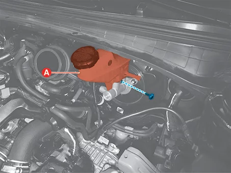
|
G 2.0 MPI NU(ATKINSON)
| 1.
|
Remove the battery.
G 2.0 MPI NU(ATKINSON) (Refer to Engine Electrical System -
"Battery")
|
| 2.
|
Disconnect the brake fluid level sensor connector (A).
|
| 3.
|
Separate the brake fluid level sensor wire clip (A).
|
| 4.
|
Remove the reservoir cap (A) and then clean brake fluid from the reservoir tank using a
suitable tool.
|
Be careful not to spill brake fluid onto the vehicle or body. If brake fluid
leaks, remove with a
clean cloth as soon as possible.
|
|
Be careful not to get brake fulid on the body or vehicle. Wipe with a clean
cloth immediately if
there is brake fluid on it.
|
|
| 5.
|
Remove the brake reservoir tank (A) after removing the screw.
|
Tightening torque :
1.0 - 1.5 N·m (0.10 - 0.15 kgf·m, 0.7 - 1.1 lb·ft, 8.8 - 13.3 lb·in)
|
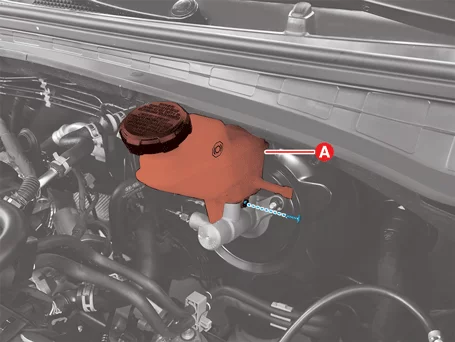
|
| 1.
|
Install in the reverse order of removal.
|
•
|
Install to the specified torque.
|
|
•
|
Check the brake fluid level sensor is securely connected during
installation, poor
connection may cause the brake warning lamp to illuminate.
|
|
•
|
When installing the brake tube, make sure that the flare nuts
is installed in the correct
position.
|
|
|
| 2.
|
Perform in the brake bleeding procedure.
(Refer to Brake System - "Brake Bleeding")
|
| 3.
|
Check the brake fluid leakage and pedal operating condition.
|
Front Brake Caliper Components and Components Location
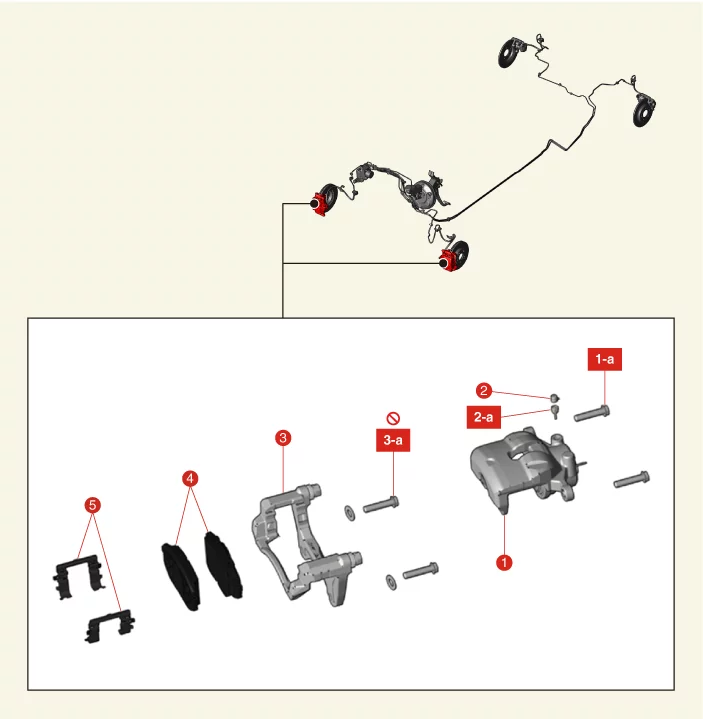
1. Brake Caliper Body
1-a. 21.6 - 31.4 N·m
(2.2 -
3.2 kgf·m, 15.9 - 23.1 lb·ft)
2. Air Bleeding Screw Cap
2-a. 13.7 - 19.6 N·m (1.4 - 2.0
kgf·m, 10.1 -
14.5 lb·ft)
3. Torque Member
3-a. 78.5 - 98.1 N·m (8.0 - 10.0 kgf·m, 57.9 - 72.3 lb·ft)
|
4. Brake Pad
5. Brake Pad Liner
|
Front Brake Caliper Removal and Installation
Tool Name / Number
|
Illustration
|
Description
|
Piston expander
09581 - 11000
|
|
Spreading the front brake caliper piston.
|
| 1.
|
Remove the front wheel and tires.
(Refer to Suspension System - "Wheel")
|
| 2.
|
Disconnect the front brake hose (A) after removing the bolt.
|
Tightening torque :
24.5 - 29.4 N·m (2.5 - 3.0 kgf·m, 18.1 - 21.7 lb·ft)
|
|
Do not reuse the washer (B).
|
|
| 3.
|
Remove the front brake caliper body (A) after removing the bolts.
|
Tightening torque :
21.6 - 31.4 N·m (2.2 - 3.2 kgf·m, 15.9 - 23.1 lb·ft)
|
|
| 4.
|
Remove the brake pads (A).
|
| 5.
|
Remove the brake pad liners (A).
|
| 6.
|
Remove the front torque member (A) after removing the bolts and washers.
|
Tightening torque :
78.5 - 98.1 N·m (8.0 - 10.0 kgf·m, 57.9 - 72.3 lb·ft)
|
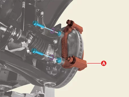
|
Do not reuse the torque member bolts.
|
|
| 1.
|
Install in the reverse order of removal.
|
•
|
Install to the specified torque.
|
|
•
|
Be careful not to damage the piston when pressing it.
|
|
•
|
Be careful not to interfere with the piston when assembling the
caliper body to the
carrier.
|
|
•
|
Press the brake piston using SST (09581 - 11000) when
installing the caliper body.
|
|
|
| 2.
|
Perform in the brake air bleeding procedure.
(Refer to Brake System - "Brake Bleeding")
|
•
|
If air does not occur after the first brake bleed operation,
the 'HCU Air Bleeding Mode'
procedure may be omitted.
|
|
•
|
But if the ESC unit or reservoir tank is replaced, do not skip
the 'HCU Air Bleeding
Mode' procedure.
|
|
|
| 3.
|
Depress the brake pedal several times to ensure that the brake pads are correctly positioned,
then check
operation.
|
| 4.
|
Check the brake fluid leakage and pedal operating condition.
|
Front Brake Disc Components and Components Location
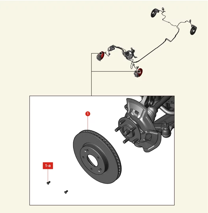
1. Front Brake Disc
1-a. 4.9 - 5.9 N·m (0.5
- 0.6
kgf·m, 3.6 - 4.3 lb·ft, 43.4 - 52.1 lb·in)
|
|
Front Brake Disc On Vehicle Inspection
Disc Cleaning Before Inspection
The rust caused by leaving the vehicle unattended for a long period of time is naturally removed under normal
driving conditions. It may affect thickness and runout measurements, please remove rust on the brake disc for
accurate measurements.
| 1.
|
Check the brake disc for rust.
|
| 2.
|
Spray the cleaning solution on rusted surface of disc.
|
Cleaning solution : Water (300 ml) +
Detergent (15 ml)
|
|
Do not use lubricating, oil-based cleaning agents (wax, rust inhibitors). Poor
braking
performance and risk of fire due to pad friction during braking.
|
|
| 3.
|
Drive the vehicle up to 30 MPH and depress the brake up to stop for complete repeat more than 5
cycles.
|
| 4.
|
Clean the brake disc with clean water.
|
| 5.
|
Check the brake disc for rust.
|
| 6.
|
If rust is not removed, repeat the above procedure again.
|
Front Brake Disc Thickness Check
| 1.
|
Remove the front wheel and tires.
(Refer to Suspension System - "Wheel")
|
| 2.
|
Check the brake disc for damage.
|
| 3.
|
Measure the brake disc thickness (A) and run-out using the micro meter and dial gauge at least
24
locations on the same column along the lines shown in the figure below.
|
Front brake disc thickness (A)
[15", 16" Disc]
Standard : 25 mm (0.98 in.)
Service limit : 23 mm (0.90 in.)
DTV (Disc Thickness Variation) :
Less than 0.015 mm (0.0006 in.) [Circumference direction]
Less than 0.015 mm (0.0006 in.) [Radial direction]
|
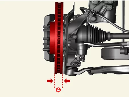
|
| 4.
|
If the thickness difference between each measuring part is greater than standard, resurface or
replace
the brake disc.
|
•
|
Resurface the brake disc according to the method of using the
equipment in possession.
|
|
•
|
If the brake disc is less than or equal to the limit, replace
the brake disc with a new
one.
|
|
|
| 5.
|
Install the front wheel and tires.
(Refer to Suspension System - "Wheel")
|
Front Brake Disc Runout Inspection
| 1.
|
Remove the front wheel and tires.
(Refer to Suspension System - "Wheel")
|
| 2.
|
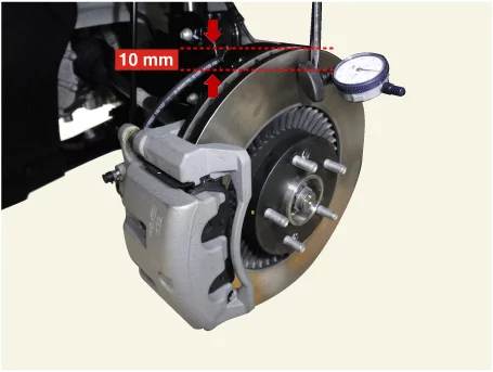
Install the dial gauge perpendicular to the brake disc's external diameter of 10 mm (0.40 in.)
and rotate
the disc to measure the run-out.
|
Brake disc run-out
Service Limit : 0.050 mm (0.0019 in.)
|
|
| 3.
|
If the brake disc run-out exceeds the limit, resurface or replace the brake disc.
|
•
|
Resurface the brake disc according to the method of using the
equipment in possession.
|
|
•
|
If the brake disc is less than or equal to the limit, replace
the brake disc with a new
one.
|
|
|
| 4.
|
Install the front wheel and tires.
(Refer to Suspension System - "Wheel")
|
Front Brake Disc Removal and Installation
Tool Name / Number
|
Illustration
|
Description
|
Piston expander
09581 - 11000
|
|
Spreading the front brake caliper piston.
|
| 1.
|
Remove the front wheel and tires.
(Refer to Suspension System - "Wheel")
|
| 2.
|
Separate the front brake caliper body (A) after removing the bolt.
|
Tightening torque :
21.6 - 31.4 N·m (2.2 - 3.2 kgf·m, 15.9 - 23.1 lb·ft)
|
|
Secure the separated front brake caliper body (A) using a suitable tool such as
a hook (B).
|
|
| 3.
|
Remove the brake pads (A).
|
| 4.
|
Remove the brake pad liners (A).
|
| 5.
|
Remove the front torque member (A) after removing the bolts and washers.
|
Tightening torque :
78.5 - 98.1 N·m (8.0 - 10.0 kgf·m, 57.9 - 72.3 lb·ft)
|
|
Do not reuse the torque member bolts.
|
|
| 6.
|
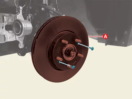
Remove the brake disc (A) after removing the screws.
|
Tightening torque :
4.9 - 5.9 N·m (0.5 - 0.6 kgf·m, 3.6 - 4.3 lb·ft, 43.4 - 52.1 lb·in)
|
|
| 1.
|
Install in the reverse order of removal.
|
•
|
Install to the specified torque.
|
|
•
|
Be careful not to damage the piston when pressing it.
|
|
•
|
Be careful not to interfere with the piston when assembling the
caliper body to the
carrier.
|
|
•
|
Press the brake piston using SST (09581 - 11000) when
installing the caliper body.
|
|
|
| 2.
|
Depress the brake pedal several times to ensure that the brake pads are correctly positioned,
then check
operation.
|
Rear Brake Caliper Components and Components Location
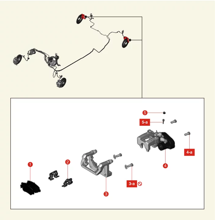
1. Brake Pad
2. Brake Pad Liner
3.
Torque
Member
3-a. 78.5 - 98.1 N·m (8.0 - 10.0 kgf·m, 57.9 - 72.3 lb·ft)
|
4. Brake Caliper Body
4-a. 21.6 - 31.4 N·m
(2.2 -
3.2 kgf·m, 15.9 - 23.1 lb·ft)
5. Air Bleed Screw
5-a. 6.9 - 12.7 N·m (0.7 - 1.3 kgf·m, 5.1 -
9.4 lb·ft)
|
Rear Brake Caliper Removal and Installation
| 1.
|
Perform in the order below with the KDS.
(S/W Management → ABSESP - Braking Control → Brake Pad Change Mode)
|
Refer to the KDS screen for operating conditions and details
|
|
| 2.
|
Disconnect the battery negative ( - ) terminal.
|
| 3.
|
Remove the rear wheel and tires.
(Refer to Suspension System - "Wheel")
|
| 4.
|
Disconnect the EPB connector (A).
|
| 5.
|
Disconnect the brake hose (A) after removing the bolt.
|
Tightening torque :
24.5 - 29.4 N·m (2.5 - 3.0 kgf·m, 18.1 - 21.7 lb·ft)
|
|
Do not reuse the washer (B).
|
|
| 6.
|
Remove the rear brake caliper body (A) after removing the bolts.
|
Tightening torque :
21.6 - 31.4 N·m (2.2 - 3.2 kgf·m, 15.9 - 23.1 lb·ft)
|
|
| 7.
|
Remove the brake pads (A).
|
| 8.
|
Remove the brake pad liners (A).
|
| 9.
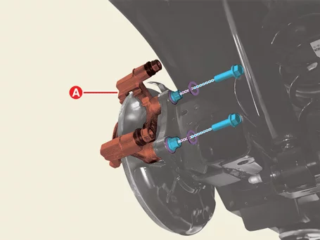
|
Remove the rear torque member (A) after removing the bolts and washers.
|
Tightening torque :
78.5 - 98.1 N·m (8.0 - 10.0 kgf·m, 57.9 - 72.3 lb·ft)
|
|
Do not reuse the torque member bolts.
|
|
| 1.
|
Install in the reverse order of removal.
|
•
|
Install to the specified torque.
|
|
•
|
Observe the following precautions when installing the inner
brake pads. Incorrect
installation may cause noise or degrade brake performance.
- Make sure that the inner brake pad wear indicator (A) is
facing up on the brake
caliper.
- Make sure that the inner brake pad L (LH caliper) or R (RH
caliper) marks are facing up
on the brake caliper.
|
|
•
|
Be careful not to touch the piston when installing the caliper
body to the torque member.
|
|
•
|
When installing the caliper body, use an suitable tool such as
pliers (A) to rotate the
piston clockwise to press it in.
|
|
•
|
Before installing the caliper body, check that the position of
the piston groove (A) is
as shown in the following picture.
|
|
|
| 2.
|
Perform in the brake air bleeding procedure.
(Refer to Brake System - "Brake Bleeding")
|
•
|
If air does not occur after the first brake bleed operation,
the 'HCU Air Bleeding Mode'
procedure may be omitted.
|
|
•
|
But if the ESC unit or reservoir tank is replaced, do not omit
the 'HCU Air Bleeding
Mode' procedure.
|
|
|
| 3.
|
Depress the brake pedal several times to ensure that the brake pads are correctly positioned,
then check
operation.
|
| 4.
|
Check the brake fluid leakage and pedal operating condition.
|
| 5.
|
Perform in the order below with the KDS.
(S/W Management → ABSESP - Braking Control → Brake Pad Change Mode)
|
Refer to the KDS screen for operating conditions and details
|
|
| 6.
|
Apply the parking brake several times and check for normal operation.
|
| 7.
|
Check if the parking brake is operating normally.
|
Rear Brake Disc Components and Components Location
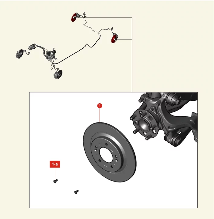
1. Rear Brake Disc
1-a. 4.9 - 5.9 N·m (0.5
- 0.6
kgf·m, 3.6 - 4.3 lb·ft, 43.4 - 52.1 lb·in)
|
|
Rear Brake Disc On Vehicle Inspection
Disc Cleaning Before Inspection
The rust caused by leaving the vehicle unattended for a long period of time is naturally removed under normal
driving conditions. It may affect thickness and runout measurements, please remove rust on the brake disc for
accurate measurements.
| 1.
|
Check the brake disc for rust.
|
| 2.
|
Spray the cleaning solution on rusted surface of disc.
|
Cleaning solution : Water (300 ml) +
Detergent (15 ml)
|
|
Do not use lubricating, oil-based cleaning agents (wax, rust inhibitors). Poor
braking
performance and risk of fire due to pad friction during braking.
|
|
| 3.
|
Drive the vehicle up to 30 MPH and depress the brake up to stop for complete repeat more than 5
cycles.
|
| 4.
|
Clean the brake disc with clean water.
|
| 5.
|
Check the brake disc for rust.
|
| 6.
|
If rust is not removed, repeat the above procedure again.
|
Rear Brake Thickness Check
| 1.
|
Remove the rear wheel and tires.
(Refer to Suspension System - "Wheel")
|
| 2.
|
Check the brake disc for damage.
|
| 3.
|
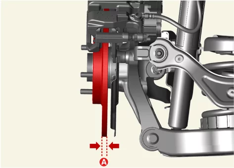
Measure the brake disc thickness (A) and run-out using a micrometer and dial gauge. Measure in
at least
24 points.
|
Rear brake disc thickness (A)
[14" Disc]
Standard : 10 mm (0.39 in.)
Service limit : 8.4 mm (0.33 in.)
[15" Disc]
Standard : 10 mm (0.39 in.)
Service limit : 8.0 mm (0.31 in.)
DTV (Disc Thickness Variation) :
Less than 0.015 mm (0.0006 in.) [Circumference direction]
Less than 0.015 mm (0.0006 in.) [Radial direction]
|
|
| 4.
|
If the thickness difference between each measuring part is greater than standard, resurface or
replace
the brake disc.
|
•
|
Resurface the brake disc according to the method of using the
equipment in possession.
|
|
•
|
If the brake disc is less than or equal to the limit, replace
the brake disc with a new
one.
|
|
|
| 5.
|
Install the rear wheel and tires.
(Refer to Suspension System - "Wheel")
|
Rear Brake Disc Runout Inspection
| 1.
|
Remove the rear wheel and tires.
(Refer to Suspension System - "Wheel")
|
| 2.
|
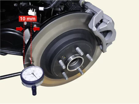
Install the dial gauge perpendicular to the brake disc's external diameter of 10 mm (0.40 in.)
and rotate
the disc to measure the run-out.
|
Brake disc run-out
Service limit : 0.055 mm (0.002 in.) or less.
|
|
| 3.
|
If the brake disc run-out exceeds the limit, resurface or replace the brake disc.
|
•
|
Resurface the brake disc according to the method of using the
equipment in possession.
|
|
•
|
If the brake disc is less than or equal to the limit, replace
the brake disc with a new
one.
|
|
|
| 4.
|
Install the rear wheel and tires.
(Refer to Suspension System - "Wheel")
|
Rear Brake Disc Removal and Installation
| 1.
|
Perform in the order below with the KDS.
(S/W Management → ABSESP - Braking Control → Brake Pad Change Mode)
|
Refer to the KDS screen for operating conditions and details
|
|
| 2.
|
Disconnect the battery negative ( - ) terminal.
|
| 3.
|
Remove the rear wheel and tires.
(Refer to Suspension System - "Wheel")
|
| 4.
|
Disconnect the EPB connector (A).
|
| 5.
|
Separate the rear brake caliper body (A) after removing the bolts.
|
Tightening torque :
21.6 - 31.4 N·m (2.2 - 3.2 kgf·m, 15.9 - 23.1 lb·ft)
|
|
| 6.
|
Remove the brake pads (A).
|
| 7.
|
Remove the brake pad liners (A).
|
| 8.
|
Remove the rear torque member (A) after removing the bolts and washers.
|
Tightening torque :
78.5 - 98.1 N·m (8.0 - 10.0 kgf·m, 57.9 - 72.3 lb·ft)
|
|
Do not reuse the torque member bolts.
|
|
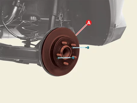
| 9.
|
Remove the brake disc (A) after removing the screw.
|
Tightening torque :
4.9 - 5.9 N·m (0.5 - 0.6 kgf·m, 3.6 - 4.3 lb·ft, 43.4 - 52.1 lb·in)
|
|
| 1.
|
Install in the reverse order of removal.
|
•
|
Install to the specified torque.
|
|
•
|
Observe the following precautions when installing the inner
brake pads. Incorrect
installation may cause noise or degrade brake performance.
- Make sure that the inner brake pad wear indicator (A) is
facing up on the brake
caliper.
- Make sure that the inner brake pad L (LH caliper) or R (RH
caliper) marks are facing up
on the brake caliper.
|
|
•
|
Be careful not to touch the piston when installing the caliper
body to the torque member.
|
|
•
|
When installing the caliper body, use an suitable tool such as
pliers (A) to rotate the
piston clockwise to press it in.
|
|
•
|
Before installing the caliper body, check that the position of
the piston groove (A) is
as shown in the following picture.
|
|
|
| 2.
|
Perform in the order below with the KDS.
(S/W Management → ABSESP - Braking Control → Brake Pad Change Mode)
|
Refer to the KDS screen for operating conditions and details
|
|
| 3.
|
Apply the parking brake several times and check for normal operation.
|
| 4.
|
Check if the parking brake is operating normally.
|
Stop Lamp Switch Components and Components Location
1. Stop Lamp Switch
2. Return Spring
3.
Brake
Pedal Pad
|
4. Brake Pedal Member Assembly
4-a. 16.7 -
25.5 N·m
(1.7 - 2.6 kgf·m, 12.3 - 18.8 lb·ft)
|
Stop Lamp Switch On Vehicle Inspection
| 1.
|
The brake system can quickly diagnosed for problems by using the KDS (Refer to "DTC guide").
| (1)
|
Trouble code diagnosis : Inspection and display trouble code (DTC)
(Refer to DTC guide when fault code is found.)
|
| (2)
|
S/W Management : Controlling other features including system option setting and
zero point
adjustment.
|
Refer to the KDS screen for operating conditions and details
|
|
|
Stop Lamp Switch Description and Operation
| Description and Operation |
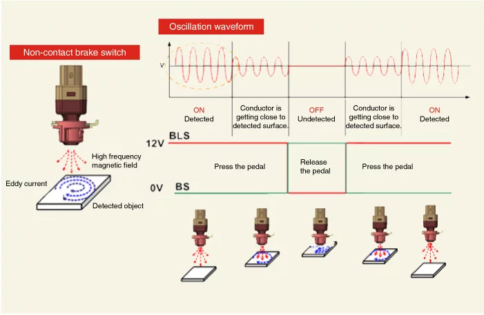
Operation principle of inductive non-contact switch
| 1.
|
Use the high-frequency magnetic field and the induced current that is generated by oscillation
(to
approved voltage) of the coil in the switch.
|
| 2.
|
The eddy current is generated on surface of metal by self inductance effect if there is metal
in high
frequency magnetic field.
|
| 3.
|
The eddy current that is generated decreases the high frequency magnetic field as much as
amount of
generated by disturbing the switch's magnetic flux.
|
| 4.
|
ON-OFF by judging whether high voltage magnetic field is attenuates or not(calculate the
voltage
difference by length between metal and coil).
|
Stop Lamp Switch Replacement
| 1.
|
Remove the crash pad lower panel.
(Refer to Body - "Crash Pad Panel")
|
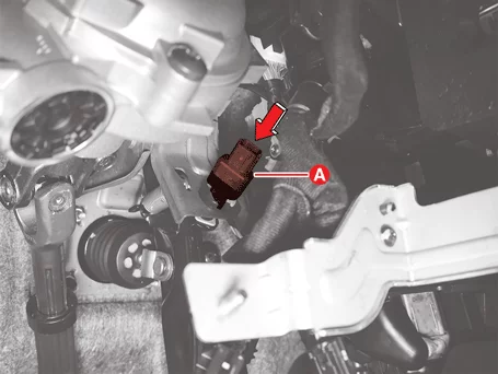
| 2.
|
Disconnect the stop lamp switch connector (A).
|
| 3.
|
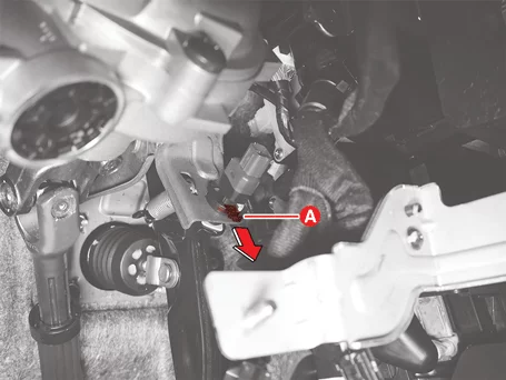
Pull the locking plate (A) in the direction of the arrow.
|
| 4.
|
Turn the stop lamp switch (A) counterclockwise about 45 degrees and remove it.
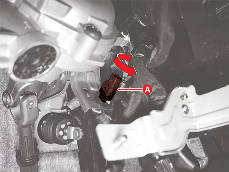
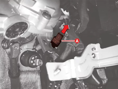
|
| 5.
|
Install the stop lamp switch (A) and rotate it 45 degrees clockwise.
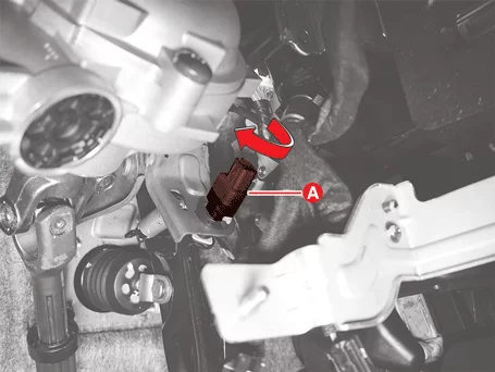
|
| 6.
|
Push the locking plate (A) in the direction of the arrow to install it.
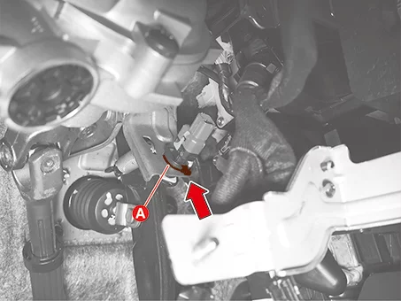
|
| 7.
|
Check the stop lamp switch clearance (A).
|
Clearance (A) : 1.0 - 2.0 mm (0.03 -
0.07 in.)
|
|
If the stop lamp switch clearance is out of the specified value, reinstall the
stop lamp switch.
|
|
| 8.
|
Connect the stop lamp switch connector (A).
|
Stop Lamp Switch Adjustment
Adjusting Stop Lamp Switch Clearance
| 1.
|
Check the stop lamp switch clearance (A).
|
Stop lamp switch clearance (A) : 1.0 -
2.0 mm (0.03 - 0.07
in.)
|
|
| 2.
|
If the clearance exceeds the limit, remove the stop lamp switch and check for damage to
surrounding parts
such as clips.
|
| 3.
|
If there is no damage, install the stop lamp switch and recheck the clearance.
|
Vacuum Pump - G 1.6 T-GDI GAMMA II Removal and Installation
| 1.
|
Remove the battery tray.
G 1.6 T-GDI GAMMA II (Refer to Engine Electrical System -
"Battery")
|
| 2.
|
Separate the fuel line holders (B) from the engine wiring harness (A).
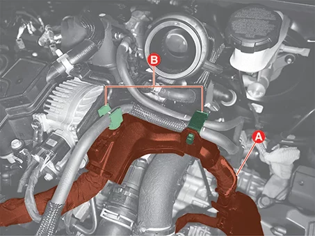
|
| 3.
|
Separate the wiring protector (A) after removning the nuts.
|
Tightening torque :
4.9 - 7.8 N·m (0.5 - 0.8 kgf·m, 3.6 - 5.8 lb·ft)
|
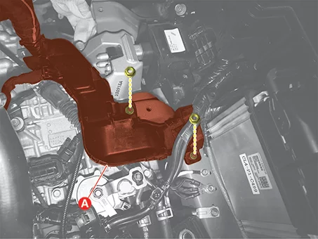
|
| 4.
|
Separate the wiring protector bolt (A) and ground wiring bolt (B).
|
Tightening torque :
(A) : 6.8 - 9.8 N·m (0.7 - 1.0 kgf·m, 5.0 - 7.2 lb·ft)
(B) : 6.8 - 9.8 N·m (0.7 - 1.0 kgf·m, 5.0 - 7.2 lb·ft)
|
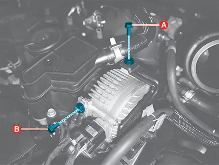
|
| 5.
|
Separate the engine wiring harness bolts (A).
|
Tightening torque :
6.8 - 9.8 N·m (0.7 - 1.0 kgf·m, 5.0 - 7.2 lb·ft)
|
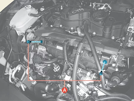
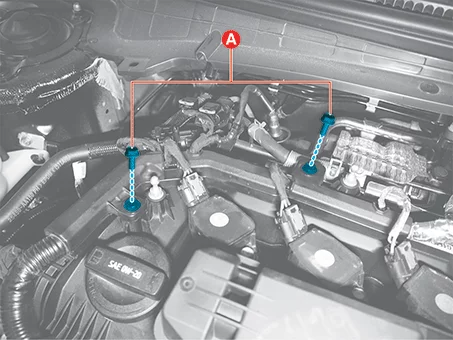
|
| 6.
|
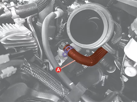
Disconnect the brake vacuum hose (A) after releasing the clamps.
|
| 7.
|
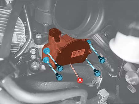
Remove the vacuum pump (A) after removing the bolts.
|
Tightening torque :
18.6 - 23.5 N·m (1.9 - 2.4 kgf·m, 13.7 - 17.3 lb·ft)
|
|
| 1.
|
Install in reverse order of removal.
|
Install to the specified torque.
|
|
Other information:
Kia K4 (CL4) 2025-2026 Service Manual: Over-The-Air (OTA) software update
The Over-The-Air (OTA) software update feature provides a seamless way to keep your Kia K4 performing at its peak. By wirelessly downloading the latest firmware and system improvements, this feature ensures that your Kia K4 always benefits from the most recent technological enhancements without requiring a visit to a service center. To utilize these convenient remote updates, you must maintain an active Kia Connect subscription.
Kia K4 (CL4) 2025-2026 Service Manual: Driver Attention Warning (DAW)
Driver Attention Warning function
The Driver Attention Warning (DAW) system in your Kia K4 continuously monitors your driving patterns, vehicle stability, and inputs. When the system detects signs of reduced alertness or potential fatigue, the Kia K4 will proactively recommend a rest break to ensure your continued safety on the road.
Leading Vehicle Departure Alert function
The Leading Vehicle Departure Alert (LVDA) is a convenient feature for the Kia K4 that provides an audible and visual notification to the driver when the vehicle ahead of you begins to move from a stationary position, such as at a traffic light or in stop-and-go traffic.