|
•
|
This video was created using 3D graphics to help understand the vehicle
maintenance manual.
|
|
•
|
There may be some differences from actual vehicles.
|
|
•
|
The location and repair procedures of the parts may vary depending on vehicle
model, model year,
region, and specifications.
|
|
•
|
Check the KDS Guide for detailed information on how to use the KDS.
|
|
•
|
Check the manual for detailed maintenance procedures.
|
|
•
|
Unauthorized reproduction, distribution, or sharing of this video is
prohibited.
|
|
Cylinder Head Installation
(Click to play)

Video: Cylinder Head Installation
Tool Name / Number
|
Illustration
|
Description
|
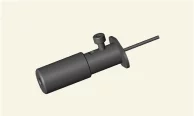
HLA air bleed tool
0K246 - L8000
|
|
Used to air bleed HLA
|
|
•
|
Thoroughly clean all parts to be assembled.
|
|
•
|
Do not reuse Cylinder head gasket and exhaust manifold gasket.
|
|
•
|
Do not reuse the cylinder head bolt.
|
|
•
|
The cylinder head gasket is made of metal, so be careful not to bend it.
|
|
•
|
Rotate the crankshaft to place the No.1 cylinder piston at the at the TDC.
|
|
•
|
Clean surely so that oil, dirt, and scratches are not on the gasket contact
surface of the
cylinder block and cylinder head.
|
|
| 1.
|
Install the cylinder head gasket.
| (1)
|
Clean the cylinder head and gasket contact surface of the cylinder block so
that foreign objects
are not on it like oil, dirt, etc.
|
| (2)
|
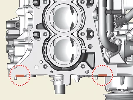
Apply liquid gasket on the top of the cylinder block.
|
Bead width : 2.0 - 3.0
mm (0.0787 - 0.1181 in.)
Sealant specifications :
THREEBOND 1217H / LOCTITE
5900H or equivalent
|
|
| (3)
|
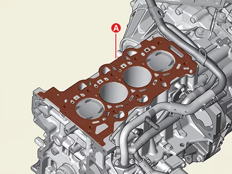
Install the cylinder head gasket (A) on the cylinder block.
|
•
|
Be careful not to change the mounting direction
of the cylinder head gasket.
|
|
•
|
Do not reuse cylinder head gaskets.
|
|
|
| (4)
|
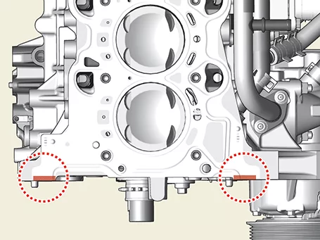
Apply liquid sealant on the top of the cylinder head gasket.
|
Bead width : 2.0 - 3.0
mm (0.0787 - 0.1181 in.)
Sealant specifications :
THREEBOND 1217H / LOCTITE
5900H or equivalent
|
|
|
| 2.
|
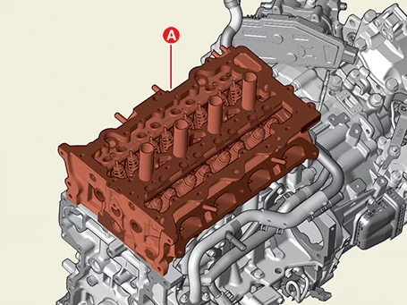
Install the cylinder head.
| (1)
|
Install the cylinder head (A) slowly to prevent damage to the head gasket.
|
| (2)
|
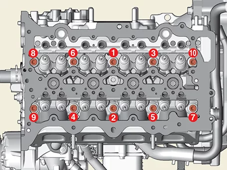
Tighten the cylinder head bolts several times according to the tightening
sequence below.
|
Tightening torque
Step 1 : 29.4 N·m (3.0
kgf·m, 21.7 lb·ft)
Step 2 : 90°
Step 3 : 90°
|
|
•
|
Always use a new cylinder head bolts and
cylinder head bolt washers.
|
|
•
|
Assemble the cylinder head gasket and cylinder
head within 5 minutes after
applying the liquid sealant.
|
|
•
|
Remove the protruding sealants within 5 minutes
after assembling the cylinder
head bolts.
|
|
•
|
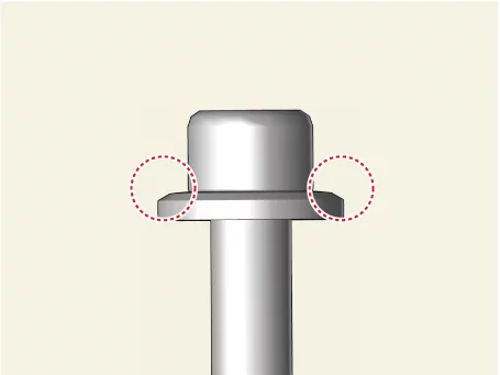
When installing the cylinder head bolts,
distinguish the vertical direction of
the cylinder head bolt washers to ensure that
the round and chamber parts are facing
the cylinder head bolt head.
|
|
|
|
| 3.
|
Perform the HLA air bleeding.
| (1)
|
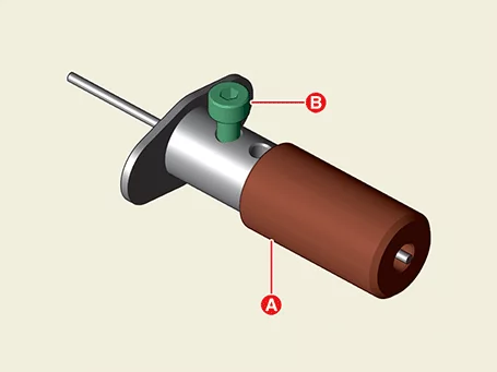
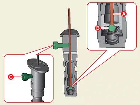
Remove the cover (A) of the special tool (0K246 - L8000) and loosen the bolt
(B).
|
Do not remove the bolt (B).
|
|
| (2)
|
Tighten the bolt (C) with the special tool (0K246 - L8000) with the pin (A) on
the ball (B).
Be careful not to push down the pin (A) too hard as the weight of the ball is
only a few grams
(g).
|
| (3)
|
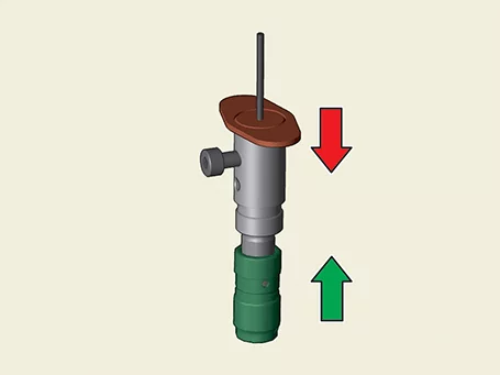
Hold HLA and special tool (0K246 - L8000) in oil with your hand and press it
4-5 times in the
direction of the arrow.
|
| (4)
|
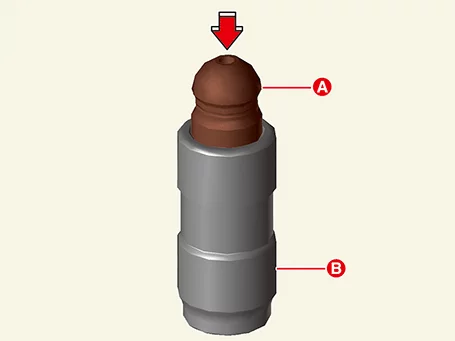
Hold the bottom (B) of the HLA filled with engine oil and press the cap (A)
with your hands,
repeating procedure 3 until the cap (A) is not pressed.
|
|
| 4.
|
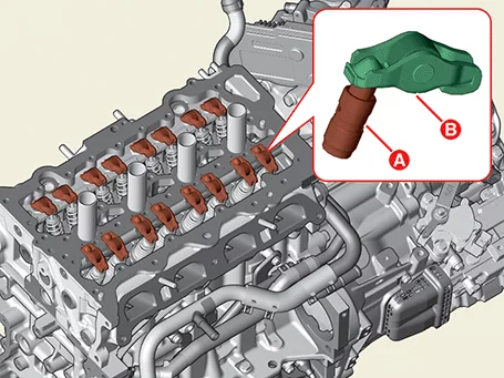
Install the Hydraulic Lash Adjusters (HLA) (A) and swing arms (B).
| (1)
|
Before assembling the HLA, stand it upright so that the engine oil inside does
not overflow and
dust does not adhere.
|
| (2)
|
Carefully insert the HLA into the cylinder head, taking care not to overflow
the engine oil
inside the HLA. If engine oil has spilled, perform HLA air bleed operation.
|
|
| 5.
|
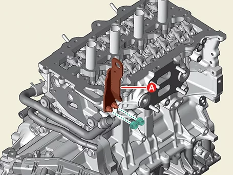
Install the engine hanger (A) and then tighten the nut.
|
Tightening torque :
18.6 - 23.5 N·m (1.9 - 2.4 kgf·m, 13.7 - 17.4 lb·ft)
|
|
| 6.
|
Install the cam carrier.
| (1)
|
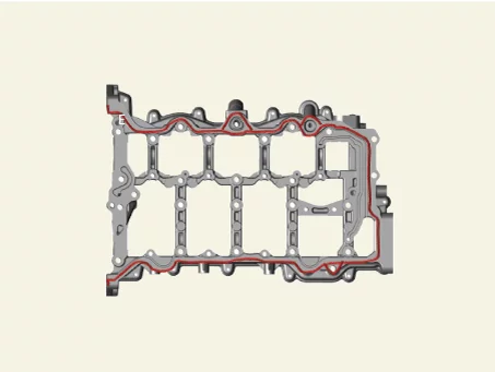
Apply a liquid gasket to the mounting surface of the cam carrier.
|
Bead width : 2.5 - 3.5
mm (0.0984 - 0.1377 in.)
Sealant specifications :
THREEBOND 1217H / LOCTITE
5900H or equivalent
|
|
| (2)
|
The cam carrier is installed accurately based on the dowel pin of the carrier
and the hole on the
upper surface of the cylinder head.
|
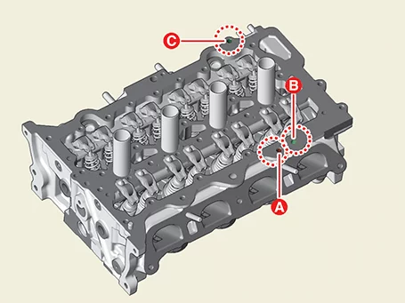
When install the cam carrier to the cylinder head, be careful
that the sealant does not
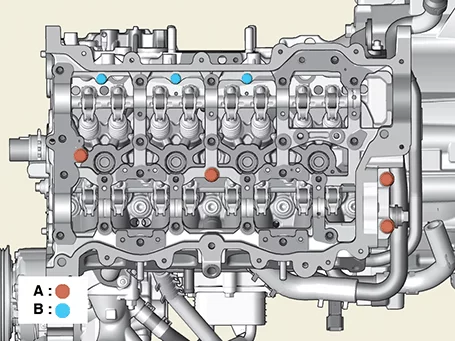
enter the oil level gauge hole (A), the positive crankcase
ventilation (PCV) hole (B), and
the high pressure fuel pump adapter fixing hole (C).
|
|
| (3)
|
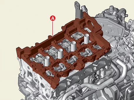
Install the cam carrier (A).
|
| (4)
|
Install the cam carrier mounting bolts (A, B).
|
Tightening torque
A : 9.8 - 11.8 N·m (1.0
- 1.2 kgf·m, 7.2 - 8.7
lb·ft)
B : 18.6 - 22.6 N·m (1.9
- 2.3 kgf·m, 13.7 - 16.6
lb·ft)
|
|
•
|
Install the cam carrier within 5 minutes after
applying the sealant.
|
|
•
|
Install the camshaft bearing cap within 5
minutes of assembling the cam carrier.
|
|
•
|
The engine running or pressure test should not
be performed within 30 minutes
after assembling the cam carrier.
|
|
•
|
After attaching the cam carrier to the cylinder
head, check whether the sealant
has entered the oil level gauge hole and the
positive crankcase ventilation (PCV)
hole.
|
|
•
|
After attaching the cam carrier to the cylinder
head, check whether the swing arm
is detached normally.
|
|
|
|
| 7.
|
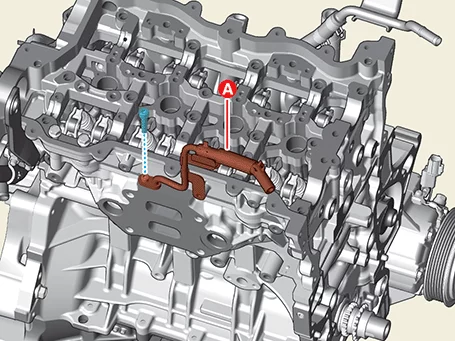
Install the turbocharger water outlet hose and pipe (A) and then tighten the bolts.
|
Tightening torque :
9.8 - 11.8 N·m (1.0 - 1.2 kgf·m, 7.2 - 8.7 lb·ft)
|
|
When assembling degassing hose (A), if the O-ring is not inserted vertically
into head machining
hole, leakage may occur due to O-ring is not sealed.
|
|
| 8.
|
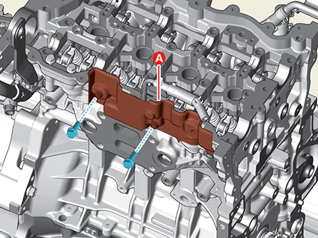
Install the cylinder head cover heat protector (A) and then tighten the bolts.
|
Tightening torque :
9.8 - 11.8 N·m (1.0 - 1.2 kgf·m, 7.2 - 8.7 lb·ft)
|
|
| 9.
|
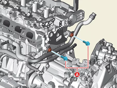
Install the heater pipe mounting bolt (A).
|
Tightening torque :
14.7 - 21.6 N·m (1.5 - 2.2 kgf·m, 10.8 - 15.9 lb·ft)
|
|
| 10.
|
Install in reverse order of removal.
|
•
|
Install the cylinder head to the specified torque.
|
|
•
|
When installing the quick connector hose, make sure it is
properly installed.
|
|
|
| 11.
|
Fill with coolant.
(Refer to Cooling System - "Coolant")
|
Be sure to add coolant according to the ITM coolant refill method.
|
|
| 12.
|
Fill the engine with oil.
(Refer to Lubrication System - "Engine Oil")
|
Other information:
Kia K4 (CL4) 2025-2026 Service Manual: Parking Distance Warning (PDW):
The Forward, Side, and Reverse Parking Distance Warning (PDW) system in your Kia K4 utilizes sophisticated front, side, and rear ultrasonic sensors. This system is engineered to detect and alert you if a person, animal, or object enters a specific proximity zone while your Kia K4 is either stationary or moving at low speeds, providing added confidence during parking maneuvers.