Contents:
Components and Components Location
| Components and Components Location |
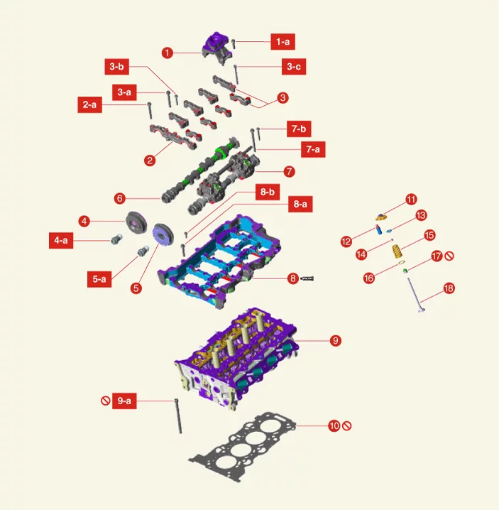
1. High Pressure
Fuel
Pump Bracket
1-a. 18.6 - 23.5 N·m (1.9 - 2.4 kgf·m, 13.7 - 17.4 lb·ft)
2. Camshaft Front
Bearing
Cap
2-a. Step 1 : 9.8 - 11.8 N·m (1.0 - 1.2 kgf·m, 7.2 - 8.7 lb·ft)
2-a. Step 2 : 18.6 - 22.6
N·m (1.9 -
2.3 kgf·m, 13.7 - 16.6 lb·ft)
3. Camshaft Bearing Cap
3-a. Step 1 : 9.8 - 11.8 N·m (1.0 - 1.2
kgf·m, 7.2
- 8.7 lb·ft)
3-a. Step 2 : 18.6 - 22.6 N·m (1.9 - 2.3 kgf·m, 13.7 - 16.6 lb·ft)
3-b. Step 1 :
4.9 - 6.9
N·m (0.5 - 0.7 kgf·m, 3.6 - 5.1 lb·ft, 43.4 - 60.8 lb·in)
3-b. Step 2 : 9.8 - 11.8 N·m (1.0 - 1.2
kgf·m,
7.2 - 8.7 lb·ft)
3-c. Step 1 : 9.8 - 11.8 N·m (1.0 - 1.2 kgf·m, 7.2 - 8.7 lb·ft)
3-c. Step 2 :
18.6 -
22.6 N·m (1.9 - 2.3 kgf·m, 13.7 - 16.6 lb·ft)
4. Exhaust CVVT Assembly
4-a. Step 1 : 22.6 -
26.5 N·m
(2.3 - 2.7 kgf·m, 16.6 - 19.5 lb·ft)
4-a. Step 2 : 32 - 36°
5. Intake CVVT Assembly
5-a.
Step 1 :
22.6 - 26.5 N·m (2.3 - 2.7 kgf·m, 16.6 - 19.5 lb·ft)
5-a. Step 2 : 32 - 36°
6. Exhaust
Camshaft
|
7. CVVD Assembly
7-a. Step 1 : 9.8 - 11.8 N·m (1.0 - 1.2 kgf·m, 7.2 - 8.7 lb·ft)
7-a. Step 2 : 18.6 - 22.6 N·m
(1.9 -
2.3 kgf·m, 13.7 - 16.6 lb·ft)
7-b. Step 1 : 4.9 - 6.9 N·m (0.5 - 0.7 kgf·m, 3.6 - 5.1 lb·ft,
43.4 - 60.8
lb·in)
7-b. Step 2 : 9.8 - 11.8 N·m (1.0 - 1.2 kgf·m, 7.2 - 8.7 lb·ft)
8. Cam Carrier
8-a.
18.6 -
22.6 N·m (1.9 - 2.3 kgf·m, 13.7 - 16.6 lb·ft)
8-b. 9.8 - 11.8 N·m (1.0 - 1.2 kgf·m, 7.2 - 8.7
lb·ft)
9.
Cylinder Head
9-a. Step 1 : 29.4 N·m (3.0 kgf·m, 21.7 lb·ft)
9-a. Step 2 : 90°
9-a. Step 3
:
90°
10. Cylinder Head Gasket
11. Swing Arm
12. Hydraulic Lash Adjuster (HLA)
13.
Retainer
14.
Retainer Lock
15. Valve Spring
16. Valve Spring Seat
17. Valve Stem Seal
18. Valve
|
Cylinder Head Cover Components and Components Location
| Components and Components Location |
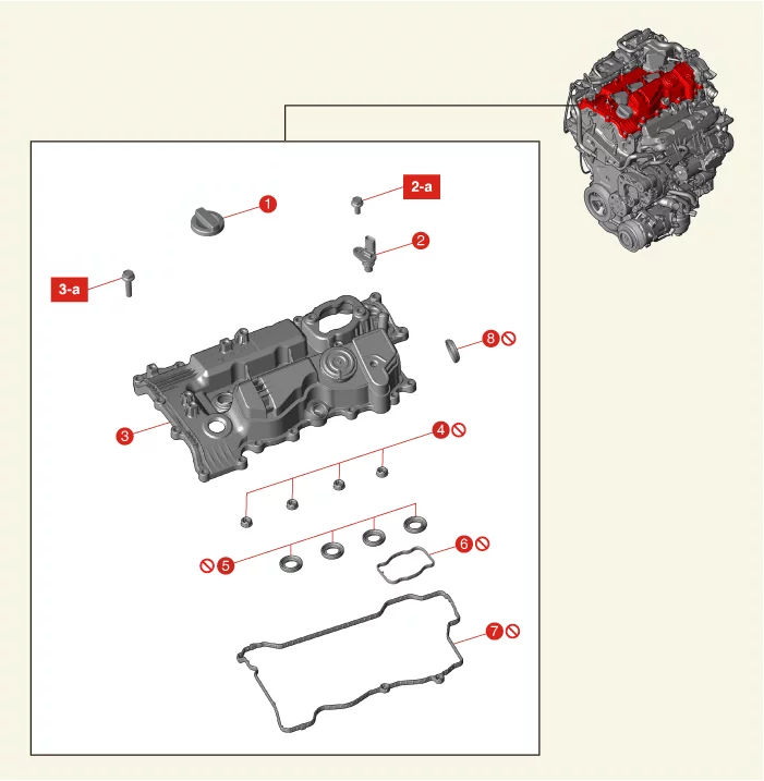
1. Filler Cap
2.
Exhaust
Camshaft Position Sensor (CMPS)
2-a. 9.8 - 11.8 N·m (1.0 - 1.2 kgf·m, 7.2 - 8.7 lb·ft)
3.
Cylinder
Head Cover
3-a. Step 1 : 3.9 - 5.9 N·m (0.4 - 0.6 kgf·m, 2.9 - 4.3 lb·ft, 34.7 - 52.1
lb·in)
3-a. Step 2
: 7.8 - 9.8 N·m (0.8 - 1.0 kgf·m, 5.8 - 7.2 lb·ft)
|
4. Center Bolt
Gasket
5.
Oil Seal
6. High Pressure Fuel Pump Gasket
7. Cylinder Head Cover Gasket
8. Oil seal
|
Cylinder Head Cover Removal
|
•
|
Use a fender cover to protect the painted surface.
|
|
•
|
Be careful not to damage the connector when disconnecting.
|
|
|
Mark wiring and hoses to prevent incorrect connections.
|
| 1.
|
Release the residual pressure in fuel line.
(Refer to Fuel Delivery System - "Release Residual Pressure in
Fuel
Line")
|
| 2.
|
Disconnect the battery negative ( - ) terminal.
|
| 3.
|
Remove the engine cover.
(Refer to Engine and Transaxle Assembly - "Engine
Cover")
|
| 4.
|
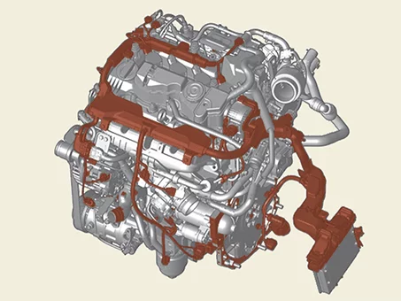
Remove the control wiring connectors and harness clamps around the cylinder head cover, then
remove the
wiring protectors.
|
Tightening torque :
7.8 - 11.8 N·m (0.8 - 1.2 kgf·m, 5.8 - 8.7 lb·ft)
|
|
| 5.
|
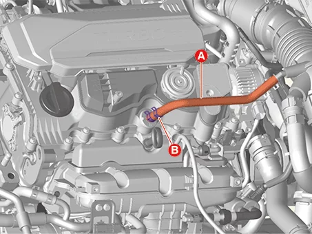
Disconnect the fresh air hose (A) after releasing the clamp (B).
|
| 6.
|
Disconnect the breather hose (A) after releasing the clamp.
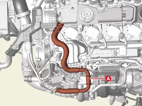
|
| 7.
|
Remove the high pressure fuel pump.
(Refer to Engine Control / Fuel System - "High Pressure Fuel
Pump")
|
| 8.
|
Remove the ignition coil.
(Refer to Engine Electrical System - “Ignition Coil")
|
| 9.
|
Remove the CVVD actuator.
(Refer to Engine Control / Fuel System - "CVVD
actuator")
|
| 10.
|
Remove the oil filler cap (A).
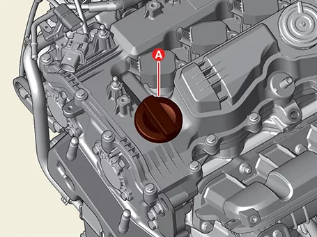
|
| 11.
|
Remove the cylinder head cover (A), after removing the bolt.
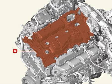
|
Cylinder Head Cover Installation
| 1.
|
Install the cylinder head cover.
| (1)
|
Install the cylinder head cover gasket (A).
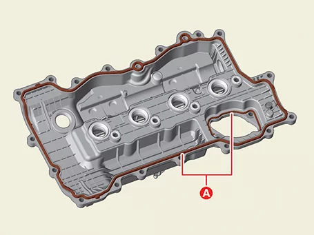
|
Do not reuse the cylinder head cover gasket (A).
|
|
| (2)
|
Remove the hardened sealant on the top of the cylinder head and timing chain
cover before
assembling the cylinder head cover.
|
| (3)
|
After applying the sealant to the parts indicated on the timing chain cover and
the upper part of
the cylinder head, assemble within 5 minutes.
|
Bead width : 2.0 - 3.0
mm (0.0787 - 0.1181 in.)
Sealant specifications :
THREEBOND 1217H / LOCTITE
5900H or equivalent
|
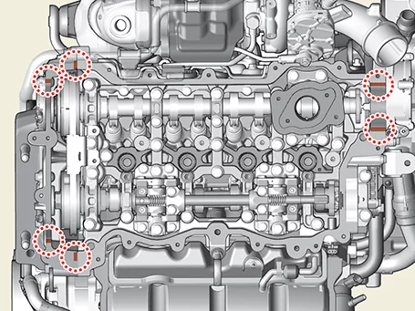
|
| (4)
|
Install the cylinder head cover (A) and then tighten the bolts.
|
•
|
According to the sequence in the figure,
tighten the whole with 1st torque and
then tighten with 2nd torque in that order.
|
Tightening
torque
Step 1 : 3.9 - 5.9 N·m (0.4 -
0.6 kgf·m, 2.9 - 4.3 lb·ft, 34.7
- 52.1
lb·in)
Step 2 : 7.8 - 9.8 N·m (0.8 -
1.0 kgf·m, 5.8 - 7.2 lb·ft)
|
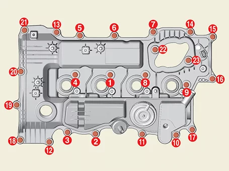
|
|
•
|
Clean the oil, cutting oil, etc. on the upper
part of the luggage cam carrier
before installing the cylinder head cover.
|
|
•
|
Check to see if the gasket contacts are clean
and thin.
|
|
•
|
Do not fill the engine with oil at least 30
minutes after assembly.
|
|
•
|
Do not operate the engine or pressurize the
inside of the engine before 30
minutes after assembling the cylinder head
cover.
|
|
|
|
| 2.
|
Install in reverse order of removal.
|
Install to the specified torque.
|
|
| 4.
|
Perform the CVVD learning with the KDS.
(S/W Management → Engine Control → CVVD Learning)
|
Refer to the KDS screen for operating conditions and details
|
|
CVVT & Exhaust Camshaft Description and Operation
The Continuous Variable Valve Timing (CVVT) system uses ECM control signals that vary with engine RPM and load
to
advance or retard the timing of opening/closing the intake or exhaust valve.
The valve overlap and underlap occurs between intake / exhaust valves due to the control of the CVVT system. It
reduces pumping loss, exhaust gas, and occurs internal EGR, and increases combustion stability, volumetric
efficiency, fuel efficiency by increasing positive work, increases engine performance.The system consists of a
CVVT
oil control valve (OCV) that receives a Pulse Width Modulation (PWM) signal from the ECM and changes a path of
engine oil to supply or discharge oil to a cam phaser, and a cam phaser that changes the phase of the camshaft
with
hydraulic pressure of engine oil.
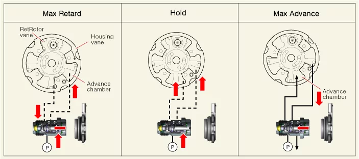
The oil from the CVVT oil control valve changes the phase of the cam shaft by advancing or retarding the cam
shaft by rotating the rotor connected to the cam shaft inside the cam phaser.
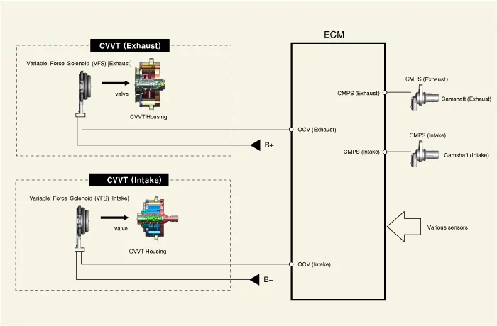
The CVVT system operates in a structure of rotating the rotor vane by hydraulic pressure by supplying oil to
the
advance chamber or the retard chamber through flow path control of the CVVT oil control valve (OCV).
|
•
|
The variable force solenoid (VFS) changes its force depending on the PWM duty
to control the
stroke of the OCV.
|
|
•
|
It also controls the lock, unlock, advanced, retarded, and holding functions.
|
|
Intake CVVT and exhaust CVVT
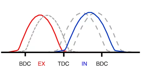
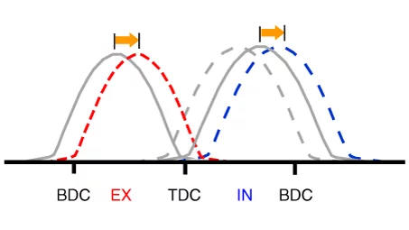
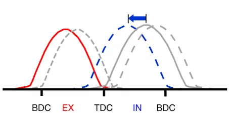
[CVVT System Mode]
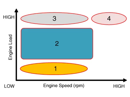
(1) Low Speed/Low Load
|
(2) Partial Load
|
|
|
|
(3) Low Speed/High Load
|
(4) High Speed/High Load
|
|
|
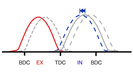
|
Driving Condition
|
Exhaust valve
|
Intake valve
|
Valve timing
|
Improves
|
Valve timing
|
Improves
|
(1) Low Speed/Low Load
|
Completely Advance
|
|
•
|
Improvement of combustion stability
|
|
Middle
|
|
•
|
Improvement of combustion stability
|
|
(2) Partial Load
|
Retard
|
Reduction of HC
|
Retard
|
Reduced intake valve closing time reduces pumping losses.
|
(3) Low Speed/High Load
|
Completely Advance
|
Reduction of pumping loss
|
Advance
|
Improvement of volumetric efficiency
|
(4) High Speed/High Load
|
Completely Advance
|
Reduction of pumping loss
|
Advance
|
Improvement of volumetric efficiency
|
CVVT & Exhaust Camshaft Removal
|
•
|
This video was created using 3D graphics to help understand the vehicle
maintenance manual.
|
|
•
|
There may be some differences from actual vehicles.
|
|
•
|
The location and repair procedures of the parts may vary depending on vehicle
model, model year,
region, and specifications.
|
|
•
|
Check the KDS Guide for detailed information on how to use the KDS.
|
|
•
|
Check the manual for detailed maintenance procedures.
|
|
•
|
Unauthorized reproduction, distribution, or sharing of this video is
prohibited.
|
|
CVVT & Exhaust Camshaft Removal
(Click to play)

Video: CVVT & Exhaust Camshaft Removal
| Continuously Variable Valve Timing (CVVT) and exhaust
camshafts
|
| 1.
|
Remove the cylinder head cover.
(Refer to Cylinder Head Assembly - "Cylinder Head
Cover")
|
| 2.
|
Remove the vacuum pump.
(Refer to Brake System - "Vacuum Pump")
|
| 3.
|
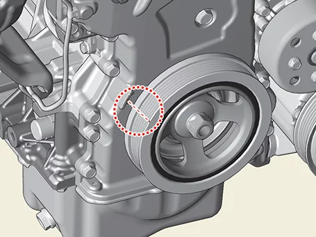
Turn the crankshaft damper pulley clockwise to bring the piston of cylinder 1 to compression
top dead
center so that the timing mark on the timing chain cover matches the groove on the damper
pulley.
|
| 4.
|
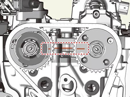
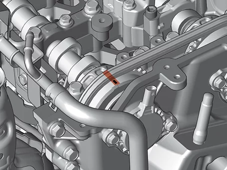
Rotate so that the TDC marks on the intake Continuously Variable Valve Timing (CVVT) sprocket
and exhaust
CVVT sprocket are aligned with the top surface of the cylinder head so that cylinder 1 is at
compression top
dead center.
|
| 5.
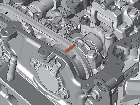
|
Permanent ink markings on chain links matching intake and exhaust CVVT timing markings.
[Intake CVVT]
[Exhaust CVVT]
|
| 6.
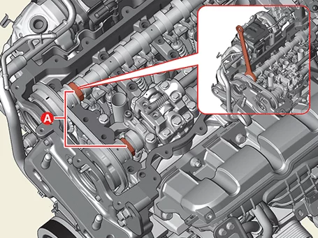
|
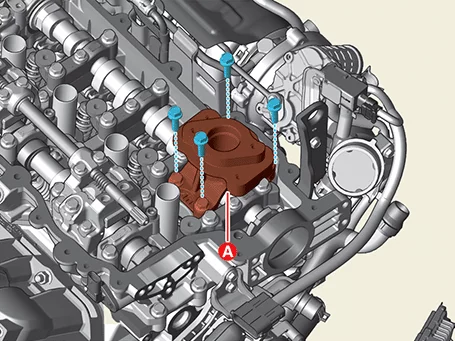
Remove the high pressure fuel pump brackets (A) after removing the bolts.
|
| 7.
|
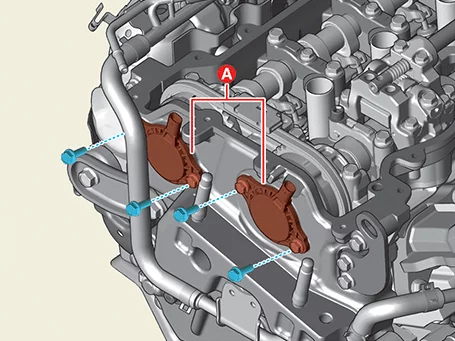
Remove the intake and exhaust Variable Force Solenoid valves (VFS) (A) after removing the bolt.
|
Tightening torque :
9.8 - 11.8 N·m (1.0 - 1.2 kgf·m, 7.2 - 8.7 lb·ft)
|
|
| 8.
|
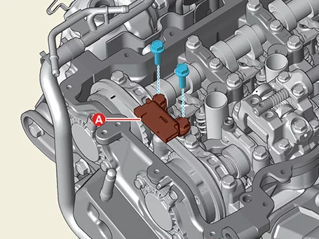
Remove the cam to cam guide (A), after removing the bolts.
|
Tightening torque :
9.8 - 11.8 N·m (1.0 - 1.2 kgf·m, 7.2 - 8.7 lb·ft)
|
|
| 9.
|
Remove the camshaft front bearing cap (A) and camshaft bearing cap (B), after removing the
bolt.
|
Tightening torque :
A(M8) step 1 : 9.8 - 11.8 N·m (1.0 - 1.2 kgf·m, 7.2 - 8.7 lb·ft)
A(M8) step 2 : 18.6 - 22.6 N·m (1.9 - 2.3 kgf·m, 13.7 - 16.6 lb·ft)
B(M6) step 1 : 4.9 - 6.9 N·m (0.5 - 0.7 kgf·m, 3.6 - 5.1 lb·ft)
B(M6) step 2 : 9.8 - 11.8 N·m (1.0 - 1.2 kgf·m, 7.2 - 8.7 lb·ft)
B(M8) step 1 : 9.8 - 11.8 N·m (1.0 - 1.2 kgf·m, 7.2 - 8.7 lb·ft)
B(M8) step 2 : 18.6 - 22.6 N·m (1.9 - 2.3 kgf·m, 13.7 - 16.6 lb·ft)
|
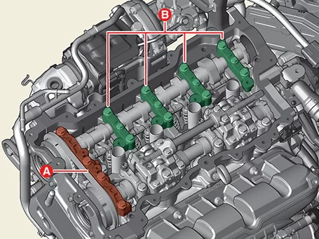
|
| 10.
|
Remove the service hole cover bolt (A).
|
Tightening torque :
27.5 - 30.4 N·m (2.8 - 3.1 kgf·m, 20.3 - 22.4 lb·ft)
|
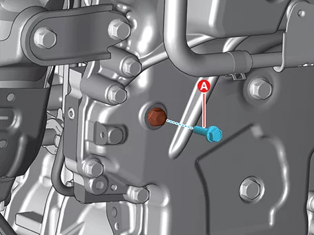
|
| 11.
|
Install the jack (A) to the edge of oil pan to support the engine.
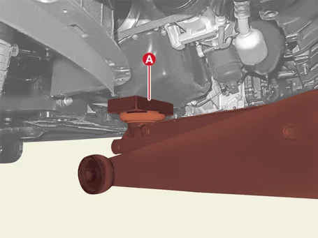
|
Put a rubber pad between the lower oil pan and the jack to prevent damage to
the oil pan.
|
|
| 12.
|
Remove the engine mounting bracket.
(Refer to Engine And Transaxle Assembly - "Engine
Mounting")
|
| 13.
|
Use a jack to lift the engine to free up work space.
|
| 14.
|
Using a fine awl, etc. (A), lower the ratchet plate (B) of the timing chain tensioner downward
to release
the lock.
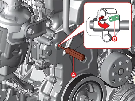
|
| 15.
|
Remove the exhaust OCV and center bolt (A) and intake OCV and center bolt (B).
|
Tightening torque :
Step 1: 22.6 - 26.5 N·m (2.3 - 2.7 kgf·m, 16.6 - 19.5 lb·ft)
Step 2 : 32 - 36°
|
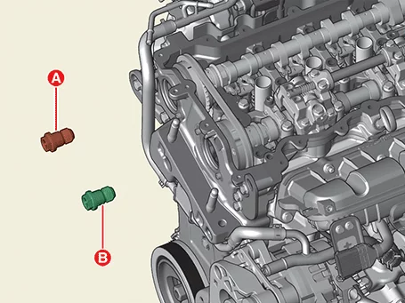
|
When removing the CVVT assembly bolt, hold the camshaft (A) with a wrench to
prevent the camshaft
from rotating.
|
|
| 16.
|
Remove the exhaust camshaft (A).
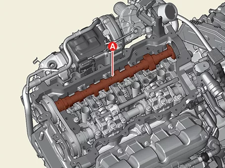
|
| 17.
|
Remove the exhaust CVVT(A) from the timing chain.
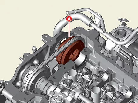
|
| 18.
|
Remove the intake CVVT (A) from the timing chain.
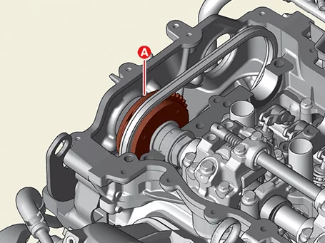
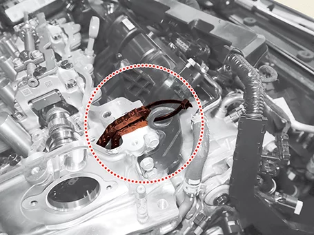
|
After removing the intake and exhaust CVVT and camshaft, fix the timing chain
well so that it
does not fall off.
|
|
CVVT & Exhaust Camshaft Installation
|
•
|
This video was created using 3D graphics to help understand the vehicle
maintenance manual.
|
|
•
|
There may be some differences from actual vehicles.
|
|
•
|
The location and repair procedures of the parts may vary depending on vehicle
model, model year,
region, and specifications.
|
|
•
|
Check the KDS Guide for detailed information on how to use the KDS.
|
|
•
|
Check the manual for detailed maintenance procedures.
|
|
•
|
Unauthorized reproduction, distribution, or sharing of this video is
prohibited.
|
|
CVVT & Exhaust Camshaft Installation
(Click to play)
Video: CVVT & Exhaust Camshaft
Installation
| Continuously Variable Valve Timing (CVVT) and exhaust
camshafts
|
| 1.
|
Install the intake CVVT (A).
|
| 2.
|
Install the intake OCV and center bolt (A).
|
Tightening torque :
Step 1 : 22.6 - 26.5 N·m (2.3 - 2.7 kgf·m, 16.6 - 19.5 lb·ft)
Step 2 : 32 - 36°
|
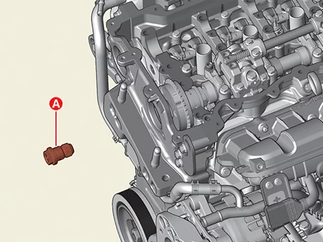
|
When installing the CVVT assembly bolt, fix the camshaft (A) part with a
wrench.
|
|
| 3.
|
Seat the exhaust CVVT(A).
|
| 4.
|
Install the exhaust camshaft (A).
|
Check if the swing arm is installed properly.
|
|
| 5.
|
Install the exhaust OCV and center bolt (A).
|
Tightening torque :
Step 1 : 22.6 - 26.5 N·m (2.3 - 2.7 kgf·m, 16.6 - 19.5 lb·ft)
Step 2 : 32 - 36°
|
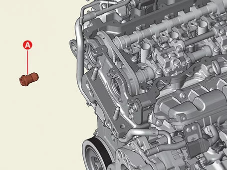
|
When installing the CVVT assembly bolt, fix the (A) part of the camshaft with a
ratchet.
|
|
| 6.
|
Install the camshaft front bearing cap (A) and camshaft bearing cap (B) and then tighten the
bolts.
| (1)
|
Install the camshaft front bearing cap and camshaft bearing cap bolts from the
rear of the engine
to the front according in the order of illustration below.
|
Tightening torque
A : 4.9 - 6.9 N·m (0.5
- 0.7 kgf·m, 3.6 - 5.1
lb·ft, 43.4 - 60.8 lb·in)
|
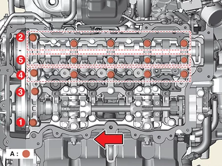
|
| (2)
|
Install the camshaft front bearing cap and camshaft bearing cap bolts from the
rear of the engine
to the front according in the order of illustration below.
|
Tightening torque
A : 9.8 - 11.8 N·m (1.0
- 1.2 kgf·m, 7.2 - 8.7
lb·ft)
|
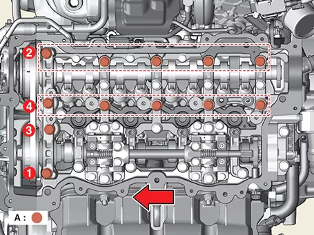
|
| (3)
|
Install the camshaft front bearing cap and camshaft bearing cap bolts from the
rear of the engine
to the front according in the order of illustration below.
|
Tightening torque
A : 18.6 - 22.6 N·m (1.9
- 2.3 kgf·m, 13.7 - 16.6
lb·ft)
B(New) : 11.8 - 13.7 N·m
(1.2 - 1.4 kgf·m, 8.7 -
10.1 lb·ft)
B(Old) : 9.8 - 11.8 N·m
(1.0 - 1.2 kgf·m, 7.2 -
8.7 lb·ft)
|
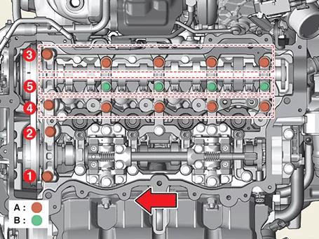
|
|
| 7.
|
Remove the awl (A) that is holding the timing chain tensioner.
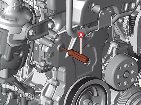
|
| 8.
|
Install in reverse order of removal.
|
Install to the specified torque.
|
|
CVVT & Exhaust Camshaft Inspection
|
•
|
This video was created using 3D graphics to help understand the vehicle
maintenance manual.
|
|
•
|
There may be some differences from actual vehicles.
|
|
•
|
The location and repair procedures of the parts may vary depending on vehicle
model, model year,
region, and specifications.
|
|
•
|
Check the KDS Guide for detailed information on how to use the KDS.
|
|
•
|
Check the manual for detailed maintenance procedures.
|
|
•
|
Unauthorized reproduction, distribution, or sharing of this video is
prohibited.
|
|
CVVT & Exhaust Camshaft Inspection
(Click to play)
Video: CVVT & Exhaust Camshaft
Inspection
Camshaft
| 1.
|
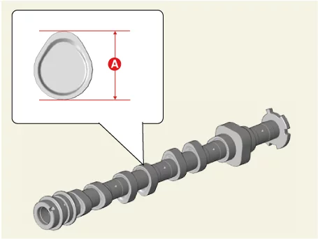
Check cam height (A).
If the cam lobe height is less than specification, replace the camshaft.
|
Cam height
Exhaust : 37.44 mm (1.474 in.)
|
|
| 2.
|
Inspect the camshaft journal clearance.
| (1)
|
Clean the bearing caps and camshaft journals.
|
| (2)
|
Place the camshafts on the cam carrier.
|
| (3)
|
Place a plastic gauge for each journal on the camshaft.
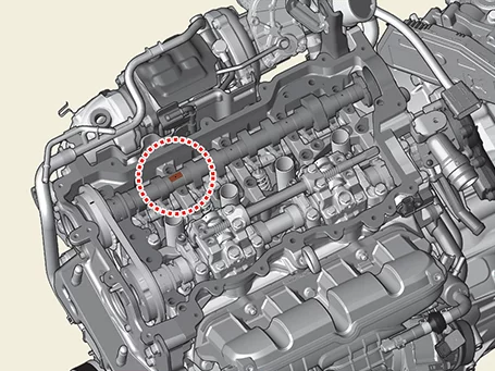
|
| (4)
|
Install the camshaft front bearing cap (A) and camshaft bearing cap (B) and
then tighten the
bolts.
|
Tightening torque :
A(M8) step 1 : 9.8 - 11.8 N·m (1.0 - 1.2 kgf·m, 7.2 - 8.7
lb·ft)
A(M8) step 2 : 18.6 - 22.6 N·m (1.9 - 2.3 kgf·m, 13.7 - 16.6
lb·ft)
B(M6) step 1 : 4.9 - 6.9 N·m (0.5 - 0.7 kgf·m, 3.6 - 5.1 lb·ft)
B(M6) step 2 : 11.8 - 13.7 N·m (1.2 - 1.4 kgf·m, 8.7 - 10.1
lb·ft)
B(M8) step 1 : 9.8 - 11.8 N·m (1.0 - 1.2 kgf·m, 7.2 - 8.7
lb·ft)
B(M8) step 2 : 18.6 - 22.6 N·m (1.9 - 2.3 kgf·m, 13.7 - 16.6
lb·ft)
|
| (1) |
Install the camshaft front bearing cap and camshaft bearing cap
bolts from the rear of
the engine to the front according to the sequence in the figure
below.
|
Tightening
torque
A : 4.9
- 6.9 N·m (0.5 - 0.7 kgf·m, 3.6 -
5.1 lb·ft, 43.4 - 60.8 lb·in)
|
|
| (2) |
Install the camshaft front bearing cap and camshaft bearing cap
bolts from the rear of
the engine to the front according to the sequence in the figure
below.
|
Tightening
torque
A : 9.8
- 11.8 N·m (1.0 - 1.2 kgf·m, 7.2
- 8.7 lb·ft)
|
|
| (3) |
Install the camshaft front bearing cap and camshaft bearing cap
bolts from the rear of
the engine to the front according to the sequence in the figure
below.
|
Tightening
torque
A : 18.6
- 22.6 N·m (1.9 - 2.3 kgf·m, 13.7
- 16.6 lb·ft)
B(New) :
11.8 - 13.7 N·m (1.2 - 1.4 kgf·m,
8.7 - 10.1 lb·ft)
B(Old) :
9.8 - 11.8 N·m (1.0 - 1.2 kgf·m,
7.2 - 8.7 lb·ft)
|
|
|
| (5)
|
Remove the camshaft bearing cap.
|
| (6)
|
Measure the plastic gauge at its widest point.
If the oil clearance exceeds the specified value, replace the camshaft. If
necessary, replace the
bearing cap and cam carrier.
|
Camshaft bearing cap oil
clearance
Specifications
No.1 journal : 0.040 -
0.071 mm (0.0016 - 0.0028
in.)
No.2, 3, 4, 5 journal :
0.035 - 0.066 mm (0.0014 -
0.0026 in.)
|
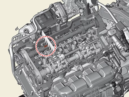
|
| (7)
|
Remove the plastic gauge completely.
|
|
| 3.
|
Inspect the camshaft end play.
| (1)
|
Install the camshaft.
|
| (2)
|
Use a dial gauge to measure the end play while moving the camshaft in the axial
direction.
|
Camshaft end play
Specified value : 0.10 -
0.19 mm (0.0039 - 0.0075
in.)
|
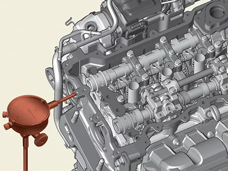
If the end play exceeds the limit, replace the camshaft. If necessary, replace
the cam carrier.
|
|
CVVD & Intake camshaft assembly Description and Operation
The Continuously Variable Valve Duration (CVVD) system adjusts the optimal opening/closing timing by changing
the
valve opening cycle depending on the system operating mode.
The CVVD system consists of a camshaft (A), a CVVD mechanism (B) and a CVVD actuator (C).
The valve opening time is proportional to the number of rotations of the control shaft.
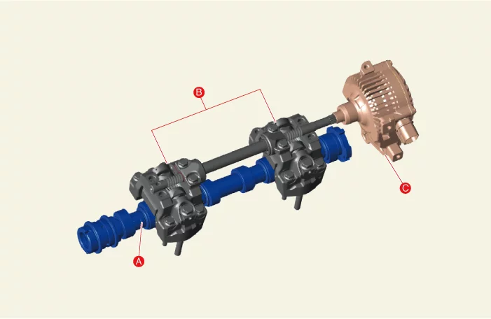
[CVVD system operating mode]
Optimal valve timing according to engine load-specific conditions.
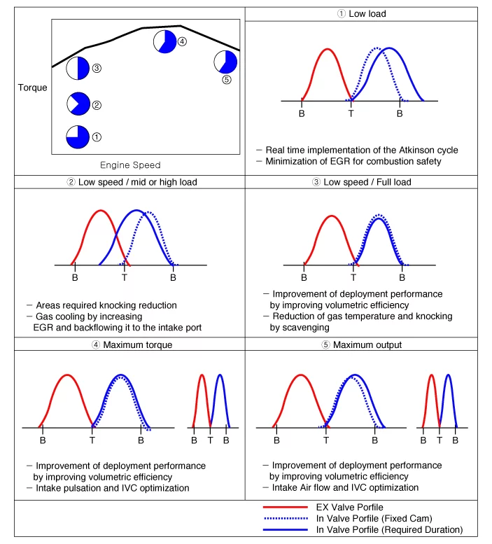
CVVD & Intake camshaft assembly Removal
|
•
|
This video was created using 3D graphics to help understand the vehicle
maintenance manual.
|
|
•
|
There may be some differences from actual vehicles.
|
|
•
|
The location and repair procedures of the parts may vary depending on vehicle
model, model year,
region, and specifications.
|
|
•
|
Check the KDS Guide for detailed information on how to use the KDS.
|
|
•
|
Check the manual for detailed maintenance procedures.
|
|
•
|
Unauthorized reproduction, distribution, or sharing of this video is
prohibited.
|
|
CVVD & Intake Camshaft Assembly Removal
(Click to play)
Video: CVVD & Intake Camshaft Assembly
Removal
Tool Name / Number
|
Illustration
|
Description
|
CVVD fixing jig
0K240-P4100
|
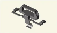
|
For CVVD assembly removal and install
|
|
Do not rotate the control shaft.
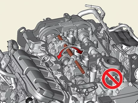
|
| 1.
|
Turn the crankshaft damper pulley clockwise to bring the piston of cylinder 1 to compression
top dead
center so that the timing mark on the timing chain cover matches the groove on the damper
pulley.
|
| 2.
|
Remove the CVVD actuator.
(Refer to Engine Control / Fuel System - "CVVD
Actuator")
|
| 3.
|
Remove the cylinder head cover.
(Refer to Cylinder Head Assembly - "Cylinder Head
Cover")
|
| 4.
|
Remove the intake and exhaust Variable Force Solenoid (VFS) valves.
(Refer to Engine Control / Fuel System - "Variable Force
Solenoid
(VFS)")
|
| 5.
|
Rotate so that the TDC marks on the intake CVVT sprocket and exhaust CVVT sprocket are aligned
with the
top surface of the cylinder head so that cylinder 1 is at compression top dead center.
|
| 6.
|
Permanent ink markings on chain links matching intake and exhaust continuously variable valve
(CVVT)
timing markings.
[Intake CVVD]
[Exhaust CVVT]
|
| 7.
|
Remove the cam to cam guide (A), after removing the bolt.
|
Tightening torque :
9.8 - 11.8 N·m (1.0 - 1.2 kgf·m, 7.2 - 8.7 lb·ft)
|
|
| 8.
|
Remove the service hole cover bolt (A).
|
Tightening torque :
27.5 - 30.4 N·m (2.8 - 3.1 kgf·m, 20.3 - 22.4 lb·ft)
|
|
| 9.
|
Using a fine awl, etc. (A), lower the ratchet plate (B) of the timing chain tensioner downward
to release
the lock.
|
When releasing the timing chain tensioner lock, lift the timing chain in the
direction of the
arrow.
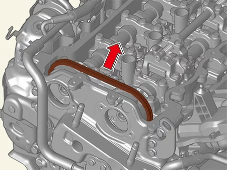
|
|
| 10.
|
Remove the exhaust OCV and center bolt (A) and intake OCV and center bolt (B).
|
Tightening torque :
A step 1 : 22.6 - 26.5 N·m (2.3 - 2.7 kgf·m, 16.6 - 19.5 lb·ft)
A step 2 : 32 - 36°
B step 1 : 22.6 - 26.5 N·m (2.3 - 2.7 kgf·m, 16.6 - 19.5 lb·ft)
B step 2 : 32 - 36°
|
|
When removing the CVVT assembly bolt, hold the camshaft (A) with a wrench to
prevent the camshaft
from rotating.
|
|
| 11.
|
Remove the high pressure fuel pump brackets (A), after removing the bolts.
|
Tightening torque :
12.7 - 14.7 N·m (1.3 - 1.5 kgf·m, 9.4 - 10.8 lb·ft)
|
|
| 12.
|
Remove the camshaft front bearing cap bolt and camshaft bearing cap bolt (A).
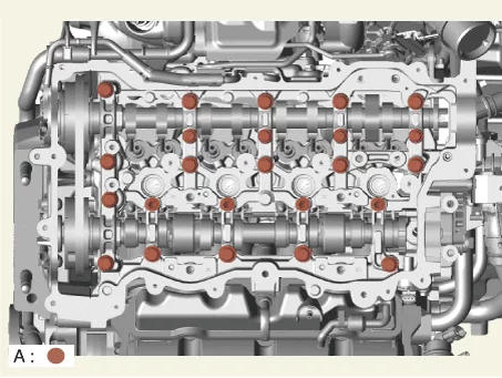
|
| 13.
|
Remove the camshaft front bearing cap (A) and camshaft bearing cap (B).
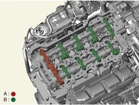
|
| 14.
|
Sperate the CVVT from the intake and exhaust camshafts by pulling in the direction of the
arrow.
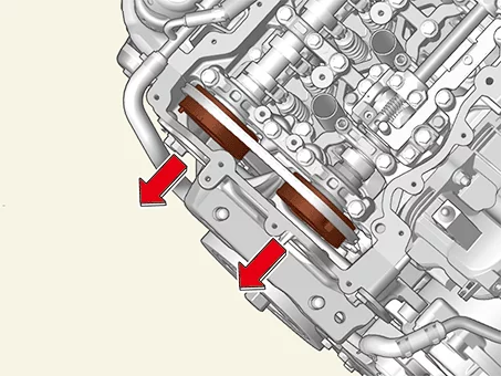
|
| 15.
|
Remove the continuously variable valve duration (CVVD) assembly.
| (1)
|
Install the SST (0K240 - P4100) to camshaft and CVVD assembly.
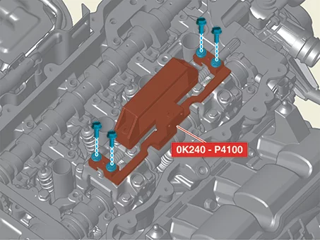
|
•
|
When installing the SST (0K240 - P4100),
tighten it by hand using the cylinder
head cover bolts.
|
|
•
|
Do not turn the control shaft.
|
|
|
| (2)
|
Remove the CVVD assembly bolt (A).
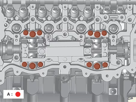
|
| (3)
|
Remove the CVVD assembly (A).
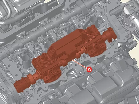
|
•
|
When moving the CVVD, always hold only the
handle (A) of the SST (0K240 - P4100).
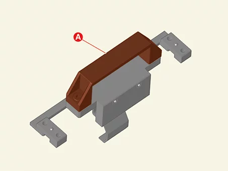
|
|
•
|
Remove the CVVD after slightly lifting the
front part of the camshaft.
|
|
•
|
After removing the CVVD assembly, make sure
that the hydraulic valve clearance
adjustment device (HLA) and swing arm do not
come off.
|
|
•
|
Check the CVVD assembly for damage.
|
|
•
|
Do not disassemble the CVVD assembly.
|
|
•
|
Do not rotate the control shaft.
|
|
|
|
CVVD & Intake camshaft assembly Installation
|
•
|
This video was created using 3D graphics to help understand the vehicle
maintenance manual.
|
|
•
|
There may be some differences from actual vehicles.
|
|
•
|
The location and repair procedures of the parts may vary depending on vehicle
model, model year,
region, and specifications.
|
|
•
|
Check the KDS Guide for detailed information on how to use the KDS.
|
|
•
|
Check the manual for detailed maintenance procedures.
|
|
•
|
Unauthorized reproduction, distribution, or sharing of this video is
prohibited.
|
|
CVVD & Intake Camshaft Assembly Installation
(Click to play)
Video: CVVD & Intake Camshaft Assembly
Installation
Tool Name / Number
|
Illustration
|
Description
|
CVVD fixing jig
0K240 - P4100
|
|
Removal and installation of CVVD assembly
|
|
•
|
Do not turn the control shaft.
|
|
•
|
[When replacing a new one]
|
| 1) |
Remove the jig (A).
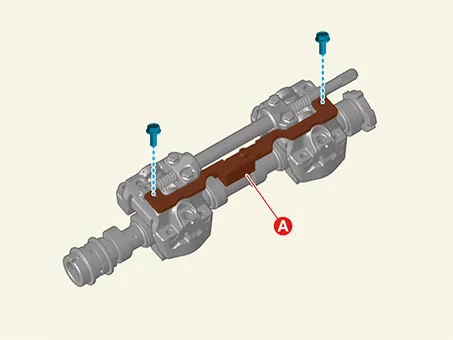
- When removing the jig, work within the frame provided.
|
| 2) |
Install the SST (0K240 - P4100).
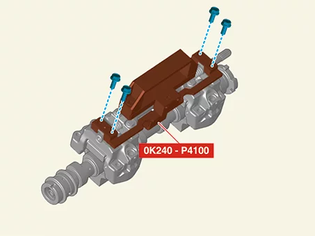
- When installing the SST (0K240 - P4100), work within the frame provided.
- When installing the SST (0K240 - P4100), tighten it by hand using the
cylinder head cover
bolts.
|
|
| 1.
|
Install the CVVD assembly.
| (1)
|
Install the CVVD assembly (A).
|
•
|
When moving the CVVD, always hold only the
handle (A) of the SST (0K240 - P4100).
|
|
•
|
When installing the CVVD assembly, spray the
engine oil to the camshaft journal
installing part of the cam carrier.
|
|
•
|
The amount of application should be enough to
flow down both the front and back
sides when it is applied to the center.
|
|
|
| (2)
|
Check that the camshaft groove is at the 12 o'clock position.
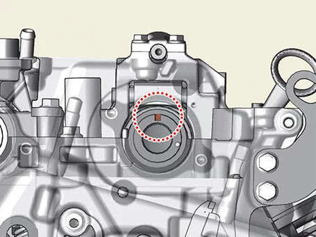
|
| (3)
|
Tighten the CVVD assembly M6 bolts (A) according to the sequence in the figure
below.
|
Tightening torque
Step 1 : 4.9 - 6.9 N·m (0.5 - 0.7 kgf·m, 3.6 - 5.1 lb·ft, 43.4
- 60.8 lb·in)
Step 2 : 9.8 - 11.8 N·m (1.0 - 1.2 kgf·m, 7.2 - 8.7 lb·ft)
|
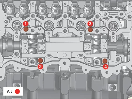
|
| (4)
|
Remove the CVVD fixing jig (0K240 - P4100).
|
•
|
When removing the CVVD fixture, be sure to
securely tighten the M6 bolts.
|
|
•
|
Do not turn the control shaft.
|
|
|
| (5)
|
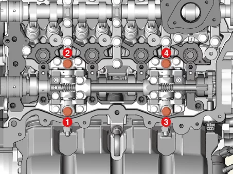
Tighten the CVVD assembly M8 bolts according to the sequence in the figure
below.
|
Tightening torque :
9.8 - 11.8 N·m (1.0 - 1.2 kgf·m, 7.2 - 8.7 lb·ft)
|
|
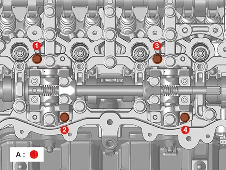
| (6)
|
Remove the CVVD assembly M6 bolts (A) according to the sequence in the figure
below.
|
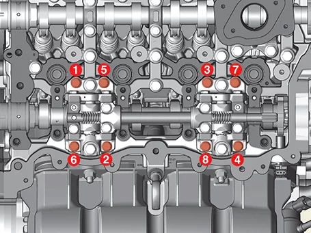
| (7)
|
Tighten the CVVD assembly M6 bolts (A) according to the sequence in the figure
below.
|
Tightening torque :
4.9 - 6.9 N·m (0.5 - 0.7 kgf·m, 3.6 - 5.1 lb·ft, 43.4 - 60.8
lb·in)
|
|
| (8)
|
Tighten the CVVD assembly M8 bolts according to the sequence in the figure
below.
|
Tightening torque :
18.6 - 22.6 N·m (1.9 - 2.3 kgf·m, 13.7 - 16.6 lb·ft)
|
|
| (9)
|
Tighten the CVVD assembly M6 bolts (A) according to the sequence in the figure
below.
|
Tightening torque :
9.8 - 11.8 N·m (1.0 - 1.2 kgf·m, 7.2 - 8.7 lb·ft)
|
|
|
| 2.
|
Install the Intake CVVD (A).
|
| 3.
|
Install the intake OCV and center bolt (A).
|
Tightening torque :
Step 1 : 22.6 - 26.5 N·m (2.3 - 2.7 kgf·m, 16.6 - 19.5 lb·ft)
Step 2 : 32 - 36°
|
|
When installing the CVVT assembly bolt, fix the camshaft A part with a wrench.
|
|
| 4.
|
Seat the exhaust CVVT (A).
|
| 5.
|
Install the exhaust OCV and center bolt (A).
|
Tightening torque :
Step 1 : 22.6 - 26.5 N·m (2.3 - 2.7 kgf·m, 16.6 - 19.5 lb·ft)
Step 2 : 32 - 36°
|
|
When installing the CVVT assembly bolt, fix the A part of the camshaft with a
ratchet.
|
|
| 6.
|
Install the camshaft front bearing cap (A) and camshaft bearing cap (B) in the order of
illustration
below.
|
•
|
When the camshaft front bearing cap and camshaft bearing cap
mounting bolts and bolt
holes are sufficiently covered with engine oil, tighten to the
lower limit of the tightening
torque.
|
|
•
|
After applying engine oil to the upper part of the intake
camshaft journal, install the
camshaft front bearing cap and camshaft bearing cap. When
applied to the center, the amount
of application is applied so that it flows down front and back.
|
|
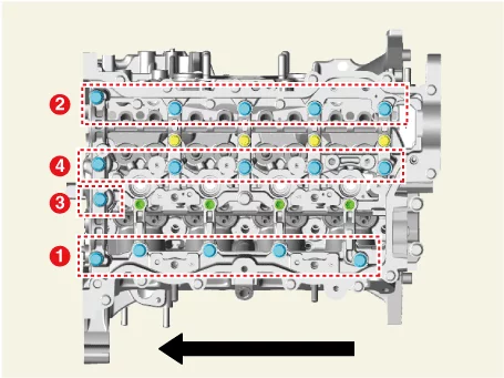
| (1)
|
Follow the procedure in the order of illustration below to install the camshaft
front bearing cap
and camshaft bearing cap mounting bolts from the rear of the engine to the
front.
|
Tightening torque :
4.9 - 6.9 N·m (0.5 - 0.7 kgf·m, 3.6 - 5.1 lb·ft)
|
|
| (2)
|
Follow the procedure in the order of illustration below to install the camshaft
bearing cap
mounting bolts from the rear of the engine to the front.
|
Tightening torque :
4.9 - 6.9 N·m (0.5 - 0.7 kgf·m, 3.6 - 5.1 lb·ft)
|
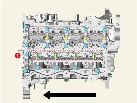
|
| (3)
|
Follow the procedure in the order of illustration below to install the camshaft
bearing cap
mounting bolts from the rear of the engine to the front.
|
Tightening torque :
4.9 - 6.9 N·m (0.5 - 0.7 kgf·m, 3.6 - 5.1 lb·ft)
|
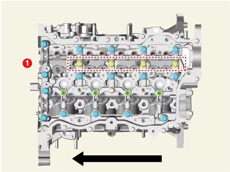
|
| (4)
|
Follow the procedure in the order of illustration below to install the camshaft
front bearing cap
and camshaft bearing cap mounting bolts from the rear of the engine to the
front.
|
Tightening torque :
9.8 - 11.8 N·m (1.0 - 1.2 kgf·m, 7.2 - 8.7 lb·ft)
|
|
| (5)
|
Follow the procedure in the order of illustration below to install the camshaft
front bearing cap
and camshaft bearing cap mounting bolts from the rear of the engine to the
front.
|
Tightening torque :
18.6 - 22.6 N·m (1.9 - 2.3 kgf·m, 13.7 - 16.6 lb·ft)
|
|
| (6)
|
Follow the procedure in the order of illustration below to install the camshaft
bearing cap
mounting bolts from the rear of the engine to the front.
|
Tightening torque :
9.8 - 11.8 N·m (1.0 - 1.2 kgf·m, 7.2 - 8.7 lb·ft)
|
|
| (7)
|
Follow the procedure in the order of illustration below to install the camshaft
bearing cap
mounting bolts from the rear of the engine to the front.
|
Tightening torque :
9.8 - 11.8 N·m (1.0 - 1.2 kgf·m, 7.2 - 8.7 lb·ft)
|
|
|
| 7.
|
Install the cylinder head cover.
(Refer to Cylinder Head Assembly - "Cylinder Head
Cover")
|
| 9.
|
Implement CVVD Learning of KDS add-on.
(S/W Management → Engine Control → CVVD Intake Adaptation)
|
Refer to the KDS screen for operating conditions and details
|
|
CVVD & Intake camshaft assembly Inspection
|
•
|
This video was created using 3D graphics to help understand the vehicle
maintenance manual.
|
|
•
|
There may be some differences from actual vehicles.
|
|
•
|
The location and repair procedures of the parts may vary depending on vehicle
model, model year,
region, and specifications.
|
|
•
|
Check the KDS Guide for detailed information on how to use the KDS.
|
|
•
|
Check the manual for detailed maintenance procedures.
|
|
•
|
Unauthorized reproduction, distribution, or sharing of this video is
prohibited.
|
|
CVVD & Intake camshaft assembly Inspection
(Click to play)
Video: CVVD & Intake camshaft assembly
Inspection
Camshaft
| 1.
|
Check cam height.
If the cam lobe height is less than specification, replace the camshaft.
|
Cam height
Intake : 37.33 mm (1.4697 in.)
|
|
| 2.
|
Inspect the camshaft journal clearance.
| (1)
|
Clean the bearing caps and camshaft journals.
|
| (2)
|
Place the camshafts on the cam carrier.
|
| (3)
|
Place a plastic gauge for each journal on the camshaft.
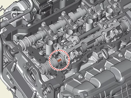
|
| (4)
|
Install the camshaft front bearing cap (A) and camshaft bearing cap (B) in the
order of
illustration below.
|
•
|
When the camshaft front bearing cap and
camshaft bearing cap mounting bolts and
bolt holes are sufficiently covered with engine
oil, tighten to the lower limit of
the tightening torque.
|
|
•
|
After applying engine oil to the upper part of
the intake camshaft journal,
install the camshaft front bearing cap and
camshaft bearing cap. When applied to the
center, the amount of application is applied so
that it flows down front and back.
|
|
| (1) |
Follow the procedure in the order of illustration below to
install the camshaft front
bearing cap and camshaft bearing cap mounting bolts from the
rear of the engine to the
front.
|
Tightening
torque :
4.9 - 6.9 N·m (0.5 - 0.7 kgf·m, 3.6 - 5.1
lb·ft)
|
|
| (2) |
Follow the procedure in the order of illustration below to
install the camshaft bearing
cap mounting bolts from the rear of the engine to the front.
|
Tightening
torque :
4.9 - 6.9 N·m (0.5 - 0.7 kgf·m, 3.6 - 5.1
lb·ft)
|
|
| (3) |
Follow the procedure in the order of illustration below to
install the camshaft bearing
cap mounting bolts from the rear of the engine to the front.
|
Tightening
torque :
4.9 - 6.9 N·m (0.5 - 0.7 kgf·m, 3.6 - 5.1
lb·ft)
|
|
| (4) |
Follow the procedure in the order of illustration below to
install the camshaft front
bearing cap and camshaft bearing cap mounting bolts from the
rear of the engine to the
front.
|
Tightening
torque :
9.8 - 11.8 N·m (1.0 - 1.2 kgf·m, 7.2 - 8.7
lb·ft)
|
|
| (5) |
Follow the procedure in the order of illustration below to
install the camshaft front
bearing cap and camshaft bearing cap mounting bolts from the
rear of the engine to the
front.
|
Tightening
torque :
18.6 - 22.6 N·m (1.9 - 2.3 kgf·m, 13.7 - 16.6
lb·ft)
|
|
| (6) |
Follow the procedure in the order of illustration below to
install the camshaft bearing
cap mounting bolts from the rear of the engine to the front.
|
Tightening
torque :
9.8 - 11.8 N·m (1.0 - 1.2 kgf·m, 7.2 - 8.7
lb·ft)
|
|
| (7) |
Follow the procedure in the order of illustration below to
install the camshaft bearing
cap mounting bolts from the rear of the engine to the front.
|
Tightening
torque :
9.8 - 11.8 N·m (1.0 - 1.2 kgf·m, 7.2 - 8.7
lb·ft)
|
|
|
| (5)
|
Remove the camshaft bearing cap.
|
| (6)
|
Measure the plastic gauge at its widest point.
If the oil clearance exceeds the specified value, replace the camshaft. If
necessary, replace the
bearing cap and cam carrier.
|
Camshaft bearing cap oil
clearance
Specifications
No.1 journal : 0.040 -
0.071 mm (0.0016 - 0.0028
in.)
No.2, 3, 4, 5 journal :
0.035 - 0.066 mm (0.0014 -
0.0026 in.)
|
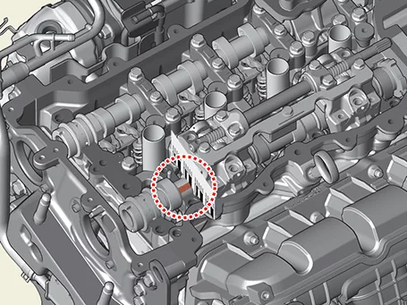
|
| (7)
|
Remove the plastic gauge completely.
|
|
Cylinder Head Removal
|
•
|
This video was created using 3D graphics to help understand the vehicle
maintenance manual.
|
|
•
|
There may be some differences from actual vehicles.
|
|
•
|
The location and repair procedures of the parts may vary depending on vehicle
model, model year,
region, and specifications.
|
|
•
|
Check the KDS Guide for detailed information on how to use the KDS.
|
|
•
|
Check the manual for detailed maintenance procedures.
|
|
•
|
Unauthorized reproduction, distribution, or sharing of this video is
prohibited.
|
|
Cylinder Head Removal
(Click to play)
Video: Cylinder Head Removal
|
In case of removing the high pressure fuel pump, high pressure fuel pipe, delivery pipe, and
injector,
there may be injury caused by leakage of the high pressure fuel. So don’t do any repair work
right after
engine stops.
|
|
•
|
Use a fender cover to protect the painted surface.
|
|
•
|
Wait for the engine to cool to room temperature before disassembling to prevent
damage to the
cylinder head.
|
|
•
|
Be careful not to damage the connector when disconnecting.
|
|
|
Mark all wiring and hoses to prevent incorrect connections.
|
| 1.
|
Release the residual pressure in fuel line.
(Refer to Fuel Delivery System - "Release Residual Pressure in
Fuel
Line")
|
| 2.
|
Disconnect the battery negative ( - ) terminal.
|
| 3.
|
Remove the engine cover.
(Refer to Engine and Transaxle Assembly - "Engine
Cover")
|
| 4.
|
Remove the air cleaner assembly.
(Refer to Intake and Exhaust System - "Air Cleaner")
|
| 5.
|
Remove the battery and battery tray.
(Refer to Engine Electrical System - "Battery")
|
| 6.
|
Remove the engine room under cover.
(Refer to Engine and Transaxle Assembly - "Engine Room Under
Cover")
|
| 7.
|
Drain engine oil.
(Refer to Lubrication System - "Engine Oil")
|
| 8.
|
Drain the coolant.
(Refer to Cooling System - "Coolant")
|
| 9.
|
Disconnect the brake vacuum hose (A) after releasing the clamp.
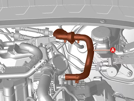
|
| 10.
|
Disconnect the fuel hose (B) and the Purge Control Solenoid Valve (PCSV) hose (A).
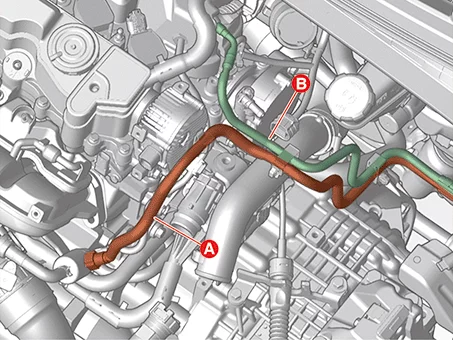
|
| 11.
|
Remove the intercooler inlet pipe bolt (A).
|
Tightening torque :
18.6 - 23.5 N·m (1.9 - 2.4 kgf·m, 13.7 - 17.4 lb·ft)
|
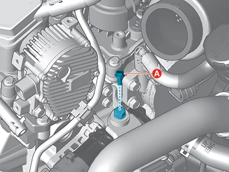
|
| 12.
|
Remove the intercooler inlet pipe (A) after releasing the clamp.
|
Tightening torque
Clamp bolt : 4.9 - 6.9 N·m (0.5 - 0.7
kgf·m, 3.6 - 5.1
lb·ft, 43.4 - 60.8 lb·in)
|
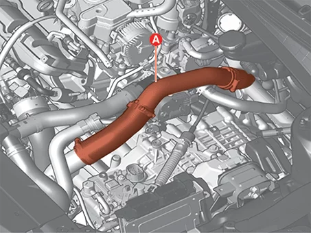
|
| 13.
|
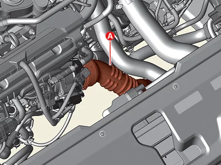
Remove the intercooler outlet hose after releasing the clamp.
|
| 14.
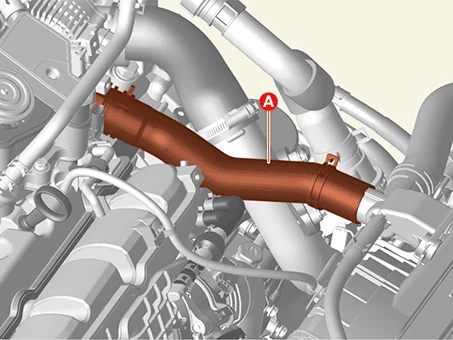
|
Separate the radiator upper hose (A) after releasing the clamp.
|
| 15.
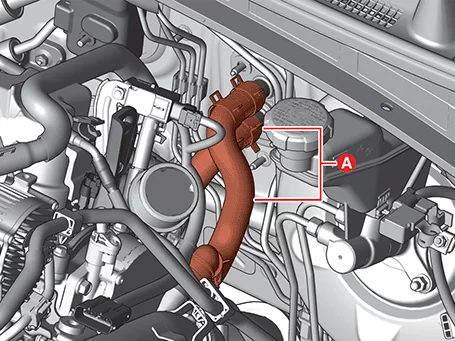
|
Release the clamp, and then disconnect the heater hose (A).
|
| 16.
|
Remove the cylinder head cover.
(Refer to Cylinder Head Assembly - "Cylinder Head
Cover")
|
| 17.
|
Remove the timing chain.
(Refer to Timing System - "Timing Chain Cover")
|
| 18.
|
Remove the Integrated Thermal Management Module (ITM).
(Refer to Cooling System - "Integrated Thermal Management
Module
(ITM)")
|
| 19.
|
Remove the vacuum pump.
(Refer to Brake System - "Vacuum Pump")
|
| 20.
|
Remove the intake manifold.
(Refer to Intake and Exhaust System - "Intake Manifold")
|
| 21.
|
Remove the turbo manifold.
(Refer to Intake and Exhaust System - "Turbo Manifold")
|
| 22.
|
Remove the delivery pipe.
(Refer to Engine Control / Fuel System - "Delivery
Pipe")
|
| 23.
|
Remove the spark plug.
(Refer to Engine Electrical System - "Spark Plug")
|
| 24.
|
Remove the CVVT and exhaust camshaft.
(Refer to Cylinder Head Assembly - "CVVT & Exhaust
Camshaft")
|
| 25.
|
Remove the CVVD and intake camshaft.
(Refer to Cylinder Head Assembly - "CVVD & Intake
Camshaft")
|
| 26.
|
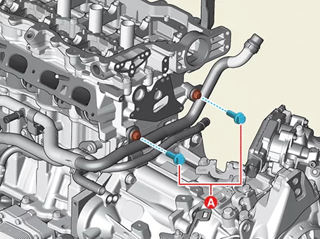
Remove the heater pipe bolts (A).
|
| 27.
|
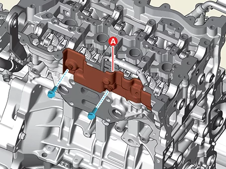
Remove the cylinder head cover heat protector (A) after removing the bolts.
|
| 28.
|
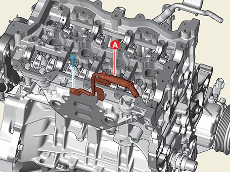
Remove the turbocharger water outlet hose and pipe (A) after removing the bolts.
|
| 29.
|
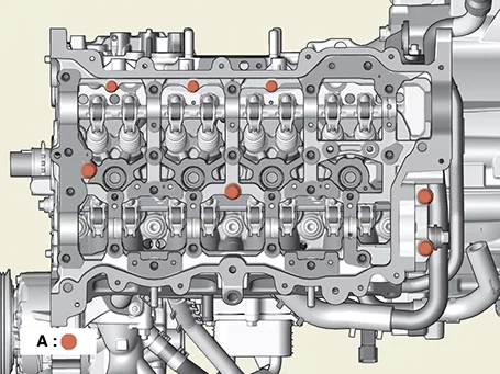
Remove the cam carrier mounting bolt (A).
|
| 30.
|
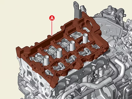
Remove the cam carrier (A).
|
| 31.
|
Remove the rear engine hanger after removing the nuts.
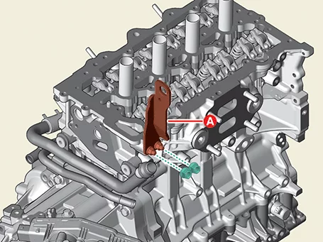
|
| 32.
|
Remove the Hydraulic Lash Adjuster (HLA) (A) and swing arm (B).
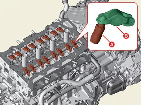
|
| 33.
|
Remove the cylinder head.
| (1)
|
Divide it into 2 - 3 times according to the orders below and remove the
cylinder head bolts.
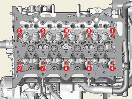
|
Deformation of the cylinder head may occur if the cylinder head
bolts are removed in the
wrong order.
|
|
| (2)
|
Lift the cylinder head (A) from the cylinder block and place it on the wooden
block.
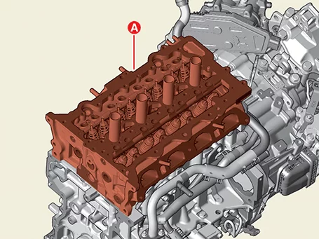
|
Be careful not to damage the contact surfaces of the cylinder
head and cylinder block.
|
|
| (3)
|
Remove the cylinder head gasket (A).
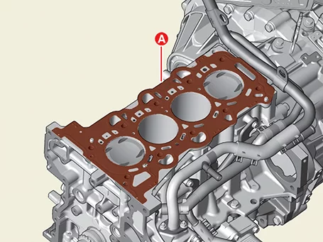
|
Do not reuse cylinder head gaskets.
|
|
|
Cylinder Head Inspection
|
•
|
This video was created using 3D graphics to help understand the vehicle
maintenance manual.
|
|
•
|
There may be some differences from actual vehicles.
|
|
•
|
The location and repair procedures of the parts may vary depending on vehicle
model, model year,
region, and specifications.
|
|
•
|
Check the KDS Guide for detailed information on how to use the KDS.
|
|
•
|
Check the manual for detailed maintenance procedures.
|
|
•
|
Unauthorized reproduction, distribution, or sharing of this video is
prohibited.
|
|
Cylinder Head Inspection
(Click to play)
Video: Cylinder Head Inspection
| 1.
|
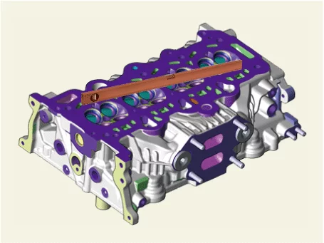
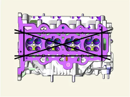
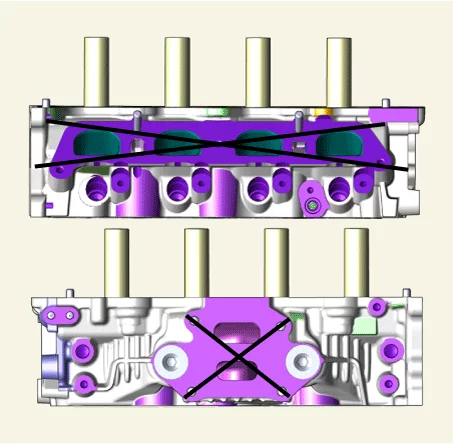
The flatness of the contact surface between the cylinder block and the manifold is measured
using a
precision square and gap gauge.
If the measured value is out of the specified value, replace the cylinder head.
|
Flatness of cylinder head gasket surface
Specified value :
Total : 0.05 mm (0.0020 in.) or less
100 mm x 100 mm (3.9370 in. x 3.9370 in.)
: 0.02 mm
(0.0008 in.) or less
Flatness of Manifold Mounting Surface
(Intake/Exhaust)
Specifications
Total : 0.10 mm (0.0039 in.) or less
|
|
| 2.
|
Inspect for cracks.
Check the combustion chamber, intake ports, exhaust ports and cylinder block surface for
cracks. If
cracked, replace the cylinder head.
|
| 1.
|
Inspect the valve stem and valve guides.
| (1)
|
Using a caliper gauge, measure the inner diameter of the valve guide.
|
Guide inner diameter
(intake/exhaust) : 5.505 -
5.517 mm (0.2167 - 0.2172 in.)
|
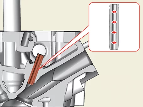
|
| (2)
|
Using a micrometer, measure the diameter of the valve stem.
|
Valve stem external
diameter
Intake : 5.465 - 5.480
mm (0.21516 - 0.21575 in.)
Exhaust : 5.458 - 5.470
mm (0.21488 - 0.21535 in.)
|
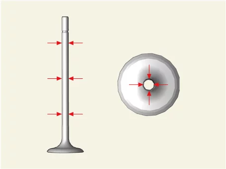
|
| (3)
|
Calculate the clearance between the valve guide and valve stem using measured
value.
|
Valve stem to guide clearance
Intake : 0.025 - 0.052
mm (0.00098 - 0.00204 in.)
Exhaust : 0.035 - 0.059
mm (0.00137 - 0.00232 in.)
|
If the clearance is over than limit value, replace the valve or cylinder head.
|
|
| 2.
|
Inspect the valve.
| (1)
|
Check the angle of the valve face (A).
|
Valve face angle :
45.25° - 45.75°
|
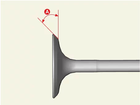
|
| (2)
|
Check the wear of the valve contact surface and replace the valve if wear is
excessive.
|
| (3)
|
Check the valve head margin thickness (A).
|
Valve head thickness
(Margin)
Intake : 0.70 mm (0.027
in.)
Exhaust : 0.91 mm (0.036
in.)
|
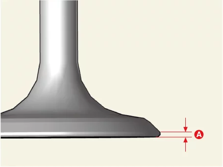
|
| (4)
|
Check the valve length (A).
|
Valve length
Intake : 112.84 mm
(4.4425 in.)
Exhaust : 123.18 mm
(4.8496 in.)
|
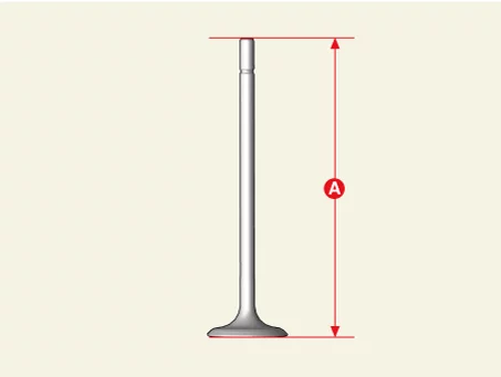
|
| (5)
|
Check valve stem tip for wear and replace the valve if wear is excessive.
|
|
| 3.
|
Inspect the valve seat.
| (1)
|
Check the valve seat for evidence of overheating and valve face contact
condition. Replace the
cylinder head if the valve seat is worn.
|
| (2)
|
Check the valve guide for wear. If the valve guide is worn, replace the
cylinder head.
|
|
| 4.
|
Inspect the valve spring.
| (1)
|
Using a steel square ruler, measure the out-of-square of the valve spring.
|
Squareness (Intake, Exhaust)
: 1.5° or less
|
|
| (2)
|
Using a vernier calipers, measure the free length (A) of the valve spring.
|
Valve spring :
Intake : 50.0 mm (1.968 in.)
Exhaust : 53.3 mm (2.098 in.)
|
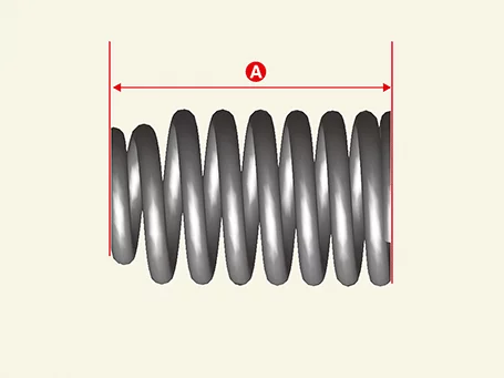
|
| (3)
|
Check the spring load using a valve spring tension tester.
|
Load
Intake
39.0mm (1.5354 in.) in height : 19.37 - 21.41 kg (190 - 210 N)
29.0 mm (1.1417 in.) in height : 44.28 - 47.49 kg (434.2 -
465.7 N)
Exhaust
39.0mm (1.5354 in.) in height : 24.5 - 260 kg (240 - 26.5 N)
29.0 mm (1.1417 in.) in height : 48.7 - 53.3 kg (477.5 - 522.5
N)
|
|
|
| HLA (Hydraulic Lash Adjuster) |
Hydraulic Lash Adjuster (HLA)
Hold the bottom (B) of the HLA filled with engine oil and press the cap (A) with your hand, and change the HLA
when the cap (A) moves.
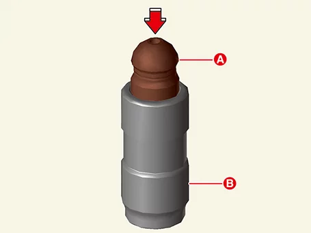
Problem
|
Suspected Cause
|
Correction
|
1. Noise occurs for several seconds when starting the engine
|
Normal condition
|
When the engine is stopped, the oil is leaking from the HLA, so the noise disappears when the oil
pressure
reaches a steady state
|
2. Continuous noise occurs when starting the engine after leaving it for 48 hours or more.
|
Air ingress due to oil leakage in high pressure chamber in HLA
|
When the engine is operated at 2,000-3,000 rpm, the noise disappears within 15
minutes
If not,
see Table 7
|
Do not run the engine above 3,000 rpm. HLA can be damaged.
|
|
Continuous noise when starting the engine immediately after disassembling and assembling the
cylinder head
|
Lack of oil in the cylinder head oil passage
|
Continuous noise when starting after excessive engine cranking
|
Air ingress due to oil leakage in high pressure chamber in HLA, lack of oil in the
cylinder head
oil passage
|
5. Continuous noise when starting the engine after replacing HLA
|
6. Continuous noise during idling immediately after high-speed driving
|
Inadequate amount of oil
|
Check the oil level and add or drain oil
|
Excessive air in the oil
|
Check the oil supply system
|
Oil deterioration
|
Change the oil
|
7. Continuous noise over 15 minutes
|
Low oil pressure
|
Check the oil pressure and the oil supply system of each part of the engine.
|
HLA defect
|
after removing the mounting cylinder head cover, check the HLA and replace the spongy HLA
|
* Spongy : Air flows into the high-pressure chamber inside the HLA, and the HLA is pressed even if it is
pressed
by hand.
Cylinder Head Disassembly
Tool Name / Number
|
Illustration
|
Description
|
Valve spring compressor
09222 - 3K000
Valve spring compressor adapter
09222 - 3K100
|
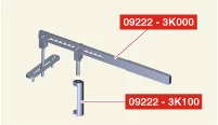
|
Removal and installation of intake and exhaust valves
|
| 1.
|
Remove the valve.
| (1)
|
Using the SST (09222 - 3K000, 09222 - 3K100), compress the valve spring and
remove the retainer
lock (A).
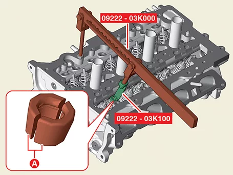
|
| (2)
|
Remove the retainer (A) and the valve spring (B).
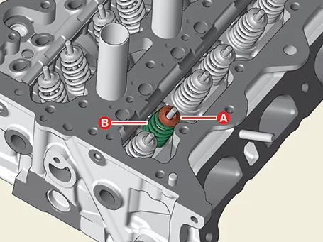
|
| (3)
|
Remove the valve (A).
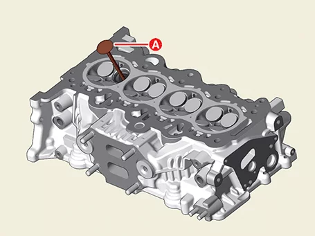
|
| (4)
|
Remove the valve stem seal (A).
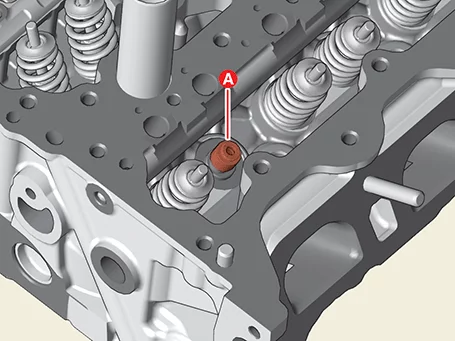
|
Do not reuse valve stem seal.
|
|
| (5)
|
Remove the valve spring seat (A).
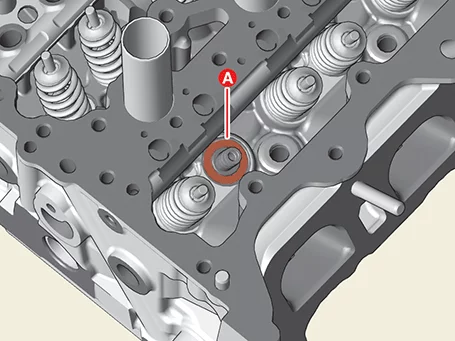
|
|
Cylinder Head Reassembly
Tool Name / Number
|
Illustration
|
Description
|
Valve spring compressor
09222 - 3K000
Valve spring compressor adapter
09222 - 3K100
|
|
Removal and installation of intake and exhaust valves
|
Valve stem seal installer
09222 - 2B100
|
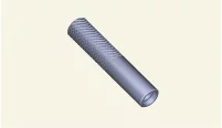
|
Used for installing valve stem seal
|
Steel ball installer
0K221 - 2M100
|
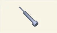
|
Used for installing steel ball
|
|
•
|
Thoroughly clean all parts to be assembled.
|
|
•
|
Before installing the parts, apply fresh engine oil to all sliding and rotating
surface.
|
|
| 1.
|
Install the valve.
| (1)
|
Install the valve spring seat (A).
|
| (2)
|
Install the valve stem seal, by using the SST (0K222 - 2E000).
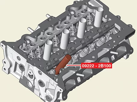
|
•
|
Do not reuse valve stem seal.
|
|
•
|
If the seal is installed incorrectly, oil may
leak through the valve guide, so be
careful.
|
|
|
| (3)
|
Insert the valve (A) into the valve guide.
|
Be careful not to change the positions of the intake and
exhaust valves.
|
|
| (4)
|
Install the valve spring (B) and retainer (A).
|
| (5)
|
Install the valve spring retainer lock (A), by using the SST (09222 - 3K000,
09222 - 3K100).
|
| (6)
|
Using the wooden handle of a hammer, tap the end of each valve stem two or
three times to ensure
the valve and retainer lock are seated correctly.
|
|
| 2.
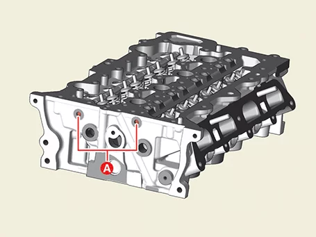
|
Check if the steel ball (A) is installed in the cylinder head when replacing the cylinder head.
|
| 3.
|
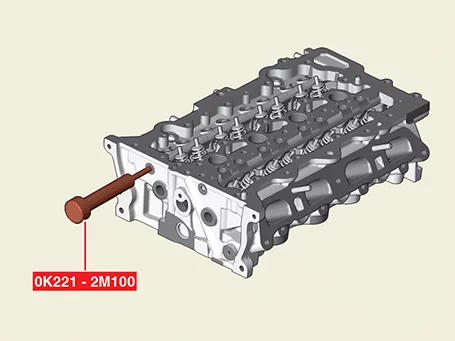
If steel ball not installed, be sure to install the steel ball.
| (1)
|
Stick the steel ball (A) to the SST (0K221 - 2M100).
|
| (2)
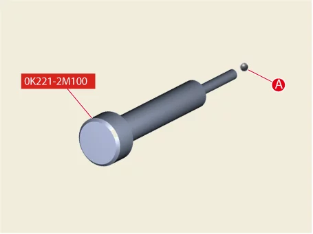
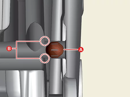
|
Use a special tool (0K221 - 2M100) and a hammer to mount the steel ball (A) to
the end (B).
|
|
Hydraulic Lash Adjuster (HLA) Removal and Installation
Tool Name / Number
|
Illustration
|
Description
|
HLA air bleed tool
0K246 - L8000
|
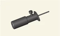
|
Used to air bleed HLA
|
| 1.
|
Remove the CVVT and Camshaft
(Refer to Cylinder Head Assembly - "CVVT &
Camshaft")
|
| 2.
|
Remove the Hydraulic Lash Adjuster (HLA) (A) and swing arm (B).
|
| 1.
|
Install in reverse order of removal.
|
•
|
Install to the specified torque.
|
|
•
|
Make sure the HLA is upright before assembly so that the engine
oil inside does not
overflow and dust and dirt are not attached.
|
|
•
|
Carefully insert the HLA into the cylinder head and take care
not to spill the oil. If
the engine oil overflows, perform air bleeding procedures below.
|
|
•
|
Immerse HLA in engine oil and use steel wire (A) to lightly
push down the ball (B) and
press the cap (C) of HLA 4-5 times at the same time. Be careful
not to press the steel wire
(A) too hard as the ball only weighs a few grams (g). If HLA is
installed with air mixed,
abnormal noise may occur.
|
|
•
|
How to bleed air
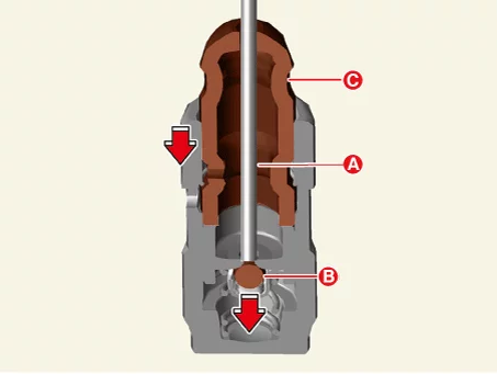
|
|
•
|
Perform the HLA air bleding.
1. Remove the cover (A) of the special tool (0K246 - L8000) and
loosen the bolt (B).
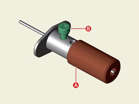
|
Do not remove the bolt (B).
|
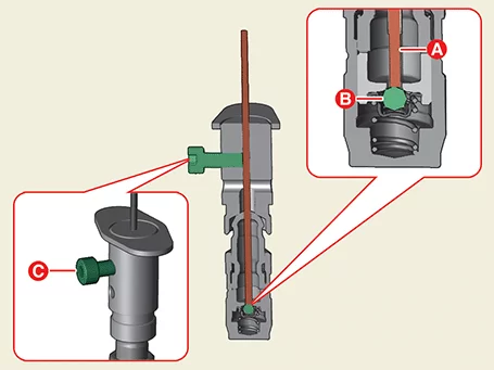
2. Tighten the bolt (C) with the special tool (0K246 - L8000)
with the pin (A) on the
ball (B).
Be careful not to push down the pin (A) too hard as the weight
of the ball is only a few
grams (g).
3. Hold HLA and special tool (0K246 - L8000) in oil with your
hand and press it 4-5 times
in the direction of the arrow.
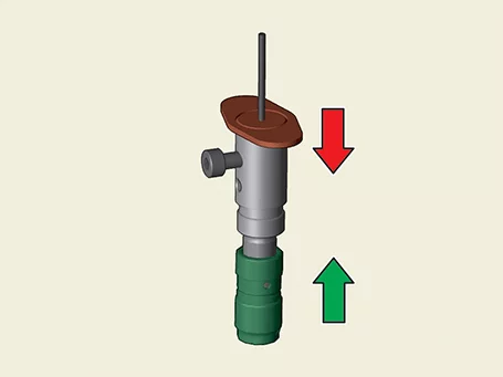
4. Hold the bottom (B) of the HLA filled with engine oil and
press the cap (A) with your
hands, repeating procedure 3 until the cap (A) is not pressed.
|
|
|
Other information:
Kia K4 (CL4) 2025-2026 Service Manual: Description and Operation
OBD-II review
1. Overview
The California Air Resources Board (CARB) began regulation of On Board Diagnostics (OBD) for vehicles sold in
California beginning with the 1988 model year. The first phase, OBD-I, required monitoring of the fuel metering
system, Exhaust Gas Recirculation (EGR) system and additional emission related components.
Kia K4 (CL4) 2025-2026 Service Manual: Highway Driving Assist settings
Driver Assistance
Driving Convenience
Highway Driving Assist
While the vehicle is powered ON, access your Kia K4 infotainment system and tap Setup > Vehicle > Driver Assistance > Driving Convenience to configure the customized options for each driver-assist function.