Contents:
Components and Components Location
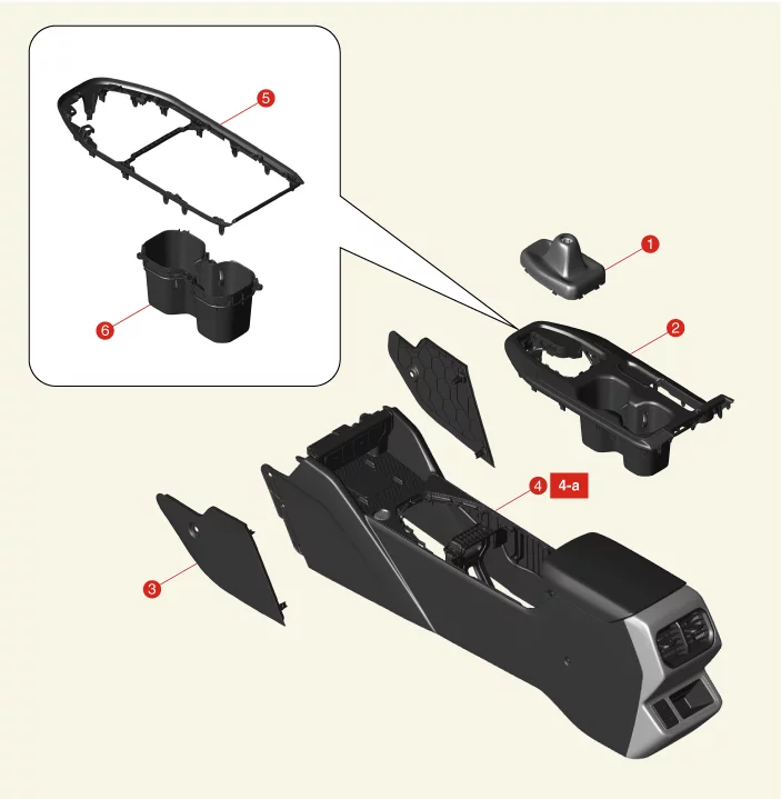
1. Gear Knob
2. Console Upper Cover
3.
Console
Side Cover
|
4. Console Assembly
5. Upper Cover
Garnish
6.
Cup Holder
|
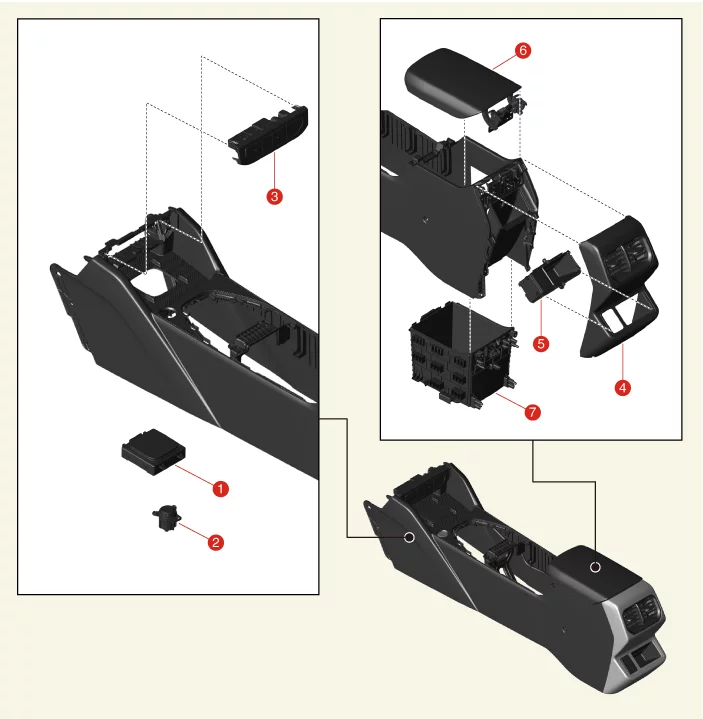
1. Wireless Power Charger (WPC)
2. Start /
Stop
Button (SSB)
3. Console Bezel
4. Rear Cover
|
5. Rear Cover Tray
6. Arm Rest
7.
Storage
Box
|
Floor Console Assembly Removal and Installation
|
•
|
This video was created using 3D graphics to help understand the vehicle
maintenance manual.
|
|
•
|
There may be some differences from actual vehicles.
|
|
•
|
The location and repair procedures of the parts may vary depending on vehicle
model, model year,
region, and specifications.
|
|
•
|
Check the KDS Guide for detailed information on how to use the KDS.
|
|
•
|
Check the manual for detailed maintenance procedures.
|
|
•
|
Unauthorized reproduction, distribution, or sharing of this video is
prohibited.
|
|
Floor Console Assembly Removal (Non-EPB Type)
(Click to play)

Video: Floor Console Assembly Removal (Non-EPB
Type)
Floor Console Assembly Removal (EPB Type)
(Click to play)
Video: Floor Console Assembly Removal (EPB
Type)
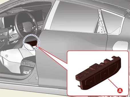
Floor Console Bezel
| 1.
|
Disconnect the battery negative (-) terminal.
|
| 2.
|
Remove the bezel (A).
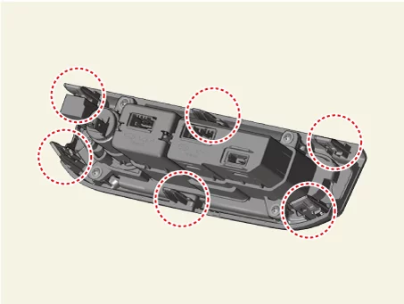
|
| 3.
|
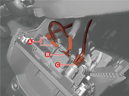
Disconnect the connectors.
A: Multimedia jack connectors
B: USB charger connector
C: Power outlet connector
|
Floor Console Assembly
| 1.
|
Remove the floor console bezel.
|
| 2.
|
Remove the floor console upper cover.
(Refer to Floor Console - "Floor Console Upper Cover")
|
| 3.
|
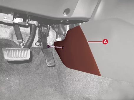
Remove the floor console side cover (A) after removing the fastener. [Both side]
|
| 4.
|
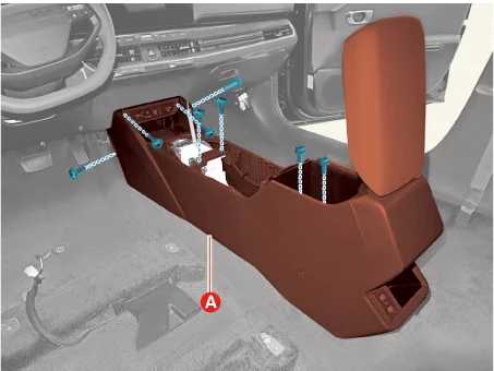
Remove the floor console assembly (A) after removing the bolts and screws.
|
Tightening torque:
7.8 - 9.8 N·m (0.8 - 1.0 kgf·m, 5.8 - 7.2 lb·ft)
|
|
| 5.
|
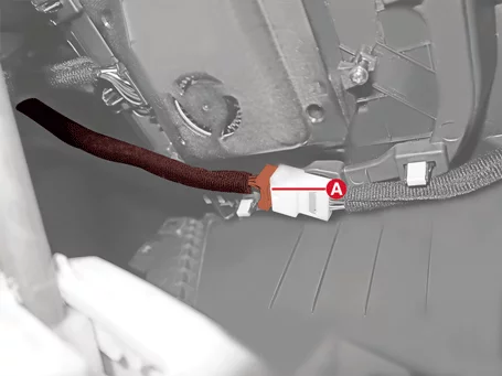
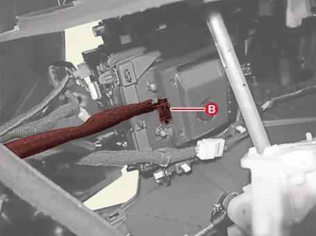
Disconnect the connectors.
A : Floor console extension connector
B : Wireless Power Charger (WPC) connector
|
| 1.
|
Install in the reverse order of removal.
|
Floor Console Assembly Disassembly and Reassembly
|
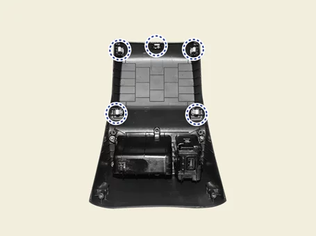
The indication below represents the location of a clip or fastener.

|
Wireless Power Charger (WPC)
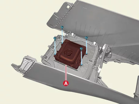
| 1.
|
Remove the unit (A) after removing the screws.
|
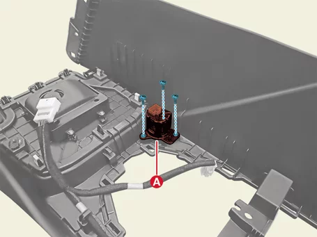
Start / Stop Button (SSB)
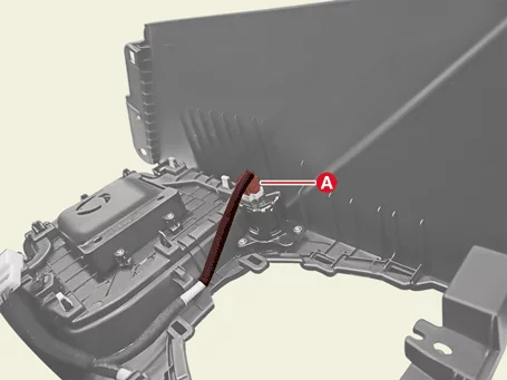
| 1.
|
Disconnect the SSB connector (A).
|
| 2.
|
Remove the SSB (A) after removing the screws.
|
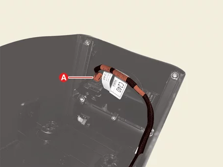
Rear Cover
| 1.
|
Disconnect the USB charger connector (A).
|
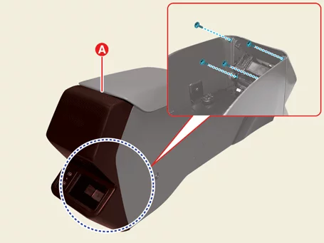
| 2.
|
Remove the cover (A) after removing the screws.
|
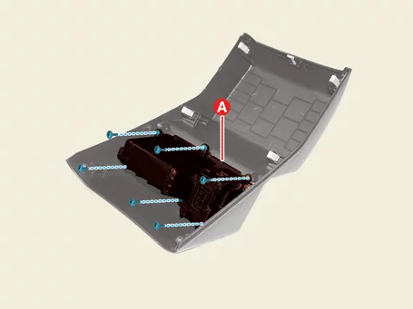
Rear Cover Tray
| 1.
|
Remove the rear cover.
|
| 2.
|
Remove the tray (A) after removing the screws.
|
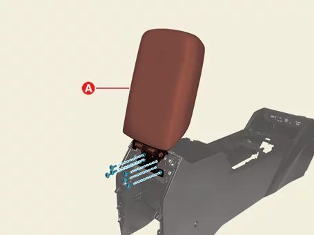
Arm Rest
| 1.
|
Remove the rear cover.
|
| 2.
|
Remove the arm rest (A) after removing the screws.
|
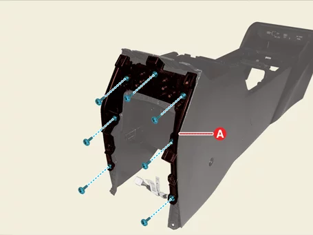
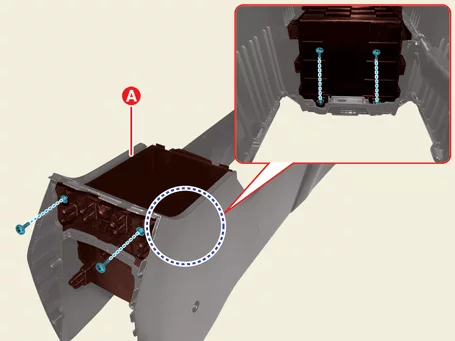
Storage Box
| 2.
|
Remove the rear garnish (A) after removing the screws.
|
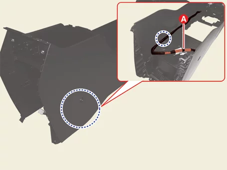
| 3.
|
Separate the USB charger connector wiring (A) after removing the fastener.
|
| 4.
|
Remove the storage box (A) after removing the screws.
|
| 1.
|
Reassemble in the reverse order of disassembly.
|
Floor Console Upper Cover Removal and Installation
|
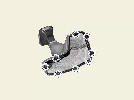
The indication below represents the location of a clip or fastener.
|
Automatic Transaxle Type
| 1.
|
Disconnect the battery negative (-) terminal.
|
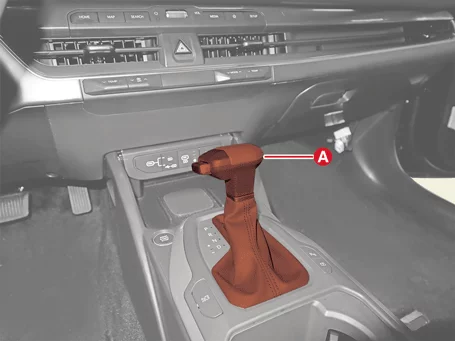
| 2.
|
Remove the gear knob (A).
|
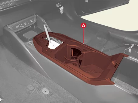
| 3.
|
Remove the console upper cover (A).
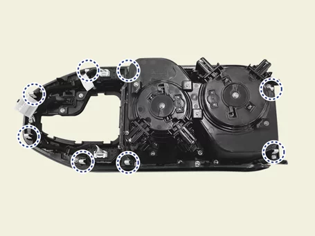
|
| 4.
|
Disconnect the console upper cover connector (A).
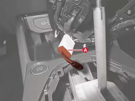
|
Manual Transaxle Type
| 1.
|
Disconnect the battery negative (-) terminal.
|
| 2.
|
Remove the hand brake cover (A).
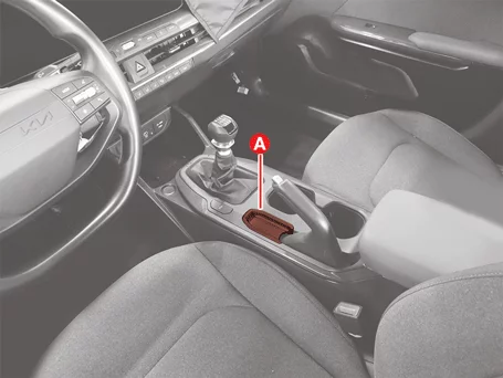
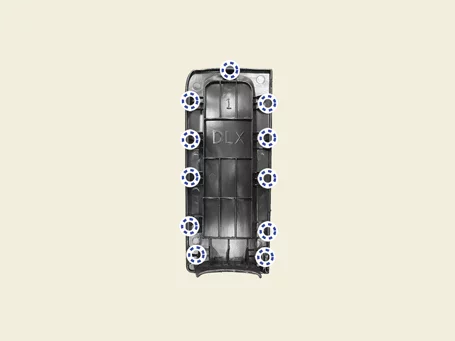
|
| 3.
|
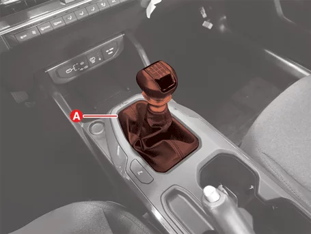
Remove the gear knob (A).
|
| 4.
|
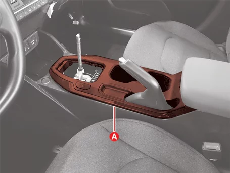
Remove the console upper cover (A).
|
| 5.
|
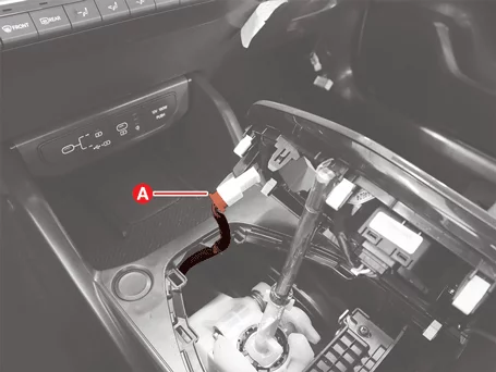
Disconnect the console upper cover connector (A).
|
| 1.
|
Install in the reverse order of removal.
|
Floor Console Upper Cover Disassembly and Reassembly
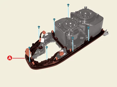
Upper Cover Garnish
| 1.
|
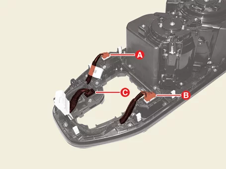
Disconnect the connectors (A, B, C).
A : Auto hold switch connector
B : Driver parking assistance switch connector
C : Shift lever indicator connector
|
| 2.
|
Remove the garnish (A) after removing the screws.
|
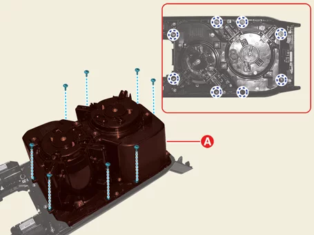
Cup Holder
| 1.
|
Remove the upper cover garnish.
|
| 2.
|
Remove the cup holder (A) after removing the screws.
|
| 1.
|
Reassemble in the reverse order of disassembly.
|
Other information:
Kia K4 (CL4) 2025-2026 Service Manual: Indicator lights
Electronic Stability Control (ESC) indicator light
The ESC system is a critical safety feature of your Kia K4. This indicator light operates as follows:
It illuminates for approximately 3 seconds as a system self-diagnostic check whenever you turn the ENGINE START/STOP button to the ON position.
If the light remains illuminated, it indicates a malfunction in the ESC system.
Kia K4 (CL4) 2025-2026 Service Manual: Wipers and washers
The windshield and rear window wiper and washer systems on the Kia K4 are designed to efficiently clear away rain, snow, road grime, and other foreign substances. Maintaining a clean windshield is critical for optimal visibility and safe driving in your Kia K4.