Contents:
Components and Components Location
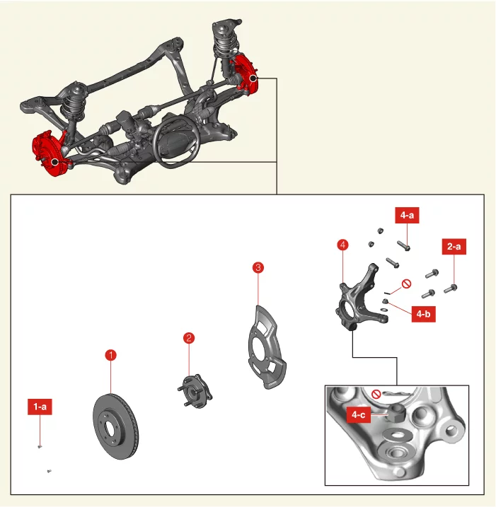
1. Front Brake Disc
1-a. 4.9 - 5.9 N·m (0.5
- 0.6
kgf·m, 3.6 - 4.3 lb·ft, 43.4 - 52.1 lb·in)
2. Front Hub Assembly
2-a. 78.5 - 98.1 N·m (8.0 -
10.0 kgf·m,
57.9 - 72.3 lb·ft)
3. Front Dust Cover
|
4. Front Knuckle
4-a. 156.9 - 176.5 N·m
(16.0 -
18.0 kgf·m, 115.7 - 130.2 lb·ft)
4-b. 34.3 - 44.1 N·m (3.5 - 4.5 kgf·m, 25.3 - 32.5
lb·ft)
4-c. 68.6 -
80.4 N·m (7.0 - 8.2 kgf·m, 50.6 - 59.3 lb·ft)
|
Front Dust Cover Removal and Installation
| 1.
|
Remove the front hub assembly.
(Refer to Front Axle Assembly - "Front Hub Assembly")
|
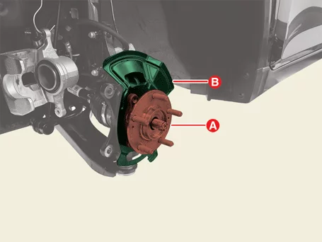
Front dust cover (B) and the hub assembly (A) are separated without any bolt or
nut, be careful
not to drop them while removing or installing.
|
|
| 1.
|
Install in the reverse order of removal.
|
Install to the specified torque.
|
|
Front Dust Cover Inspection
| 1.
|
Check the dust cover for cracks.
|
Front Hub Assembly Removal and Installation
Tool Name / Number
|
Illustration
|
Description
|
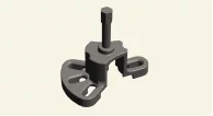
CV joint puller
09517 - 4E000
|
|
Used for removal of CV joint
|
| 1.
|
Remove the front brake disc.
(Refer to Brake System - "Front Brake Disc")
|
| 2.
|
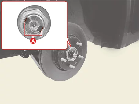
Unlock the driveshaft lock nut caulking (A), by hammering on a chisel or suitable tool.
|
| 3.
|
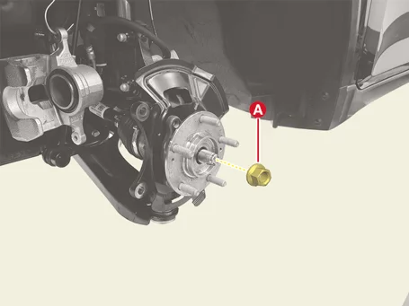
Remove the driveshaft lock nut (A).
|
Tightening torque :
274.6 - 294.2 N·m (28.0 - 30.0 kgf·m, 202.5 - 217.0 lb·ft)
|
|
| 4.
|
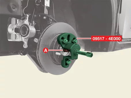
Separate the front driveshaft (A) from the front axle by using SST (09517 - 4E000).
|
| 5.
|
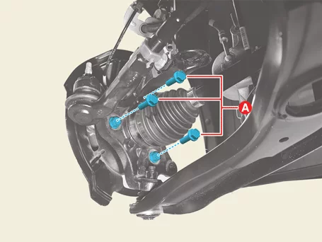
Remove the front hub assembly bolts (A).
|
Tightening torque :
78.5 - 98.1 N·m (8.0 - 10.0 kgf·m, 57.9 - 72.3 lb·ft)
|
|
| 6.
|
Remove the front hub assembly (A) and front dust cover (B).
|
| 1.
|
Install in the reverse order of removal.
|
•
|
Install to the specified torque.
|
|
•
|
Do not reuse the driveshaft lock nut.
|
|
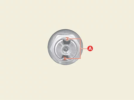
•
|
After tightening the driveshaft lock nut, caulk the lock nut to
an appropriate depth (A)
by using a chisel or suitable tool at more than 2 points.
|
Caulking Depth
(A) :
1.5 mm (0.059 in.) or more
|
|
|
•
|
Press the brake pedal to prevent the driveshaft from rotating
when tightening the
driveshaft lock nut.
|
|
|
Front Hub Assembly Inspection
| 1.
|
Check the hub bearing for cracks and wear on the drive shaft splines.
|
| 2.
|
Check the hub bearing assembly for defects and noise.
|
Front Knuckle Removal and Installation
Tool Name / Number
|
Illustration
|
Description
|
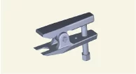
Ball joint puller
09568 - 1S100
|
|
Used for removal of tie rod end and lower arm ball joint
|
CV joint puller
09517 - 4E000
|
|
Used for removal of CV joint
|
| 1.
|
Remove the front wheel and tires.
(Refer to Suspension System - "Wheel")
|
| 2.
|
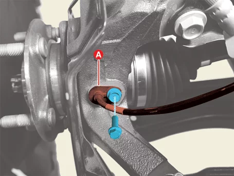
Remove the front wheel speed sensor (A) after removing the bolt.
|
Tightening torque :
8.8 - 13.7 N·m (0.9 - 1.4 kgf·m, 6.5 - 10.1 lb·ft)
|
|
| 3.
|
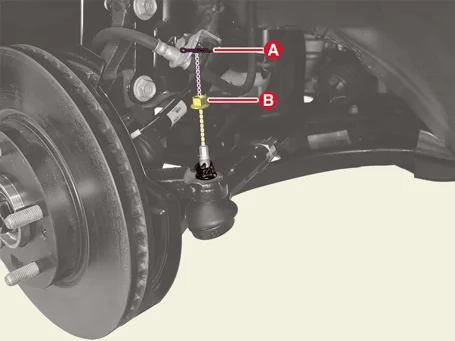
Separate the tie rod end ball joint from the front knuckle.
| (1)
|
Remove the split pin (A).
|
| (2)
|
Remove the lock nut (B).
|
Tightening torque :
34.3 - 44.1 N·m (3.5 - 4.5 kgf·m, 25.3 - 32.5 lb·ft)
|
|
•
|
Do not reuse the split pin.
|
|
•
|
Do not reuse the lock nut.
|
|
•
|
Be careful not to damage the ball joint boot.
|
|
•
|
Use a hand tool when removing or installing the
lock nut.
|
|
|
| (3)
|
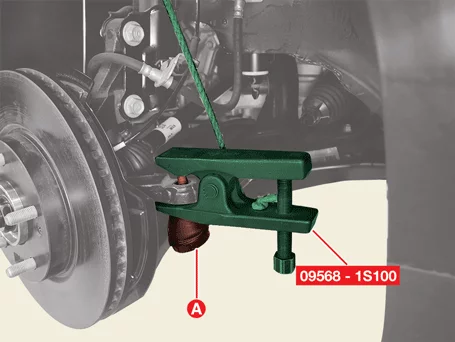
Separate the tie rod end ball joint (A) using SST (09568 - 1S100).
|
|
| 4.
|
Separate the lower arm ball joint from the front knuckle.
| (1)
|
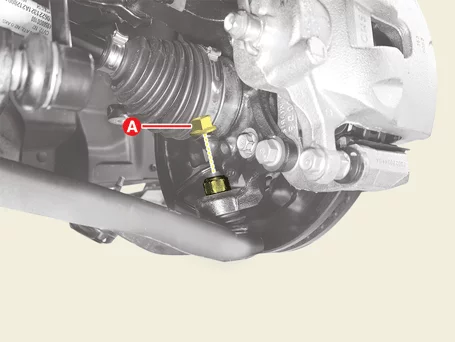
Remove the lock nut (A).
|
Tightening torque :
68.6 - 80.4 N·m (7.0 - 8.2 kgf·m, 50.6 - 59.3 lb·ft)
|
|
•
|
Do not reuse the lock nut.
|
|
•
|
Be careful not to damage the ball joint boot.
|
|
•
|
Use a hand tool when removing or installing the
lock nut.
|
|
|
| (2)
|
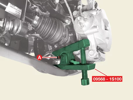
Separate the lower arm ball joint (A) using SST (09568 - 1S100).
|
|
| 5.
|
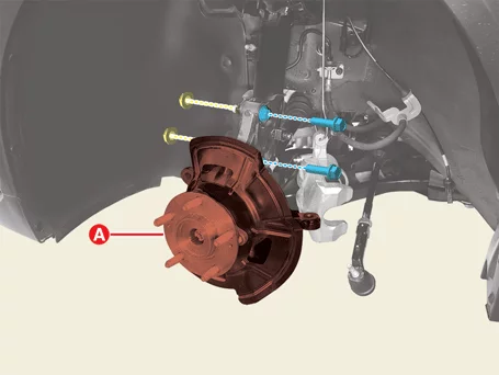
Remove the front knuckle (A) after removing the bolts and nuts.
|
Tightening torque :
156.9 - 176.5 N·m (16.0 - 18.0 kgf·m, 115.7 - 130.2 lb·ft)
|
|
| 6.
|
Remove the front hub assembly after removing the bolts (A).
|
Tightening torque :
78.5 - 98.1 N·m (8.0 - 10.0 kgf·m, 57.9 - 72.3 lb·ft)
|
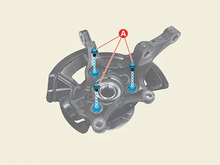
|
| 1.
|
Install in the reverse order of removal.
|
Install to the specified torque.
|
|
| 2.
|
Check the alignment.
(Refer to Suspension System - "Alignment")
|
Front Knuckle Inspection
| 1.
|
Check the front knuckle for cracks.
|
Other information:
Kia K4 (CL4) 2025-2026 Service Manual: Smart Cruise Control display and control
You can conveniently monitor the current status and operational state of the Smart Cruise Control (SCC) system by navigating to the "Driving Assist" view on your Kia K4 instrument cluster. For further details on customizing these views, please refer to your owner's manual section on LCD display modes.
The Kia K4 instrument cluster provides clear visual feedback regarding the SCC status through various indicators:
When the system is active and operating:
Shows whether a lead vehicle is detected ahead and highlights the current vehicle-to-vehicle distance level setting.
Kia K4 (CL4) 2025-2026 Service Manual: Forward Collision-Avoidance Assist (FCA) (Sensor Fusion)
Basic function
The Forward Collision-Avoidance Assist (FCA) system in your Kia K4 is designed to proactively monitor the road ahead. By utilizing advanced sensor fusion technology, it can detect vehicles, motorcyclists, pedestrians, or cyclists in your path.