Contents:
Components and Components Location
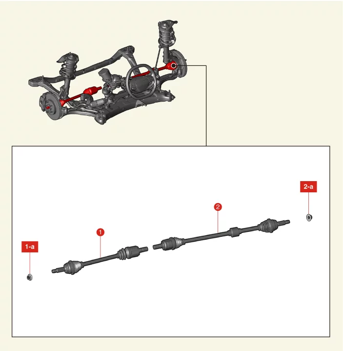
1. Front Driveshaft (LH)
1-a. 274.6 - 294.2
N·m
(28.0 - 30.0 kgf·m, 202.5 - 217.0 lb·ft)
|
2. Front Driveshaft (RH)
2-a. 274.6 - 294.2
N·m
(28.0 - 30.0 kgf·m, 202.5 - 217.0 lb·ft)
|
Front Driveshaft Removal and Installation
Tool Name / Number
|
Illustration
|
Description
|
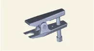
Ball joint puller
09568 - 1S100
|
|
Used for removal of tie rod end and lower arm ball joint
|
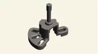
CV joint puller
09517 - 4E000
|
|
Used for removal of CV joint
|
| 1.
|
Remove the front wheel and tires.
(Refer to Suspension System - "Wheel")
|
| 2.
|
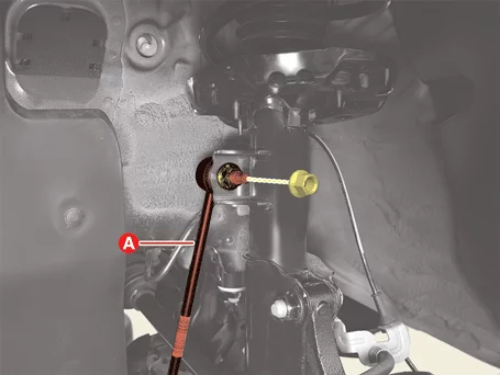
Remove the stabilizer bar link (A) from the front strut assembly after removing the nut.
|
Tightening torque :
98.1 - 117.7 N·m (10.0 - 12.0 kgf·m, 72.3 - 86.8 lb·ft)
|
|
•
|
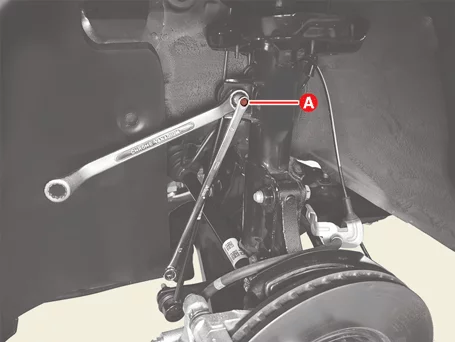
When removing and installing the stabilizer bar link nut, fix
the outer hexa stud (A) of
the link.
|
|
•
|
Be careful not to damage the boot of the link.
|
|
•
|
Use only a hand tool when removing or installing the stabilizer
bar link nut.
|
|
|
| 3.
|
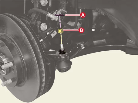
Separate the tie rod end ball joint from the front knuckle.
| (1)
|
Remove the split pin (A).
|
| (2)
|
Remove the lock nut (B).
|
Tightening torque :
34.3 - 44.1 N·m (3.5 - 4.5 kgf·m, 25.3 - 32.5 lb·ft)
|
|
•
|
Do not reuse the split pin.
|
|
•
|
Do not reuse the lock nut.
|
|
•
|
Be careful not to damage the ball joint boot.
|
|
•
|
Use a hand tool when removing or installing the
lock nut.
|
|
|
| (3)
|
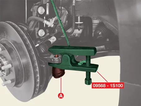
Separate the tie rod end ball joint (A) using SST (09568 - 1S100).
|
|
| 4.
|
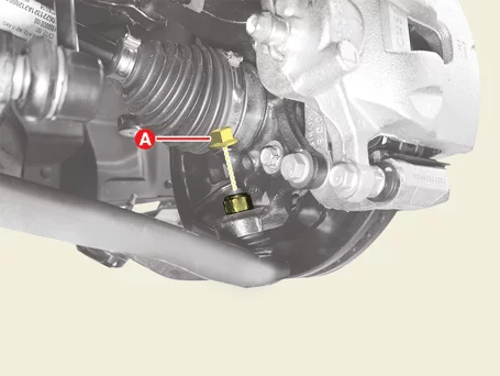
Separate the lower arm ball joint from the front knuckle.
| (1)
|
Remove the lock nut (A).
|
Tightening torque :
68.6 - 80.4 N·m (7.0 - 8.2 kgf·m, 50.6 - 59.3 lb·ft)
|
|
•
|
Do not reuse the lock nut.
|
|
•
|
Be careful not to damage the ball joint boot.
|
|
•
|
Use a hand tool when removing or installing the
lock nut.
|
|
|
| (2)
|
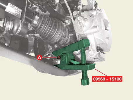
Separate the lower arm ball joint (A) using SST (09568 - 1S100).
|
|
| 5.
|
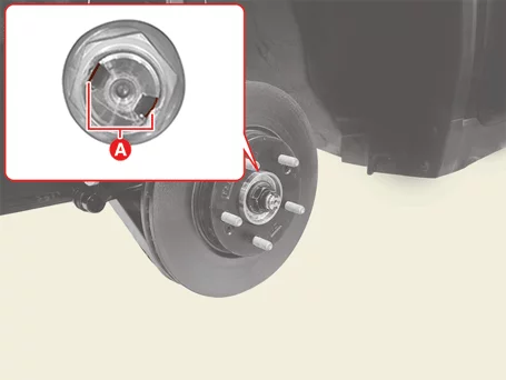
Unlock the driveshaft lock nut caulking (A) by hammering on a chisel or suitable tool.
|
| 6.
|
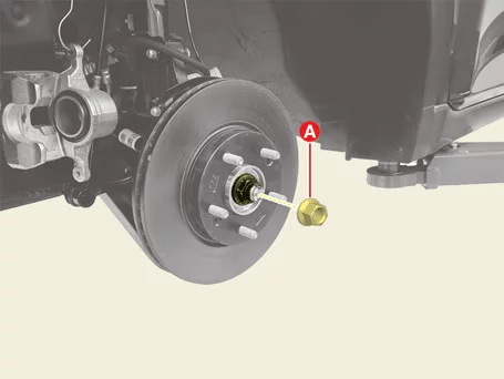
Remove the driveshaft lock nut (A).
|
Tightening torque :
274.6 - 294.2 N·m (28.0 - 30.0 kgf·m, 202.5 - 217.0 lb·ft)
|
|
| 7.
|
Separate the front driveshaft (A) from the front axle by using SST (09517 - 4E000).
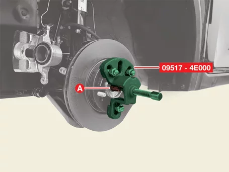
|
| 8.
|
Separate the front driveshaft (A) with the front axle assembly (B).
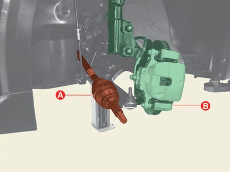
|
Do not force pull or deflect the axle excessively when removing the driveshaft.
|
|
| 9.
|
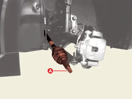
Remove the front driveshaft (A) using a suitable tool.
[LH]
[RH]
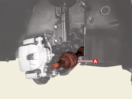
|
•
|
Do not insert the tool such as the pry bar too deep, as this
may damage the oil seal.
|
|
•
|
Do not pull the driveshaft with excessive force. it may occur
the inside of the joint kit
is dislocated, and may damage the boot or bearing.
|
|
•
|
Plug the hole of the transaxle case with the oil seal cap to
prevent contamination.
|
|
•
|
Support the driveshaft properly when removing it to prevent it
from falling.
|
|
|
| 1.
|
Install in the reverse order of removal.
|
•
|
Install to the specified torque.
|
|
•
|
Do not reuse the driveshaft lock nut.
|
|
•
|
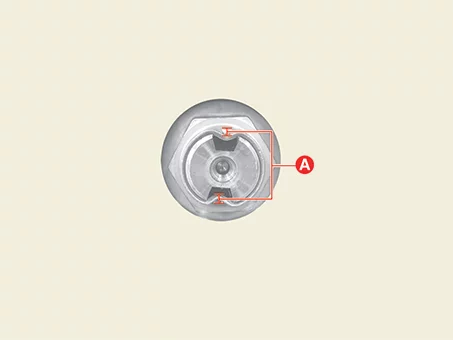
After tightening the driveshaft lock nut, caulk the lock nut to
an appropriate depth (A)
by using a chisel or suitable tool at more than 2 points.
|
Caulking Depth
(A) :
1.5 mm (0.059 in.) or more
|
|
|
•
|
Press the brake pedal to prevent the driveshaft from rotating
when tightening the
driveshaft lock nut.
|
|
|
Joint Assembly (Transaxle side) Components and Components Location
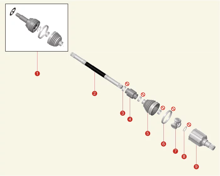
1. Joint Assembly (Wheel Side)
2.
Driveshaft
3.
Dynamic Damper Boot Band
4. Dynamic Damper
5. Joint Boot (Transaxle Side)
|
6. Joint Boot Band (Transaxle Side)
7.
Spider
Assembly
8. Snap Ring
9. Joint Housing (Transaxle Side)
|
|
Do not remove the wheel side joint housing from the shaft.
|
Joint Assembly (Transaxle side) Removal
Tool Name / Number
|
Illustration
|
Description
|
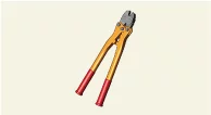
Band installer
0K495 - 2W001
|
|
Used for installing hook type boot band (low profile)
|
|
•
|
Driveshaft joints require special grease, so do not add any other type of
grease.
|
|
•
|
When replacing the boot band, it must be a new one.
|
|
| 1.
|
Remove the front driveshaft.
(Refer to Driveshaft and Axle - "Front Driveshaft")
|
| 2.
|
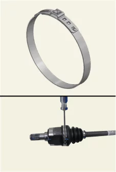
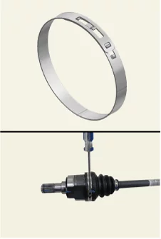
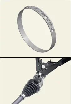
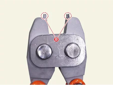
Remove the transaxle side large diameter (A) and small diameter (B) boot bands.
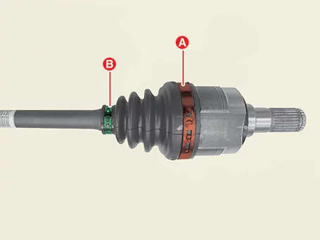
Use the right tool for each type of boot band as shown in the table below.
Ear Type
|
Hook Type
|
Hook Type
[Low
profile]
|
Flat-head screwdriver
|
Flat-head screwdriver
|
SST (0K495 - 2W001)
|
|
|
|
|
|
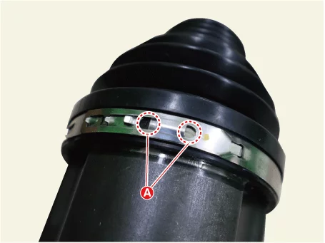
When using the low profile hook type boot band, fit the SST tip
(B) into the boot band
hole (A) as shown below.
|
|
|
| 3.
|
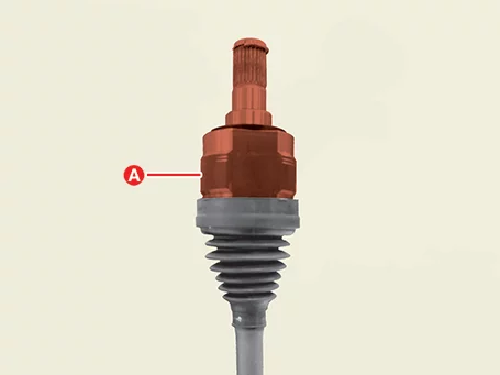
Remove the transaxle joint housing (A).
|
| 4.
|
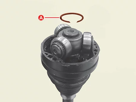
Remove the snap ring (A) using a snap ring pliers.
|
| 5.
|
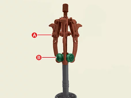
Remove the spider assembly (B) from the driveshaft using a puller (A).
|
| 6.
|
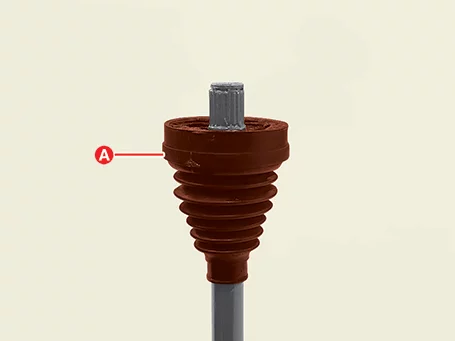
Remove transaxle side boot (A).
|
| 7.
|
Clean the inside of the spider assembly and joint housing.
|
Remove grease inside the housing as much as possible.
|
|
Joint Assembly (Transaxle side) Inspection
| 1.
|
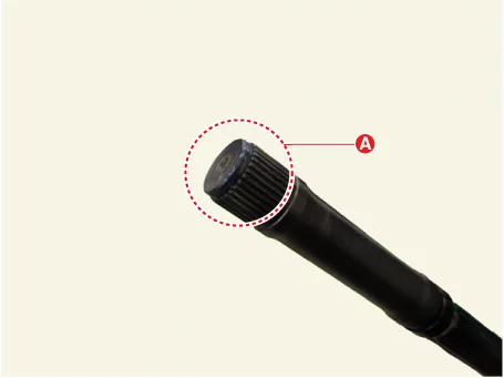
Check spline (A) for damage / wear / crack.
|
| 2.
|
Check the boot for water or foreign objects.
|
| 3.
|
Check joint assembly for damage / wear / crack and rust.
|
| 4.
|
Replace any defective parts.
|
Joint Assembly (Transaxle side) Installation
Tool Name / Number
|
Illustration
|
Description
|
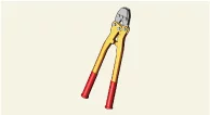
Band installer
0K495 - C5000
|
|
Used for installing of ear type boot band
(Sharing handle with 0K495 - 2W001)
|
Band installer
0K495 - 2W001
|
|
Used for installing hook type boot band (low profile)
|
Band installer
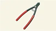
09495 - 39100
|
|
Used for installing hook type boot band
|
|
•
|
Be careful of dust or foreign substances entering when assembling.
|
|
•
|
Driveshaft joints require special grease, so do not add any other type of
grease.
|
|
•
|
When replacing the boot band, it must be a new one.
|
|
| 1.
|
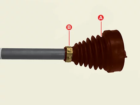
Install the transaxle side boot (A) and boot band (B) on the driveshaft.
|
Put the boot band (B) first on the driveshaft before installing the boot (A).
|
|
| 2.
|
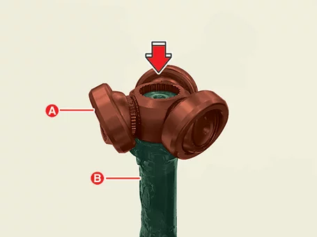
Install the spider assembly (A) on the shaft (B), then press it using a rubber mallet.
|
•
|
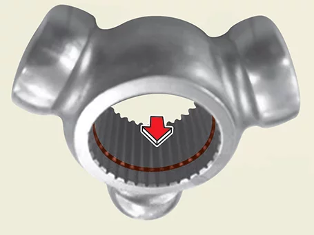
When installing the spider assembly (A), install it in the
correct direction.
|
|
•
|
Installing in the wrong direction can cause secondary quality
problems.
|
|
|
| 3.
|
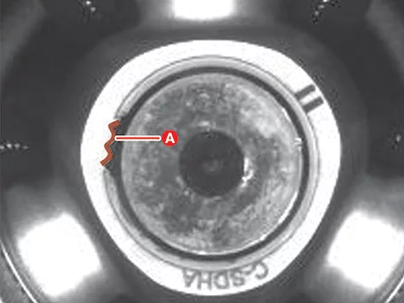
Install the snap ring (A) using the snap ring pliers.
|
•
|
When replacing the joint assembly, use the new one provided in
the joint kit.
|
|
•
|
Do not reuse the snap ring.
|
|
•
|
After installing the snap ring, make sure that there are only 2
- 3 splines in position
(A).
|
|
|
| 4.
|
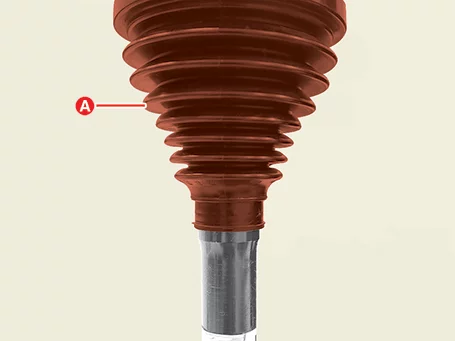
Install the transaxle side joint boot (A) in the correct position.
|
•
|
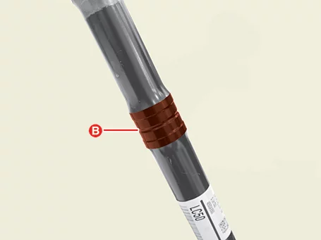
When installing boot (A), make sure the boot fits into the
groove (B).
|
|
•
|
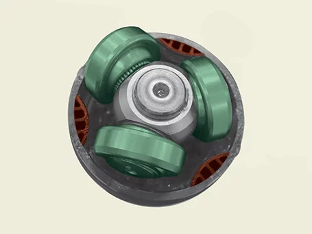
When installing the spider assembly, fit the assembly to the
boot shape.
|
|
|
| 5.
|
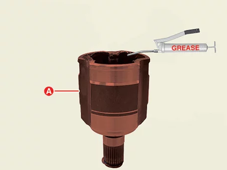
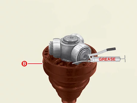
Apply specified grease inside the joint housing (A) and boot (B).
|
•
|
Use the grease provided with the joint/boot kit.
|
|
•
|
Apply about 70% grease to the housing (A) and about 30% grease
to the boot (B).
|
|
•
|
Driveshaft joints require special grease, so do not add any
other type of grease.
|
|
|
| 6.
|
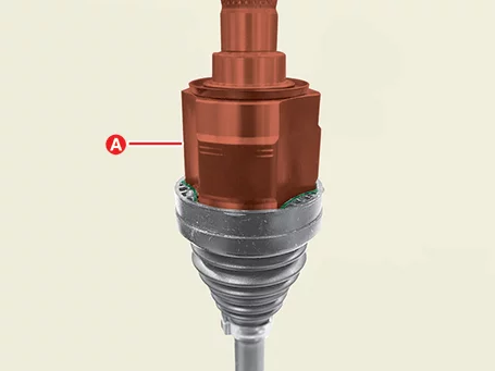
Install the transaxle side joint housing (A).
|
•
|
When installing the housing, turn the boot to fit each other.
|
|
•
|
If the shape of housing and boot does not fit, there is a
possibility of leakage due to
the gap. Be very careful.
|
|
|
| 7.
|
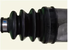
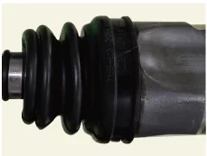
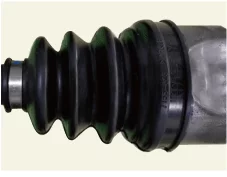
Adjust the air inside the boot to normal as shown below.
Normal
|
Lack of air
|
Too much air
|
|
|
|
|
|
| 8.
|
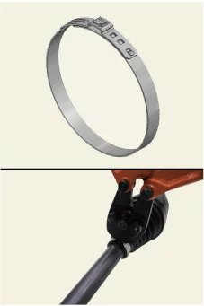
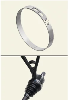
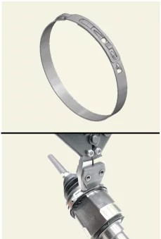
Install the transaxle side joint large diameter (A) and small diameter (B) boot band.
Refer to the below and select the correct tool for each boot band type.
Ear Type
|
Hook Type
|
Hook Type
[Low
profile]
|
SST (0K495 - C5000)
|
SST (09495 - 39100)
|
SST (0K495 - 2W001)
|
|
|
|
|
|
•
|
Install in the following order : large diameter
boot band (A) → small diameter
boot band (B).
|
|
•
|
Installing in the wrong order can cause leaks.
|
|
•
|
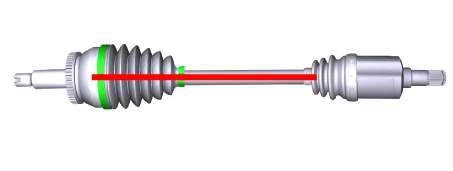
When installing the boot band, align the
fastened direction with the wheel side
joint boot band.
|
|
•
|
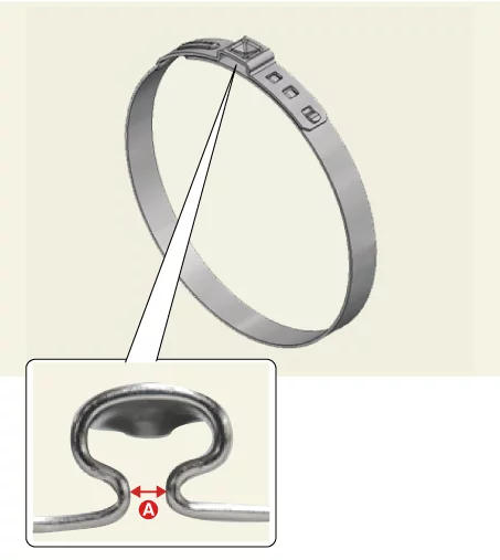
When installing the ear type boot band, check
the clearance (A) as shown below.
|
Ear
type clearance (A) : 2.0 mm
(0.787
in.) or less
|
|
|
•
|
When using the low profile hook type boot band,
fit the SST tip (B) into the boot
band hole (A) as shown below.
|
|
|
|
| 9.
|
Install the front driveshaft.
(Refer to Driveshaft and Axle - "Front Driveshaft")
|
Dynamic Damper Components and Components Location
1. Joint Assembly (Wheel Side)
2.
Driveshaft
3.
Dynamic Damper Boot Band
4. Dynamic Damper
5. Joint Boot (Transaxle Side)
|
6. Joint Boot Band (Transaxle Side)
7.
Spider
Assembly
8. Snap Ring
9. Joint Housing (Transaxle Side)
|
|
Do not remove the wheel side joint housing from the shaft.
|
Dynamic Damper Removal
| 1.
|
Remove the front driveshaft.
(Refer to Driveshaft Assembly - "Front Driveshaft")
|
| 2.
|
Remove the transaxle side joint.
(Refer to Driveshaft Assembly - "Joint Assembly (Transaxle
Side)")
|
| 3.
|
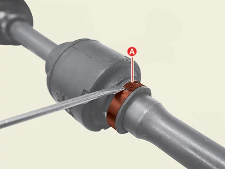
Remove the dynamic damper band (A) using a flat head screwdriver.
|
When removing the dynamic damper, lubricate the shaft with soapy water to
prevent shaft damage.
|
|
| 4.
|
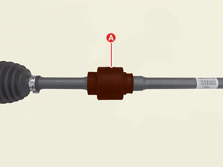
Remove the dynamic damper (A).
|
Dynamic Damper Installation
Tool Name / Number
|
Illustration
|
Description
|
Band installer
09495 - 39100
|
|
Used for installing hook type boot band
|
| 1.
|
Install the dynamic damper (A).
|
| 2.
|
Tighten the dynamic damper band (A) using the SST (09495 - 39100).
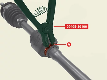
|
When installing the dynamic damper (A), make sure that the damper fits into the
groove (B).
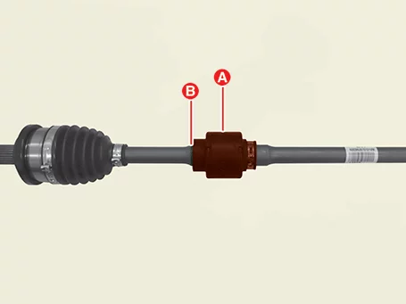
|
|
| 3.
|
Install the transaxle side joint.
(Refer to Driveshaft Assembly - "Joint Assembly (Transaxle
Side)")
|
| 4.
|
Install the front driveshaft.
(Refer to Driveshaft Assembly - "Front Driveshaft")
|
Joint Assembly (Wheel side) Components and Components Location
1. Joint Assembly (Wheel Side)
2.
Driveshaft
3.
Dynamic Damper Boot Band
4. Dynamic Damper
5. Joint Boot (Transaxle Side)
|
6. Joint Boot Band (Transaxle Side)
7.
Spider
Assembly
8. Snap Ring
9. Joint Housing (Transaxle Side)
|
|
Do not remove the wheel side joint housing from the shaft.
|
Joint Assembly (Wheel side) Removal
When able to replace the wheel side joint boot
| 1.
|
Remove the front driveshaft.
(Refer to Driveshaft Assembly - "Front Driveshaft")
|
| 2.
|
Remove the joint assembly (transaxle side).
(Refer to Driveshaft Assembly - "Joint Assembly (Transaxle
Side)")
|
| 3.
|
Remove the wheel side joint small diameter (A) and large diameter (B) boot band using a
flat-head screw
driver.
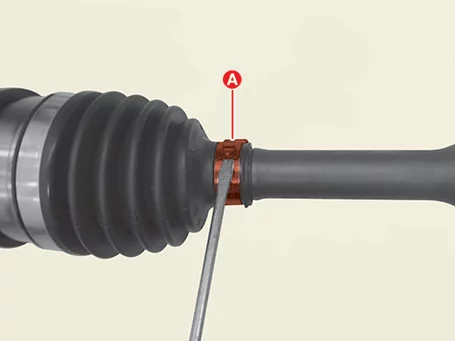
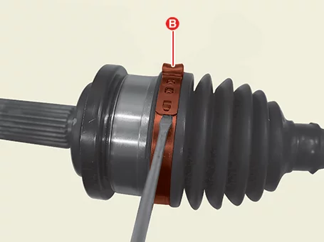
|
| 4.
|
Remove the wheel side joint boot (A).
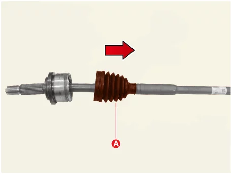
|
•
|
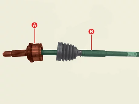
Do not remove the wheel side joint housing (A).
|
|
•
|
The wheel side joint boot can not be replaced, so replace the
wheel side joint assembly
(A) and shaft (B) together as an assembly.
|
|
|
When unable to replace the wheel side joint boot
| 1.
|
Remove the front driveshaft.
(Refer to Driveshaft Assembly - "Front Driveshaft")
|
| 2.
|
Remove the joint assembly (transaxle side).
(Refer to Driveshaft Assembly - "Joint Assembly (Transaxle
Side)")
|
| 3.
|
Replace the wheel side joint assembly (A) and shaft (B).
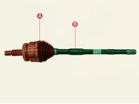
|
|
The wheel side joint boot can not be replaced, so replace the wheel side joint assembly (A) and
shaft (B)
together as an assembly.
|
Joint Assembly (Wheel side) Inspection
| 1.
|
Check the boot for water or foreign objects.
|
| 2.
|
Replace any defective parts.
|
Joint Assembly (Wheel side) Installation
Tool Name / Number
|
Illustration
|
Description
|
Band installer
0K495 - C5000
|
|
Used for installing of ear type boot band
(Sharing handle with 0K495 - 2W001)
|
When able to replace the wheel side joint boot
|
•
|
Be careful of dust or foreign substances entering when assembling.
|
|
•
|
Driveshaft joints require special grease, so do not add any other type of
grease.
|
|
•
|
When replacing the boot band, it must be a new one.
|
|
| 1.
|
Install the new boot (A) in the direction of the arrow.
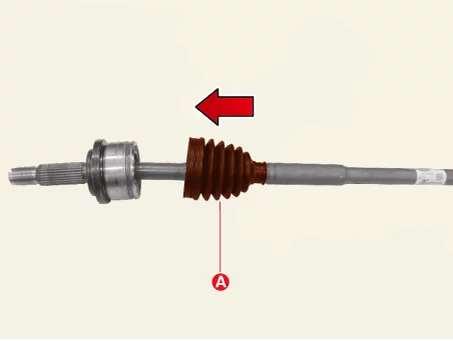
|
| 2.
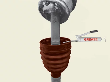
|
Apply the specified grease inside the boot.
|
•
|
Use the grease provided with the joint/boot kit.
|
|
•
|
Apply about 50 - 60% grease inside the boot.
|
|
•
|
Driveshaft joints require special grease, so do not add any
other type of grease.
|
|
|
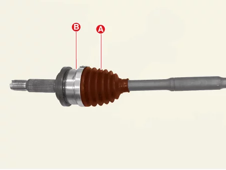
| 3.
|
Install the wheel side boot (A) into the housing (B).
|
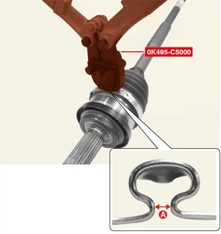
| 4.
|
Install the large diameter boot band using SST (0K495 - C5000).
|
Ear type clearance (A) :
2.0 mm (0.078 in.) or less
|
|
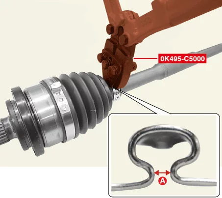
| 5.
|
Install the small diameter boot band using SST (0K495 - C5000).
|
Ear type clearance (A) :
2.0 mm (0.078 in.) or less
|
|
When installing the boot band, align the fastened direction with the wheel side
joint large
diameter boot band.
|
|
| 6.
|
Install the transaxle side joint.
(Refer to Driveshaft Assembly - "Joint Assembly (Transaxle
Side)")
|
| 7.
|
Install the front driveshaft.
(Refer to Driveshaft Assembly - "Front Driveshaft")
|
When unable to replace the wheel side joint boot
|
•
|
Be careful of dust or foreign substances entering when assembling.
|
|
•
|
Driveshaft joints require special grease, so do not add any other type of
grease.
|
|
•
|
When replacing the boot band, it must be a new one.
|
|
| 1.
|
Replace the wheel side assembly (A) and shaft (B).
|
The wheel side joint boot can not be replaced, so replace the wheel side joint
assembly (A) and
shaft (B) together as an assembly.
|
|
| 2.
|
Install the transaxle side joint.
(Refer to Driveshaft Assembly - "Joint Assembly (Transaxle
Side)")
|
| 3.
|
Install the front driveshaft.
(Refer to Driveshaft Assembly - "Front Driveshaft")
|
Other information:
Kia K4 (CL4) 2025-2026 Service Manual: Driver assistance guide
WARNING
Driver responsibility
As the driver of the Kia K4, you must never rely solely on the Driver Assistance Systems. These sophisticated technologies are designed to support you, but they are not a substitute for active driver engagement, constant vigilance, and safe driving practices. These systems operate on the premise that the operator maintains full control of the vehicle, and they are intended to mitigate collision impact or provide assistance under normal driving conditions.
Kia K4 (CL4) 2025-2026 Service Manual: Inside rearview mirror
Adjust the inside rearview mirror so that you can view the entire rear window clearly from your driving position. Ensure this adjustment is finalized before you begin your journey in the Kia K4.
To maintain a clear view, avoid placing bulky items, boxes, or passengers in the rear seat or cargo area that could obstruct the rear window visibility.
WARNING
Mirror adjustment
For your safety, never attempt to adjust the rearview mirror while the Kia K4 is in motion.