Contents:
Components and Components Location
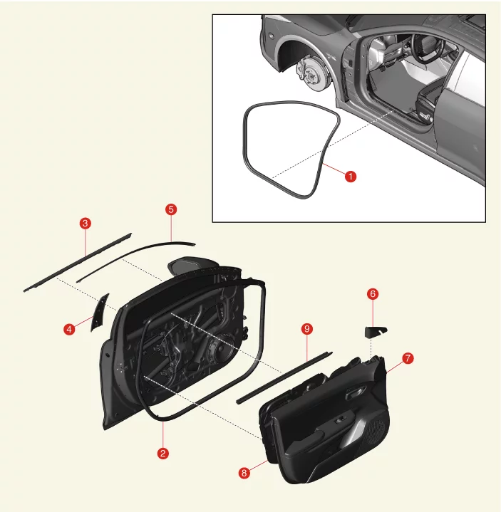
1. Body Side Weather Strip
2. Door Side
Weather
Strip
3. Outside Door Belt Weather Strip
4. Door Garnish
5. Door Molding
|
6. Delta Inner Cover
7. Door Trim
8.
Door Trim
Seal
9. Inside Door Belt Weather Strip
|
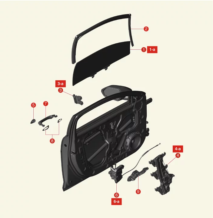
1. Door Glass
2. Door Glass Run
3. Door
Channel
4. Power Window Regulator
|
5. Door Handle Cover
6. Door Latch
7.
Door
Handle
8. Door Handle Gaskets
|
Adjustment
Glass Adjustment
|
Check the glass run and channel for damage and replace if necessary.
|
| 1.
|
Remove the front door trim seal.
(Refer to Front Door - "Front Door Trim")
|
| 2.
|
Operate the power window switch to lower the window glass until the window glass bolt is
visible in the
service hole.
|
| 3.
|
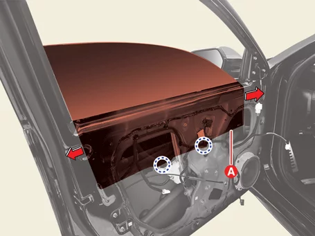
Adjust the gap after moving the front door window glass (A) up, down, left and right, and then
tighten
the bolts.
|
Tightening torque :
7.8 - 11.8 N·m (0.8 - 1.2 kgf·m, 5.8 - 8.7 lb·ft)
|
|
| 4.
|
Check that the glass operates properly.
|
Striker Adjustment
| 1.
|
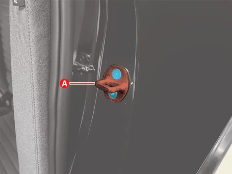
Loosen the bolts and adjust the striker (A) by moving it back and forth, left and right, and
then tighten
the bolts.
|
Tightening torque :
18.2 - 33.7 N·m (1.86 - 3.44 kgf·m, 13.5 - 24.9 lb·ft)
|
|
| 2.
|
Check that the door opens and closes properly.
|
Door Adjustment
| 1.
|
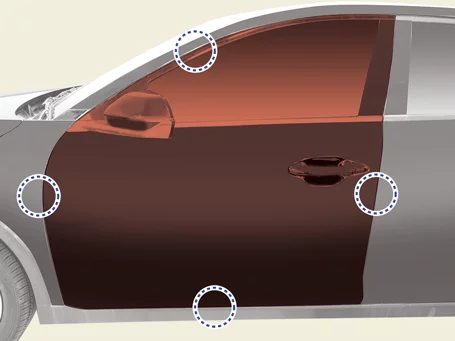
Check that the gap between the door and the body is even after parking in a flat level.
|
| 2.
|
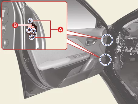
Loosen the door hinge bolts (A, B), adjust the door by moving it back and forth, left and
right, and then
tighten the bolts.
|
Tightening torque
A : 21.6 - 26.5 N·m (2.2 - 2.7 kgf·m,
15.9 - 19.5 lb·ft)
B : 23.5 - 31.4 N·m (2.4 - 3.2 kgf·m,
17.4 - 23.1 lb·ft)
|
|
| 3.
|
Check that the gap between the door and the body is even.
|
Front Door Window Glass Removal and Installation
Door Window Glass
| 1.
|
Remove the front door trim seal.
(Remove the Front Door - "Front Door Trim")
|
| 2.
|
Remove the outside & inside door belt weather strip.
(Refer to Front Door - "Front Door Weather Strip")
|
| 3.
|
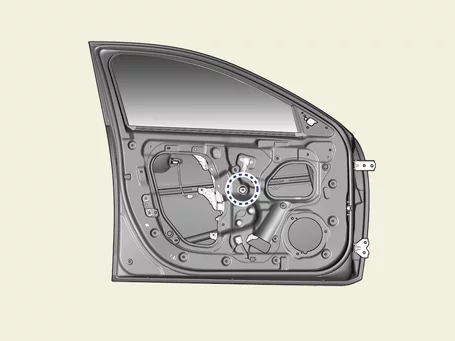
Operate the power window switch to lower the window glass until the window glass bolt is
visible in the
service hole.
|
| 4.
|
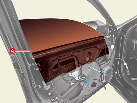
Remove the glass (A) after removing the bolts.
|
Tightening torque:
7.8 - 11.8 N·m (0.8 - 1.2 Kgf·m, 5.8 - 8.7 lb·ft)
|
|
Be careful not to damage the surface of glass.
|
|
Door Glass Run
| 1.
|
Remove the door window glass.
|
| 2.
|
Remove the glass run (A).
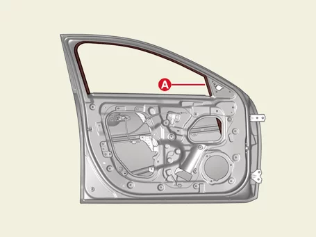
|
Door channel
| 1.
|
Remove the door window glass.
|
| 2.
|
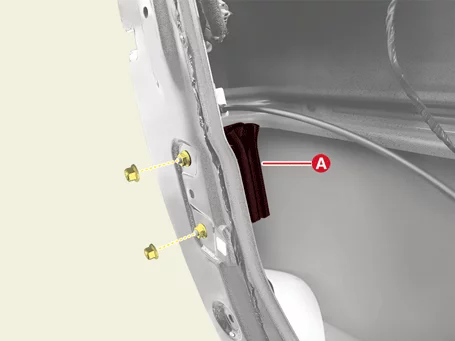
Remove the channel (A) after removing the nuts.
|
Tightening torque:
3.9 - 5.9 N·m (0.4 - 0.6 kgf·m, 2.9 - 4.3 lb·ft, 34.7 - 52.1 lb·in)
|
|
| 1.
|
Install in the reverse order of removal.
|
Front Door Garnish and Molding Removal and Installation
|
The indication below represents the location of a clip or fastener.

|
Door Garnish
| 1.
|
Remove the inside door belt weather strip.
(Refer to Front Door - "Front Door Weather Strip")
|
| 2.
|
Remove the garnish (A).
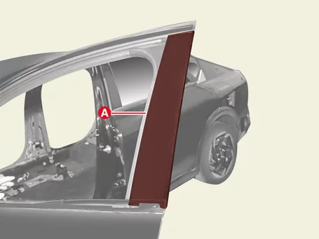
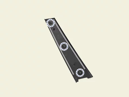
|
Door Molding
| 1.
|
Remove the door garnish.
|
| 2.
|
Remove the outside mirror assembly.
(Refer to Mirror - "Outside Mirror Assembly")
|
| 3.
|
Remove the molding (A).
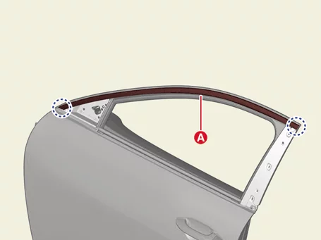
|
| 1.
|
Install in the reverse order of removal.
|
Front Door Handle Removal and Installation
Door Outside Handle
| 1.
|
Remove the front door window glass.
(Refer to Front Door - "Front Door Window Glass")
|
| 2.
|
Disconnect the handle connector (A).
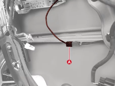
|
| 3.
|
Separate the latch rod (A).
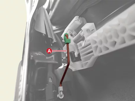
|
| 4.
|
Remove the handle cover (A) after loosening the bolt.
|
Tightening torque:
6.5 - 8.8 N·m (0.66 - 0.90 kgf·m, 4.8 - 6.5 lb·ft, 57.3 - 78.1 lb·in)
|
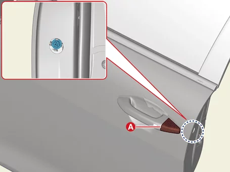
|
| 5.
|
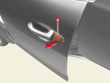
Remove the door lock (A) by pulling it in the direction of the arrow.
|
| 6.
|
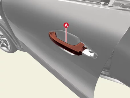
Remove the handle (A).
|
Front Door Outside Handle Base
| 1.
|
Remove the rear door outside handle.
|
| 2.
|
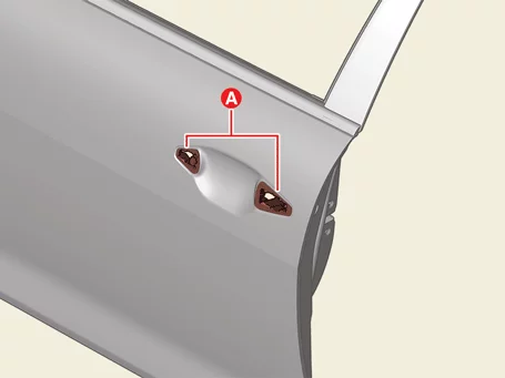
Remove the handle gaskets (A).
|
| 3.
|
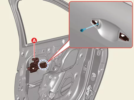
Remove the handle base (A) after removing the screw.
|
Tightening torque:
3.4 - 5.7 N·m (0.35 - 0.58 kgf·m, 2.5 - 4.2 lb·ft, 30.4 - 50.3 lb·in)
|
|
| 1.
|
Install in the reverse order of removal.
|
Front Door Latch Removal and Installation
| 1.
|
Remove the front door window glass.
(Refer to Front Door - "Front Door Window Glass")
|
| 2.
|
Remove the handle cover (A) after loosening the bolt.
|
| 3.
|
Remove the door lock (A) by pulling it in the direction of the arrow.
|
| 4.
|
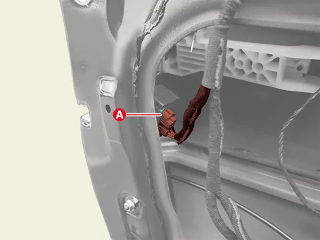
Disconnect the latch connector (A).
|
| 5.
|
Separate the latch rod (A).
|
| 6.
|
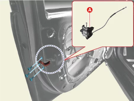
Remove the latch (A) after removing the bolts.
|
Tightening torque:
7.8 - 10.8 N·m (0.8 - 1.1 kgf·m, 5.8 - 8.0 lb·ft)
|
|
| 1.
|
Install in the reverse order of removal.
|
Front Door Latch Inspection
| 1.
|
Remove the front door trim seal.
(Refer to Front Door - "Front Door Trim")
|
| 2.
|
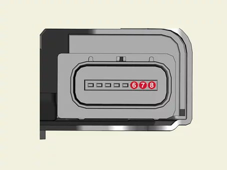
Apply voltage to connector terminal and check that the door latch operates properly.
Driver's Side
Passenger's Side
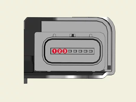
Pin number
|
Operate
|
Driver side
|
Passenger side
|
Lock
|
Unlock
|
8
|
2
|
+
|
-
|
7
|
1
|
-
|
+
|
|
Front Door Power Window Regulator Removal and Installation
| 1.
|
Remove the front door window glass.
(Refer to Front Door - "Front Door Window Glass")
|
| 2.
|
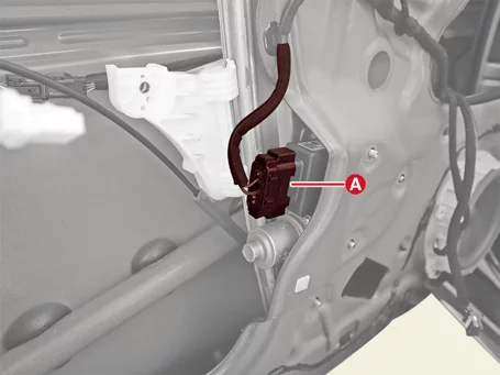
Disconnect the power window motor connector (A).
|
| 3.
|
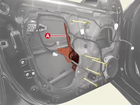
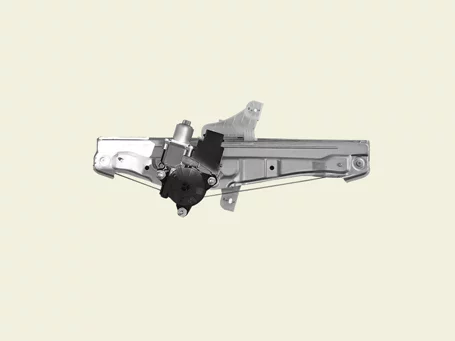
Remove the power window regulator (A) after removing the nuts.
|
Tightening torque:
3.9 - 5.9 N·m (0.4 - 0.6 kgf·m, 2.9 - 4.3 lb·ft, 34.7 - 52.1 lb·in)
|
|
| 1.
|
Install in the reverse order of removal.
|
Front Door Speaker Removal and Installation
|
The indication below represents the location of a clip or fastener.
|
| 1.
|
Remove the door trim.
(Refer to Front Door - "Front Door Trim")
|
| 2.
|
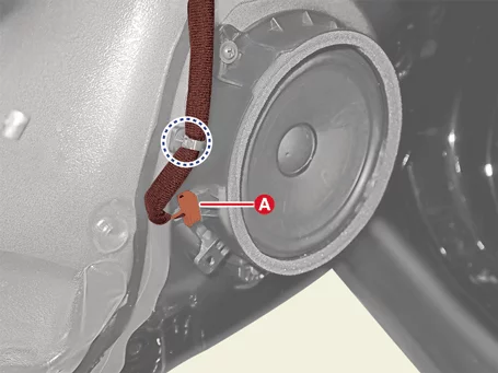
Disconnect the door speaker connector (A).
|
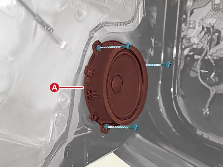
| 3.
|
Remove door speaker (A) after removing the screws.
|
| 1.
|
Install in the reverse order of removal.
|
Front Door Switch Removal and Installation
|
The indication below represents the location of a clip or fastener.
|
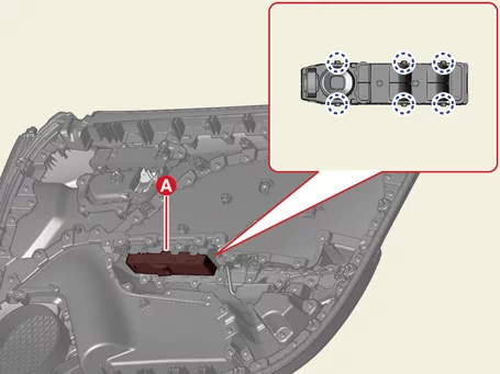
Power Window Main Switch
| 1.
|
Remove the front door trim. [Driver's side]
(Refer to Front Door - "Front Door Trim")
|
| 2.
|
Remove the switch (A).
|
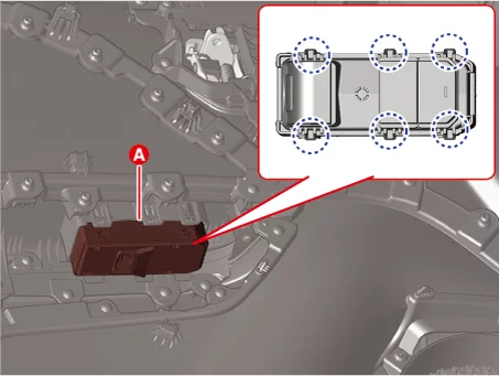
Power Window Sub Switch
| 1.
|
Remove the front door trim. [Passenger's side]
(Refer to Front Door - "Front Door Trim")
|
| 2.
|
Remove the switch (A).
|
| 1.
|
Install in the reverse order of removal.
|
Front Door Trim Removal and Installation
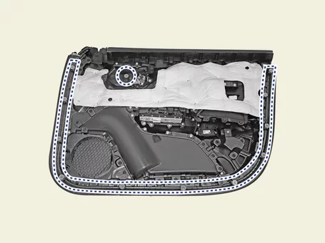
|
The indication below represents the location of a clip or fastener.
|
Door Trim
| 1.
|
Disconnect the battery negative (-) terminal.
|
| 2.
|
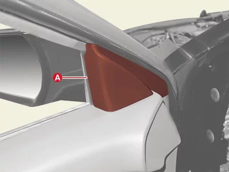
Remove the quadrant inner cover (A).
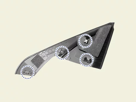
|
| 3.
|
Open the screw cap (A).
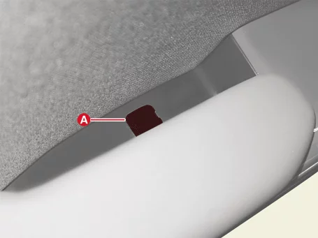
|
| 4.
|
Remove the trim (A) after removing the screw.
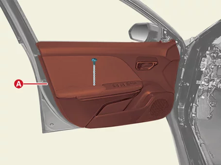
|
| 5.
|
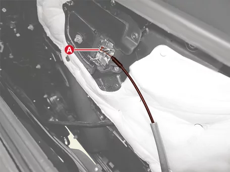
Separate the door latch cable (A).
|
| 6.
|
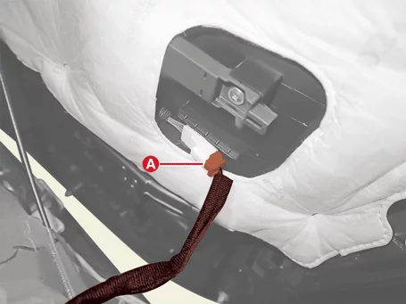
Disconnect the mood lamp connector (A).
|
| 7.
|
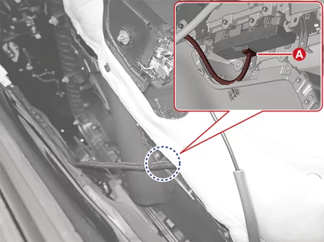
Disconnect the power window switch connector (A).
|
| 8.
|
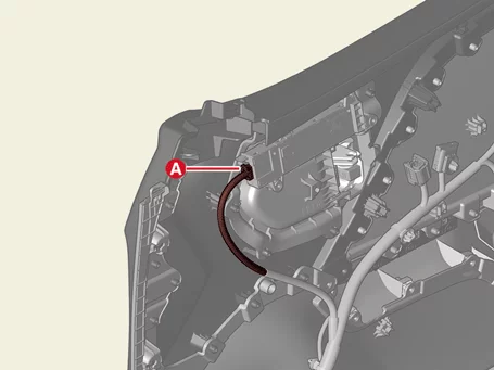
Disconnect the Integrated Memory Seat (IMS) switch connector (A).
|
Door Trim Seal
| 2.
|
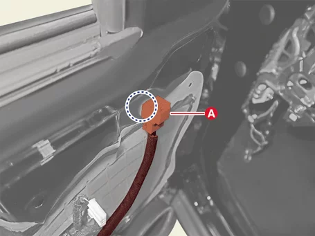
Separate the outside mirror connector wiring (A).
|
| 3.
|
Disconnect the speaker connector (A).
|
| 4.
|
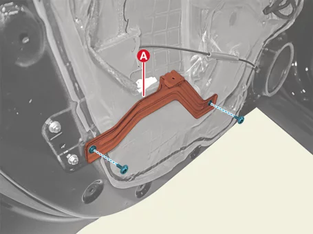
Remove the bracket (A) after removing the screws.
|
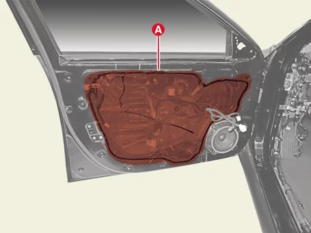
| 5.
|
Remove the seal (A).
|
| 1.
|
Install in the reverse order of removal.
|
Front Door Weather Strip Removal and Installation
|
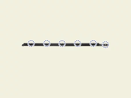
The indication below represents the location of a clip or fastener.
|
Body Side Weather Strip
| 1.
|
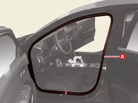
Remove the weather strip (A).
|
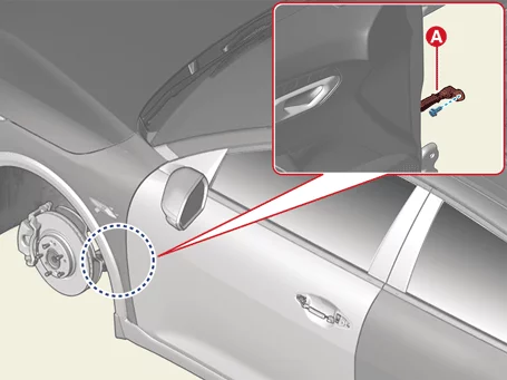
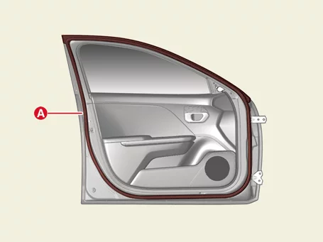
Door Side Weather Strip
| 1.
|
Separate the door checker (A) after removing the bolt.
|
Tightening torque :
21.6 - 32.4 N·m (2.2 - 3.3 kgf·m, 15.9 - 23.9 lb·ft)
|
|
| 2.
|
Remove the weather strip (A).
|
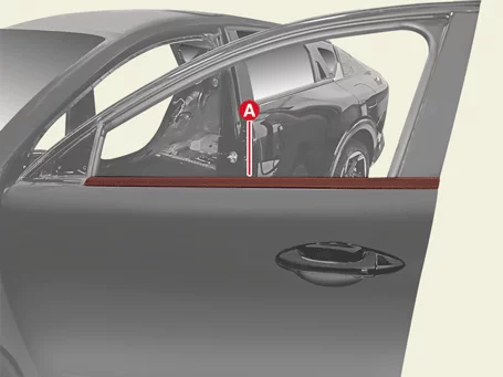
Outside Door Belt Weather Strip
| 1.
|
Remove the outside mirror assembly.
(Refer to Mirror - "Outside Mirror Assembly")
|
| 2.
|
Remove the weather strip (A).
|
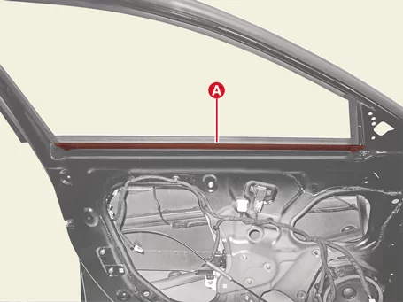
Inside Door Belt Weather Strip
| 1.
|
Remove the front door trim.
(Refer to Front Door - "Front Door Trim")
|
| 2.
|
Remove the weather strip (A).
|
| 1.
|
Install in the reverse order of removal.
|