Contents:
Carrier Assembly Removal and Installation
Carrier Assembly
| 1.
|
Drain the coolant.
(Refer to Engine Mechanical System - "Coolant")
|
| 2.
|
Remove the cooling fan.
(Refer to Engine Mechanical System - "Cooling Fan")
|
| 3.
|
Remove the condenser.
(Refer to Heating,Ventilation And Air Conditioning -
"Condenser")
|
| 4.
|
Remove the hood latch.
(Refer to Hood - "Hood Latch")
|
| 5.
|
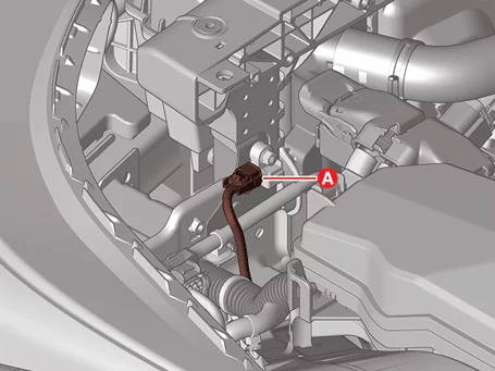
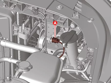
Disconnect the Front Impact Sensor (FIS) connector (A).
Driver's Side
Passenger's Side
|
| 6.
|
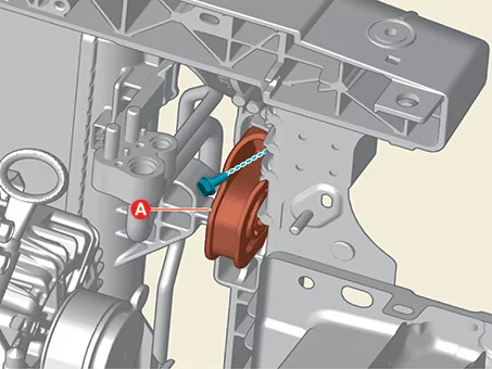
Remove the radiator side mounting bracket (A) after removing the bolts.
|
Tightening torque:
7.8 - 11.8 N·m (0.8 - 1.2 kgf·m, 5.8 - 8.7 lb·ft)
|
Driver's Side
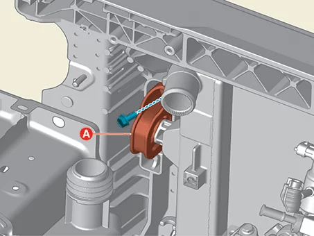
Passenger's Side
|
| 7.
|
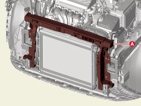
Remove the carrier assembly (A).
|
| 1.
|
Install in the reverse order of removal.
|
Front Bumper Beam Removal and Installation
|
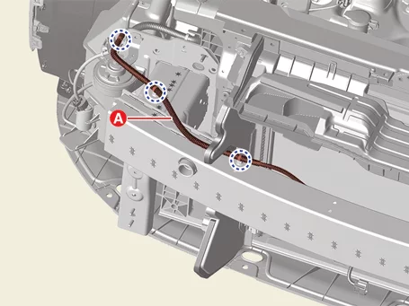
The indication below represents the location of a clip or fastener.

|
| 1.
|
Remove the front bumper stiffener.
(Refer to Front & Rear Bumper - "Front Bumper
Assembly")
|
| 2.
|
Remove the front radar.
(Refer to Advanced Driver Assistance System (ADAS) - "Front
Radar")
|
| 3.
|
Remove the horn.
(Refer to Front End Module - "Horn")
|
| 4.
|
Remove the ambient temperature sensor.
(Refer to Air Conditioning System - "Ambient Temperature
Sensor")
|
| 5.
|
Separate the front bumper beam wiring (A).
|
| 6.
|
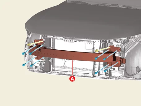
Remove the front bumper beam assembly (A) after removing the bolts and nuts.
|
Tightening torque
Bolt : 21.6 - 26.5 N·m (2.2 - 2.7 kgf·m,
15.9 - 19.5
lb·ft)
Nut : 3.9 - 5.9 N·m (0.4 - 0.6 kgf·m,
2.9 - 4.3 lb·ft,
34.7 - 52.1 lb·in)
|
|
| 1.
|
Install in the reverse order of removal.
|
Horn Removal and Installation
|
The indication below represents the location of a clip or fastener.
|
Horn
| 1.
|
Remove the head lamp.
(Refer to Light & Vision System - "Head Lamp")
|
| 2.
|
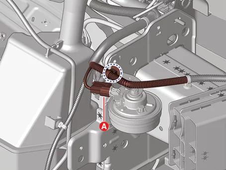
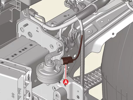
Disconnect the horn connector (A).
Low Pitch
High Pitch
|
| 3.
|
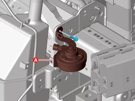
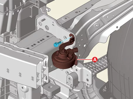
Remove the horn (A) after removing the bolt.
|
Tightening torque:
11.0 - 12.2 N·m (1.12 - 1.24 kgf·m, 8.1 - 9.0 lb·ft)
|
Low Pitch
High Pitch
|
Burglar Alarm
| 1.
|
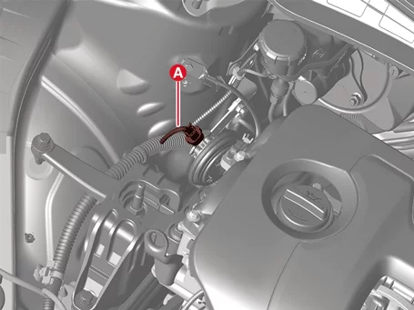
Disconnect the burglar alarm connector (A).
|
| 2.
|
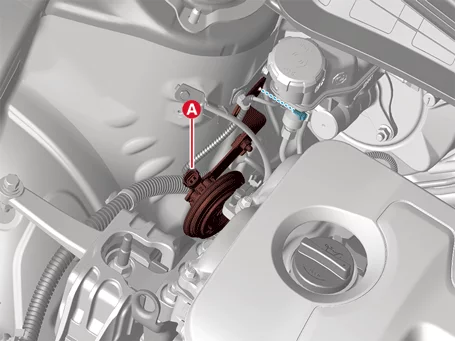
Remove the burglar alarm (A) after removing the bolt.
|
Tightening torque:
11.0 - 12.2 N·m (1.12 - 1.24 kgf·m, 8.1 - 9.0 lb·ft)
|
|
| 1.
|
Install in the reverse order of removal.
|
Other information:
Kia K4 (CL4) 2025-2026 Service Manual: Highway Driving Assist (HDA):
Highway Driving Assist
The Highway Driving Assist (HDA) system in your Kia K4 is designed to detect lane markings and lead vehicles. It actively assists in maintaining a safe following distance, adhering to your set speed, and centering the Kia K4 within its lane while driving on supported highways.
Kia K4 (CL4) 2025-2026 Service Manual: Closing the fuel filler door
To install the fuel tank cap, place it onto the filler neck and rotate it in a clockwise direction until you hear a distinct clicking sound, indicating it is properly sealed for your Kia K4.
Close the exterior fuel filler door by pressing firmly on its rear center edge until the locking mechanism engages and sits flush with the body panel of your Kia K4.