Contents:
Antenna Removal and Installation
Crash Pad Antenna
| 1.
|
Remove the crash pad assembly.
(Refer to Crash Pad - "Crash Pad Assembly")
|
| 2.
|
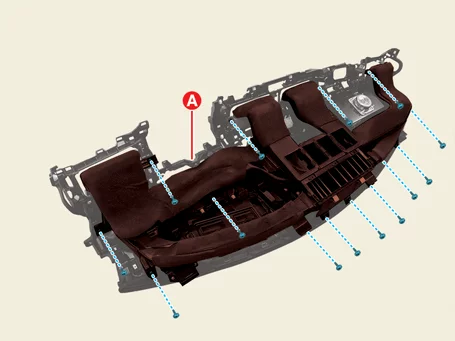
Remove the crash pad air vent duct assembly (A) after removing the screws.
|
| 3.
|
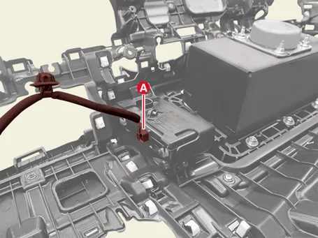
Remove the antenna connector (A).
|
| 4.
|
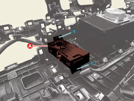
Remove the antenna (A) after removing the screws.
|
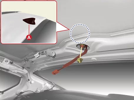
Roof Shark Fin Antenna
| 1.
|
Remove the roof trim assembly.
(Refer to Roof Trim - "Roof Trim Assembly")
|
| 2.
|
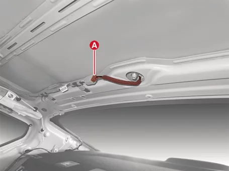
Disconnect the antenna connector (A).
|
| 3.
|
Remove the antenna (A) after removing the nut.
|
Tightening torque :
7.8 - 14.7 N·m (0.8 - 1.5 kgf·m, 5.8 - 10.8 lb·ft)
|
|
| 1.
|
Install in the reverse order of removal.
|
Cluster Unit On Vehicle Inspection
| 1.
|
The cluster unit can quickly diagnosed for problems with KDS. (Refer to "DTC guide")
| (1)
|
Self diagnosis : Inspect the Diagnostic Trouble Code (DTC) with the KDS.
(Refer to DTC guide when fault code is found)
|
| (2)
|
S/W Management : Controlling other features including system option setting and
zero point
adjustment.
(S/W Management → Cluster Module → CLU Variant Coding)
|
|
Refer to the KDS screen for operating conditions and details.
|
|
Cluster Unit Removal and Installation
Cluster Unit
| 1.
|
Remove the integrated monitor.
(Refer to Infotainment System - "Integrated Monitor")
|
| 2.
|
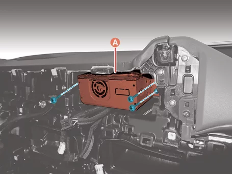
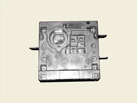
Remove the unit (A) after removing the screws.
|
| 3.
|
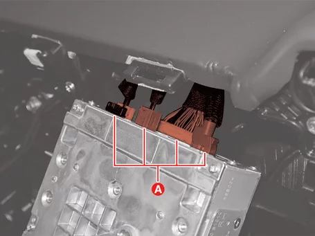
Disconnect the unit connectors (A).
|
| 1.
|
Install in the reverse order of removal.
|
| 2.
|
Perform the order below with the KDS when replacing the cluster unit.
(S/W Management → Cluster Module → CLU Variant Coding)
|
Refer to the KDS screen for operating conditions and details.
|
|
| 3.
|
Perform Over The Air (OTA) controller S/W update with KDS.
(Refer to Security & Vehicle Ignition System - "Over The
Air
(OTA)")
|
Connected Car Navigation Cockpit (ccNC) On Vehicle Inspection
| 1.
|
The Connected Car Navigation Unit (ccNC) can quickly diagnosed for problems with the KDS.
(Refer to "DTC
guide")
| (1)
|
Self diagnosis : Inspect the Diagnostic Trouble Code (DTC) with the KDS.
(Refer to DTC guide when fault code is found.)
|
| (2)
|
S/W Management : Controlling other features including system option setting and
zero point
adjustment.
(S/W Management → Connected Car Navigation Cockpit → HUD Calibration)
(S/W Management → Connected Car Navigation Cockpit → AVN/Audio Diagnostic Mode)
(S/W Management → Connected Car Navigation Cockpit → AVN-FPM Learning Mode)
(S/W Management → Connected Car Navigation Cockpit → AVN-FPM Neutralization
Mode)
(S/W Management → Connected Car Navigation Cockpit → ESC Variant Coding)
|
|
Refer to the KDS screen for operating conditions and details
|
|
Connected Car Navigation Cockpit (ccNC) Removal and Installation
Connected Car Navigation Cockpit (ccNC)
| 1.
|
Remove the crash pad center panel.
(Refer to Crash Pad - "Crash Pad Panel")
|
| 2.
|
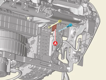
Remove the bracket (A) after removing the bolt and nut.
|
Tightening torque:
6.9 - 10.8 N·m (0.7 - 1.1 kgf·m, 5.1 - 8.0 lb·ft)
|
|
| 3.
|
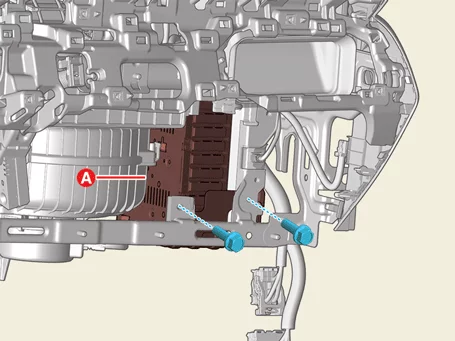
Remove the unit (A) after removing the bolts.
|
Tightening torque:
6.9 - 10.8 N·m (0.7 - 1.1 kgf·m, 5.1 - 8.0 lb·ft)
|
|
| 4.
|
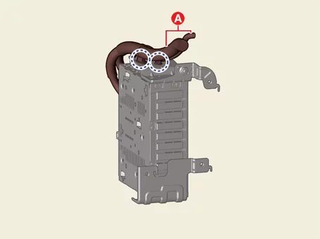
Separate the connector wiring (A) after removing the clips.
|
| 5.
|
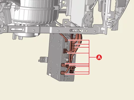
Disconnect the unit connectors (A).
|
| 1.
|
Install in the reverse order of removal.
|
| 2.
|
Perform the order below with the KDS when replacing the Connected Car Navigation Cockpit
(ccNC).
(S/W Management → Connected Car Navigation Cockpit → ESC Variant Coding)
(S/W Management → Rear View Monitor → Variant Coding)
|
Refer to the KDS screen for operating conditions and details.
|
|
| 3.
|
Perform Over The Air (OTA) controller S/W update with KDS.
(Refer to Security & Vehicle Ignition System - "Over The
Air
(OTA)")
|
External AMP On Vehicle Inspection
Diagnosis with KDS
| 1.
|
The external amplifier can quickly diagnosed for problems with KDS. (Refer to "DTC guide")
| (1)
|
Self diagnosis : Inspect the Diagnostic Trouble Code (DTC) with the KDS.
(Refer to DTC guide when fault code is found)
|
| (2)
|
S/W Management : Controlling other features including system option setting and
zero point
adjustment.
(S/W Management → Amplifier → AMP Operation Test)
|
|
Refer to the KDS screen for operating conditions and details.
|
|
External AMP Removal and Installation - 4DR
| 1.
|
Remove the luggage side trim. [Passenger's side]
(Refer to Luggage Trim - "Luggage Side Trim")
|
| 2.
|
Disconnect the external amplifier connectors (A).
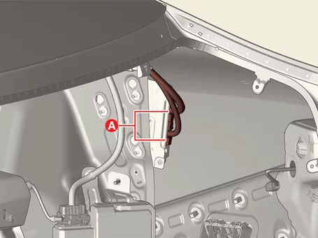
|
| 3.
|
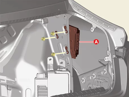
Remove the external amplifier (A) after removing the nuts.
|
Tightening torque:
1.5 - 2.0 N·m (0.15 - 0.20 kgf·m, 1.1 - 1.4 lb·ft, 13.0 - 17.4 lb·in)
|
|
| 1.
|
Install in the reverse order of removal.
|
| 2.
|
Perform Over The Air (OTA) controller S/W update with KDS.
(Refer to Security & Vehicle Ignition System - "Over The
Air
(OTA)")
|
External AMP Removal and Installation - 5DR
| 1.
|
Remove the luggage side trim. [Passenger's side]
(Refer to Luggage Trim - "Luggage Side Trim")
|
| 2.
|
Disconnect the external amplifier connectors (A).
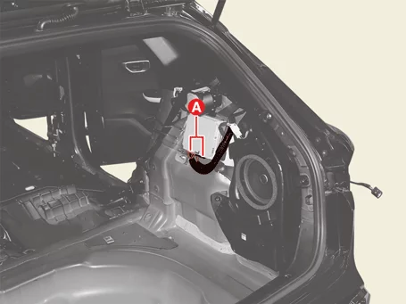
|
| 3.
|
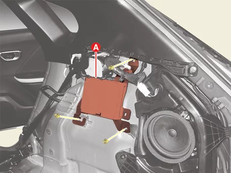
Remove the external amplifier (A) after removing the nuts.
|
Tightening torque:
1.5 - 2.0 N·m (0.15 - 0.20 kgf·m, 1.1 - 1.4 lb·ft, 13.0 - 17.4 lb·in)
|
|
| 1.
|
Install in the reverse order of removal.
|
| 2.
|
Perform Over The Air (OTA) controller S/W update with KDS.
(Refer to Security & Vehicle Ignition System - "Over The
Air
(OTA)")
|
Infotainment Keyboard On Vehicle Inspection
| 1.
|
The infotainment keyboard can quickly diagnosed for problems with the KDS. (Refer to "DTC
guide")
| (1)
|
Self diagnosis : Inspect the Diagnostic Trouble Code (DTC) with the KDS.
(Refer to DTC guide when fault code is found)
|
|
Refer to the KDS screen for operating conditions and details.
|
|
Infotainment Keyboard Removal and Installation
| 1.
|
Remove the crash pad upper garnish. [Passenger's side]
(Refer to Crash Pad - "Crash Pad Garnish")
|
| 2.
|
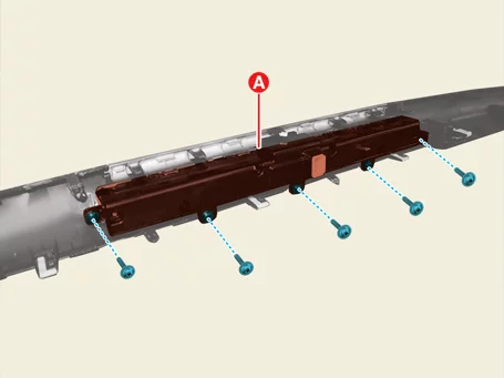
Remove the infotainment keyboard (A) after removing the screws.
|
| 1.
|
Install in the reverse order of removal.
|
| 2.
|
Perform Over The Air (OTA) controller S/W update with KDS.
(Refer to Security & Vehicle Ignition System - "Over The
Air
(OTA)")
|
Instrument Cluster Removal and Installation
|
When the instrument cluster is applied to the vehicle, the cluster unit is not included.
|
| 1.
|
Remove the crash pad air vent. [Driver's side]
(Refer to Crash Pad - "Crash Pad Air Vent")
|
| 2.
|
Remove the crash pad upper garnish. [Passenger's side]
(Refer to Crash Pad - "Crash Pad Garnish")
|
| 3.
|
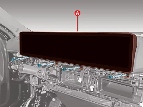
Remove the instrument cluster (A) after removing the screws.
|
| 4.
|
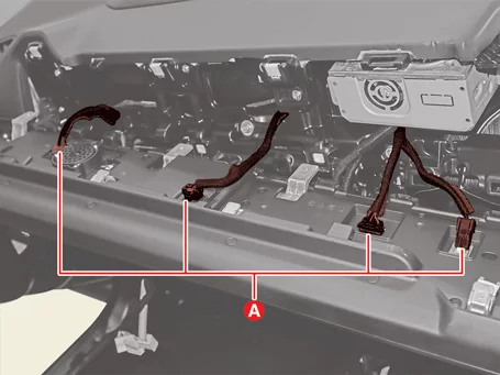
Disconnect the instrument cluster connectors (A).
|
| 1.
|
Install in the reverse order of removal.
|
| 2.
|
Perform the order below with the KDS when replacing the instrument cluster.
(S/W Management → Cluster Module → CLU Variant Coding)
|
Refer to the KDS screen for operating conditions and details.
|
|
| 3.
|
Perform Over The Air (OTA) controller S/W update with KDS.
(Refer to Security & Vehicle Ignition System - "Over The
Air
(OTA)")
|
Integrated Monitor Removal and Installation
|
When the integrated monitor is applied to the vehicle, the cluster unit is included.
|
| 1.
|
Remove the crash pad air vent. [Driver's side]
(Refer to Crash Pad - "Crash Pad Air Vent")
|
| 2.
|
Remove the crash pad upper garnish. [Passenger's side]
(Refer to Crash Pad - "Crash Pad Garnish")
|
| 3.
|
Remove the integrated monitor (A) after removing the screws.
|
| 4.
|
Disconnect the integrated monitor connectors (A).
|
| 1.
|
Install in the reverse order of removal.
|
Mic Removal and Installation
|
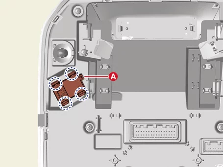
The indication below represents the location of a clip or fastener.

|
| 1.
|
Remove the overhead console lamp.
(Refer to Light & Vision System - "Overhead Console
Lamp")
|
| 2.
|
Remove the mic (A).
|
| 1.
|
Install in the reverse order of removal.
|
Mic Inspection
| 1.
|
Remove the overhead console lamp.
(Refer to Light & Vision System - "Overhead Console
lamp")
|
| 2.
|
Check the continuity of between terminals.
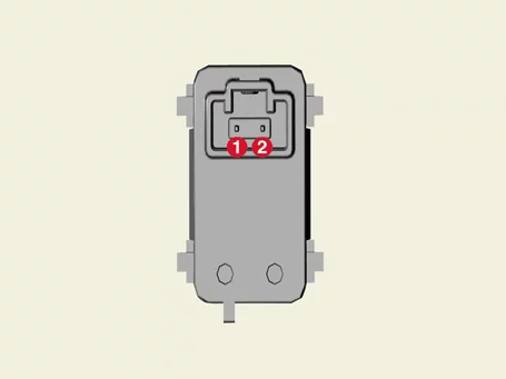
|
| 1.
|
Remove the floor console bezel.
(Refer to Floor Console - "Floor Console Assembly")
|
| 2.
|
Remove the multimedia jack (A).
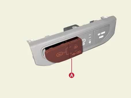
|
| 1.
|
Install in the reverse order of removal.
|
Speaker Removal and Installation
Front Center Speaker
| 1.
|
Remove the center speaker grille.
(Refer to Crash Pad - "Crash Pad Cover")
|
| 2.
|
Remove the speaker (A) after removing the screws.
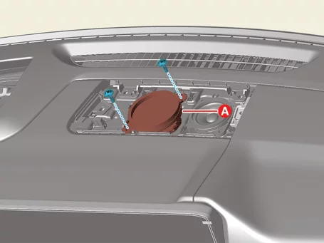
|
| 3.
|
Disconnect the speaker connector (A).
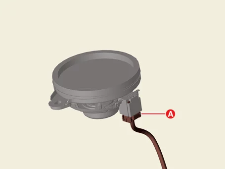
|
Emergency Call Speaker
| 1.
|
Remove the center speaker grille.
(Refer to Crash Pad - "Crash Pad Cover")
|
| 2.
|
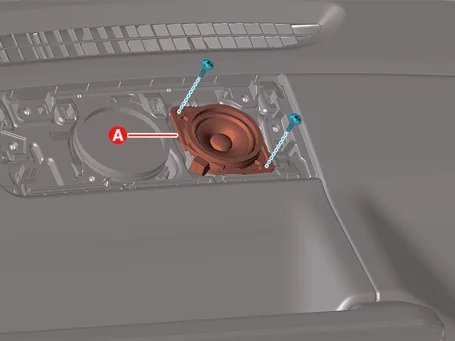
Remove the speaker (A) after removing the screws.
|
| 3.
|
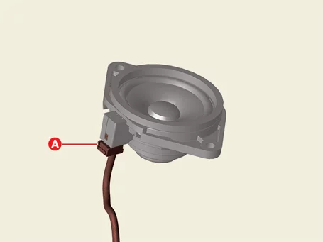
Disconnect the speaker connector (A).
|
Tweeter Speaker
| 1.
|
Remove the front pillar trim.
(Refer to Interior Trim - "Front Pillar Trim")
|
| 2.
|
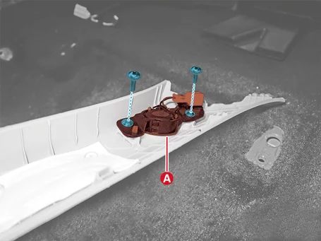
Remove the speaker (A) after removing the screws.
|
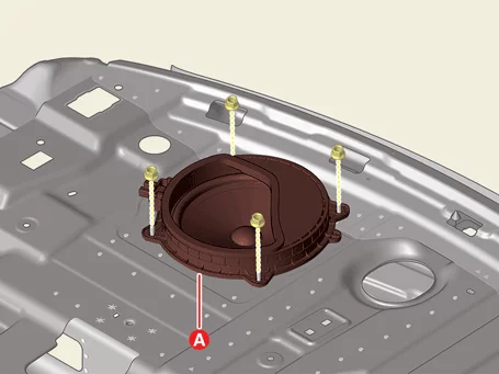
Subwoofer Speaker [4DR]
| 1.
|
Remove the package tray trim.
(Refer to Luggage Trim - "Package Tray Trim")
|
| 2.
|
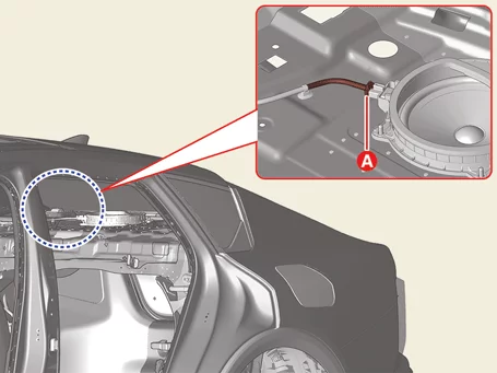
Disconnect the speaker connector (A).
|
| 3.
|
Remove the speaker (A) after removing the nuts.
|
Tightening torque:
1.5 - 2.0 N·m (0.15 - 0.20 kgf·m, 1.1 - 1.4 lb·ft, 13.0 - 17.4 lb·in)
|
|
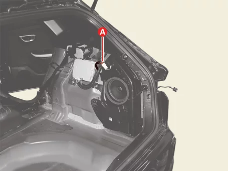
Subwoofer Speaker [5DR]
| 1.
|
Remove the luggage side trim. [Passenger's side]
(Refer to Luggage Trim - "Luggage Side Trim")
|
| 2.
|
Disconnect the speaker connector (A).
|
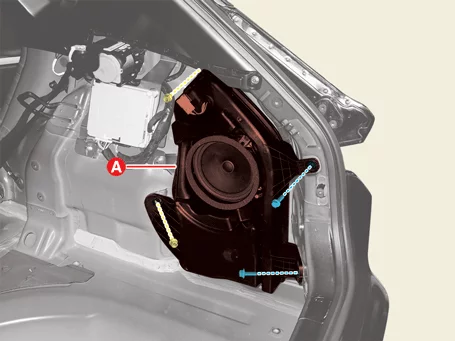
| 3.
|
Remove the speaker (A) after removing the bolts and nuts.
|
Tightening torque:
1.5 - 2.0 N·m (0.15 - 0.20 kgf·m, 1.1 - 1.4 lb·ft, 13.0 - 17.4 lb·in)
|
|
| 1.
|
Install in the reverse order of removal.
|
Speaker Inspection
Basic Inspection
| 1.
|
Remove the speaker by removing the screws to prevent interference with the body trim and
surrounding
parts.
|
| 2.
|
After removing the speaker, check the sound quality of the speaker with the connector plugged
in.
|
Individual Inspection
| 1.
|
Abnormal vibration
| (1)
|
Make sure the mounting screws are properly tightened before replacing the
speaker.
|
| (2)
|
Reinstall the speaker and check that the symptom is resolved.
|
| (3)
|
If the symptom does not disappear, replace the speaker with a new one.
|
|
| 2.
|
Noise
| (1)
|
Check that the speaker connector is properly connected and reinstall the
connector if necessary.
|
–
|
If noises occur in radio mode, turn to the media player mode.
|
|
–
|
If noises occur in both modes, replace the speaker with a new
one.
|
|
If noises occur only in the radio mode, the poor radio
reception is the cause so do not
replace the speaker.
|
|
|
| 3.
|
Malfunctions
|
–
|
Check the plus ( + ) and negative ( - ) speaker terminals using an ohmmeter.
|
|
Speaker Troubleshooting
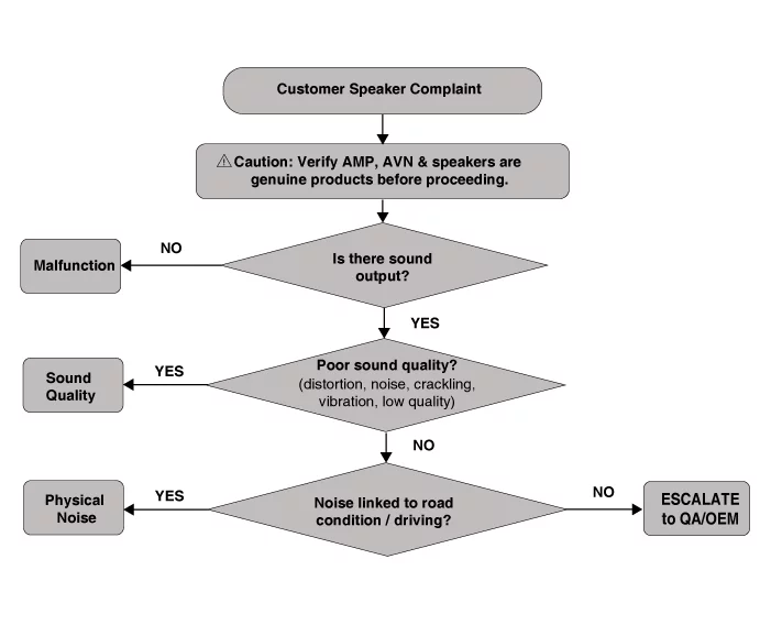
| Speaker Malfunction (No sound / Abnormal Output) |
| 1.
|
Check for symptom reproduction
| (1)
|
Is there no sound from one or all speakers?
Item
|
Correction
|
Yes
|
Check the connector condition and the wiring condition.
(Refer to "Inspection
2")
|
No
|
It is determined to be a temporary issue with related parts, and it
is currently judged to be
normal.
|
|
|
| 2.
|
Check for connector condition
| (1)
|
Is the connector is correctly connected?
|
Item
|
Correction
|
Yes
|
Measure voltage at the speaker connector. (Measure after approximately 10 minutes in
sleep mode after
IG OFF)
|
No
|
Reconnect the connector and perform retest.
|
|
| 3.
|
Measure voltage at speaker connector
| (1)
|
Are the port and output voltage is correct?
Item
|
Correction
|
Yes
|
Check the AMP, AVN, and wiring harness. (Avoid recurring
failures)
|
No
|
When there is no voltage and the condition is normal, replace the
speaker.
|
|
|
Poor sound quality (Noise, distortion)
| 1.
|
Check for symptom reproduction
| (1)
|
Is the speaker sound quality abnormal? (Noise, distortion, crackling, noise at
high/low volume,
and noise with specific audio sources)
Item
|
Correction
|
Yes
|
Check for loose objects (door trim, cup holder, etc.)
and perform the diagnostic
steps.
|
No
|
Confirm the issue using different sources (radio, BT, USB).
|
|
|
| 2.
|
Perform the diagnostic steps
| (1)
|
High volume noise:
|
–
|
Check if noise is caused by vibration, not speaker.
|
|
–
|
If the noise disappears when the volume is reduced, the speaker
is normal.
|
|
| (2)
|
Source check:
|
–
|
Test the same content via different sources.
|
|
–
|
If the issue occurs only with one source, the speaker is
normal.
|
|
| (3)
|
Speaker individual check:
|
–
|
Check each speaker individually.
|
|
–
|
If noise occurs from only one source, the speaker is abnormal.
|
|
–
|
If noise occurs from all sources, check the AMP or the wiring.
|
|
| (4)
|
Bass Vibration:
|
–
|
Remove objects causing vibration (trim parts, etc.).
|
|
–
|
If noise disappears, the speaker is normal.
|
|
| (5)
|
Decision:
|
–
|
Replace the speaker ONLY if the issue constantly occurs across
all sources.
|
|
–
|
Otherwise, check the source, vehicle components, and wiring.
|
|
|
Physical / Road noise
| 1.
|
Check for symptom reproduction
| (1)
|
Is there noise from the speaker when driving over speed bumps or rough roads?
Item
|
Correction
|
Yes
|
Confirm that noise occurs only during driving and
identify the noise type (rattle,
interference, etc.). Check if the noise changes with road conditions
and perform diagnostic
steps.
|
No
|
Confirm issue with different sources (suspension, driveshaft,
stabilizer).
|
|
|
| 2.
|
Perform diagnostic steps
| (1)
|
Test Drive:
|
–
|
Reproduce the noise on rough roads or over speed bumps.
|
|
–
|
Identify the accurate location and type of noise.
|
|
| (2)
|
Noise classification:
|
–
|
Rattle: likely caused by the door latch, trim, or trunk.
|
|
–
|
Interference: likely caused by the underbody components.
|
|
| (3)
|
Isolation check:
|
–
|
Check the suspension and underbody parts.
|
|
–
|
Inspect the door latch, striker, and trunk catch.
|
|
–
|
When noise occurs with all sources (radio, BT, USB), check the
AMP and the wiring.
|
|
| (4)
|
Decision:
|
–
|
If noise is caused by vehicle components, the speaker is
normal.
|
|
–
|
Repair or adjust the related mechanical components.
|
|
|
Steering Wheel Remote Controller On Vehicle Inspection
| 1.
|
The steering wheel remote control can quickly diagnosed for problems with KDS. (Refer to "DTC
guide")
| (1)
|
Self diagnosis : Inspect the Diagnostic Trouble Code (DTC) with the KDS.
(Refer to DTC guide when fault code is found)
|
|
Refer to the KDS screen for operating conditions and details.
|
|
Steering Wheel Remote Controller Removal and Installation
| 1.
|
Remove the Steering Wheel Remote Controller (SWRC) switches.
(Refer to Steering System - "Steering Wheel")
|
| 1.
|
Install in the reverse order of removal.
|
Other information:
Kia K4 (CL4) 2025-2026 Service Manual: Tires and wheels
For consistent vehicle performance, long-term safety, and optimal fuel economy, it is essential that you always maintain the recommended tire pressures and operate the Kia K4 within the specified load limits and weight distribution guidelines.
Recommended cold tire inflation pressures
For the most accurate readings, check all tire pressures while the tires are "cold.
Kia K4 (CL4) 2025-2026 Service Manual: Lane Following Assist (LFA)
The Lane Following Assist (LFA) system is a sophisticated driver-assistance feature designed to enhance your comfort and safety. By utilizing advanced sensor technology, the Kia K4 can actively detect lane markings or the position of a vehicle traveling directly ahead. The system then provides subtle steering support to help keep your Kia K4 centered within its lane, significantly reducing driver fatigue during long journeys or highway driving.