Contents:
Fluid Inspection
|
•
|
This video was created using 3D graphics to help understand the vehicle
maintenance manual.
|
|
•
|
There may be some differences from actual vehicles.
|
|
•
|
The location and repair procedures of the parts may vary depending on vehicle
model, model year,
region, and specifications.
|
|
•
|
Check the KDS Guide for detailed information on how to use the KDS.
|
|
•
|
Check the manual for detailed maintenance procedures.
|
|
•
|
Unauthorized reproduction, distribution, or sharing of this video is
prohibited.
|
|
Automatic Transaxle Fluid (ATF) Level Check
(Click to play)

Video: Automatic Transaxle Fluid (ATF) Level
Check
Inspect the Automatic Transaxle Fluid (ATF) level
|
When checking the ATF level, be careful not to allow foreign substance (like dust) to enter
through the
filler hole.
|
| 1.
|
Remove the air cleaner assembly.
(Refer to Engine Mechanical System - "Air Cleaner")
|
| 2.
|
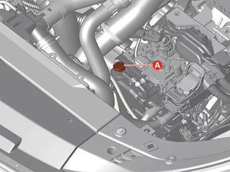
Add 0.7 ℓ of ATF SP4M-1 through the ATF filler hole after removing the eyebolt (A).
|
Recommended : ATF SP4M-1
The list of automatic transaxle fluid approved
by Kia : SK
ATF SP4M-1, MICHANG ATF SP4M-1, S-OIL ATF SP4M-1, Kia Genuine ATF SP4M-1
|
|
•
|
If the genuine oil that is developed for best performance is
not used, it may cause
performance or problems with transaxle.
|
|
•
|
The use of non-specified oil could even result in shift quality
deterioration and
vibrations, eventually, transaxle failure.
|
|

Automatic Transaxle Fluid (ATF) Level Check Based on Drain Volume (Play ▶)
Video: Automatic Transaxle
Fluid (ATF) Level
Check Based on Drain Volume
Notes When Refering Video
This video provides guidance for understanding complex or hard-to-follow procedures by showing
each step
clearly.
As needed, the video also provides clear guidance on essential procedural steps, including
adjustment
and diagnostic processes, the use of SSTs, and precautions to avoid component damage.
|
•
|
This video is created using common specifications and may differ from the
actual vehicle.
|
|
•
|
The location and repair procedures of the parts may vary depending on vehicle
model, model year,
region, and specifications.
|
|
•
|
Check the KDS guide for detailed information on how to use the KDS.
|
|
•
|
Check the manual for detailed maintenance procedures.
|
|
•
|
Unauthorized reproduction, distribution, or sharing of this video is
prohibited.
|
|
| 3.
|
Start the engine to warm up the ATF.
|
Do not step on the brake and accelerator simultaneously to warm up the ATF.
|
|
| 4.
|
Check using KDS that the temperature of the ATF is between 50 - 60°C (122 - 140°F).
|
| 5.
|
Move the shift lever slowly from "P" to "D", then back to "P". Repeat this sequence two times
and then
move the shift lever to "P" range.
|
Pause in each range for more than 2 seconds.
|
|
| 6.
|
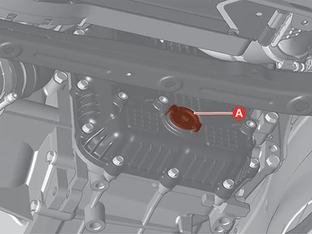
Remove the ATF level plug (A).
|
When removing the ATF level plug, keep the vehicle on a level ground.
|
|
| 7.
|
Check the ATF level.
|
Normal : ATF flows out in a thin oil
stream.
Excessive : Over 0.9 liters of ATF flows
out for 2
minutes.
Insufficient : There is no fluid flow.
|
If the ATF level is too high or low, follow the
instructions
below.
|
•
|
Excessive : Drain until the ATF flows out in a thin oil stream.
|
|
•
|
Insufficient : Add until the ATF flows out in a thin oil
stream.
|
|
|
| 8.
|
Install the ATF level plug (A).
|
| 9.
|
Lower the vehicle and install the ATF eyebolt (A).
|
Tightening torque :
4.9 - 5.9 N·m (0.5 - 0.6 kgf·m, 3.6 - 4.3 lb·ft, 43.4 - 52.1 lb·in)
|
|
| 10.
|
Install the air cleaner assembly.
(Refer to Engine Mechanical System - "Air Cleaner")
|
Fluid Replacement
| 1.
|
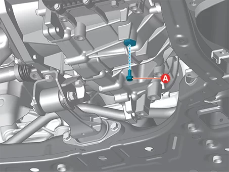
Remove the ATF drain plug (A), allow the fluid to drain out and then reinstall the drain plug.
|
Tightening torque :
33.3 - 43.1 N·m (3.4 - 4.4 kgf·m, 24.6 - 31.8 lb·ft)
|
|
The existing drain plug gasket must be replaced with a new one (do not reuse).
|
|
| 2.
|
Remove the air cleaner assembly.
(Refer to Engine Mechanical System - "Air Cleaner")
|
| 3.
|
Remove the ATF eyebolt (A).
|
| 4.
|
Fill about 5.0 ℓ of the ATF SP4M-1 through the ATF filler hole.
|
Recommended : ATF SP4M-1
The list of automatic transaxle fluid approved
by Kia : SK
ATF SP4M-1, MICHANG ATF SP4M-1, S-OIL ATF SP4M-1, Kia Genuine ATF SP4M-1
|
|
•
|
If the genuine oil that is developed for best performance is
not used, it may cause
performance or problems with transaxle.
|
|
•
|
The use of non-specified oil could even result in shift quality
deterioration and
vibrations, eventually, transaxle failure.
|
|
|
| 5.
|
Perform the ATF level check procedure.
(Refer to Fluid - "Inspection")
|
| 6.
|
Lower the vehicle and install the ATF eyebolt (A).
|
Tightening torque :
4.9 - 5.9 N·m (0.5 - 0.6 kgf·m, 3.6 - 4.3 lb·ft, 43.4 - 52.1 lb·in)
|
|
| 7.
|
Install the air cleaner assembly.
(Refer to Engine Mechanical System - "Air Cleaner")
|
Valve Body Components and Components Location
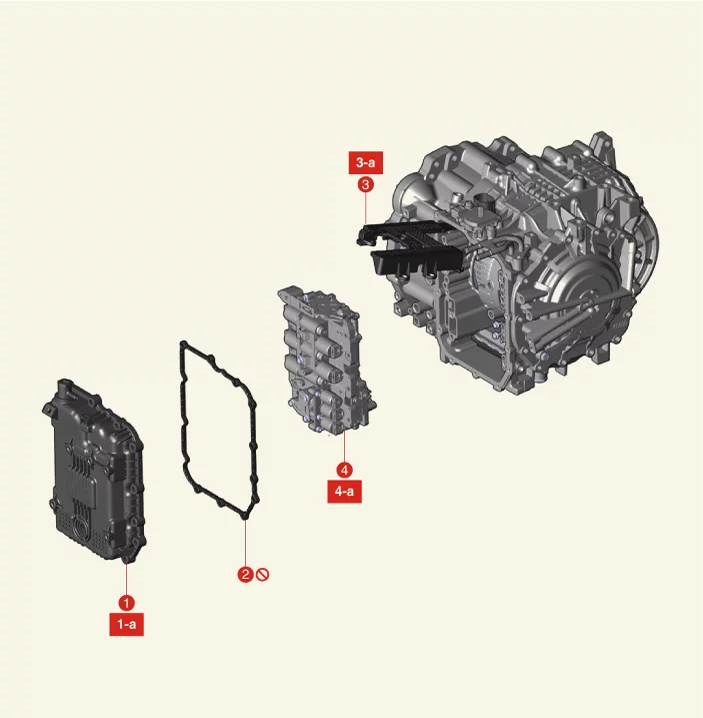
1. Valve Body
Cover
1-a.
11.8 - 13.7 N·m (1.2 - 1.4 kgf·m, 8.7 - 10.1 lb·ft)
2. Valve Body Cover Gasket
|
3. E Module
3-a. 9.8 - 11.8 N·m (1.0 - 1.2
kgf·m,
7.2 - 8.7 lb·ft)
4. Valve Body
4-a. 9.8 - 11.8 N·m (1.0 - 1.2 kgf·m, 7.2 - 8.7 lb·ft)
|
Valve Body Description and Operation
|
•
|
The valve body is a mandatory component of automatic transaxle control and has various valves
that
control the fluid supplied from the oil pump.
|
|
•
|
There is a regulator valve that regulates pressure, a switching valve that changes the
direction of oil,
a shift valve that performs shifting, and a manual valve connected to a shift lever.
|
|
•
|
The electronic solenoid valve is mounted in the valve body to provide the best performance of
shift.
|
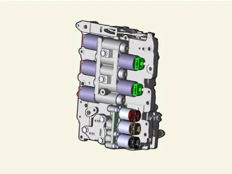
Valve Body Removal
|
•
|
This video was created using 3D graphics to help understand the vehicle
maintenance manual.
|
|
•
|
There may be some differences from actual vehicles.
|
|
•
|
The location and repair procedures of the parts may vary depending on vehicle
model, model year,
region, and specifications.
|
|
•
|
Check the KDS Guide for detailed information on how to use the KDS.
|
|
•
|
Check the manual for detailed maintenance procedures.
|
|
•
|
Unauthorized reproduction, distribution, or sharing of this video is
prohibited.
|
|
Valve Body Removal
(Click to play)
Video: Valve Body Removal
|
•
|
Maintain clean condition so that foreign substance does not get into the
automatic transaxle.
|
|
•
|
Use a coated apron, latex gloves, and stainless tray to prevent foreign
substances from entering
the internal part of the automatic transaxle.
|
|
•
|
Automatic transaxle is composed of delicate components. Be careful not to cause
any damage on the
component when assembling and disassembling.
|
|
| 1.
|
Shift the gear to N.
|
Use wheel chocks to prevent vehicle from being moved accidentally.
|
|
| 2.
|
Remove the engine room under cover.
(Refer to Engine Mechanical System - "Engine Room Under
Cover")
|
| 3.
|
Remove the ATF drain plug (A), allow the fluid to drain out and then reinstall the drain plug.
|
Tightening torque :
33.3 - 43.1 N·m (3.4 - 4.4 kgf·m, 24.6 - 31.8 lb·ft)
|
|
•
|
Automatic transaxle fluid (ATF) can be reused. Collect it using
a clean 10 ℓ beaker.
|
|
•
|
The existing ATF drain plug gasket must be replaced with a new
one (do not reuse).
|
|
|
| 4.
|
Disconnect the battery negative ( - ) terminal.
|
| 5.
|
Remove the air cleaner assembly.
(Refer to Engine Mechanical System - "Air Cleaner")
|
| 6.
|
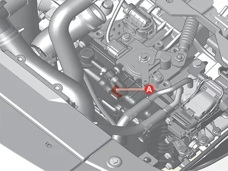
Separate the breather hose clip (A).
|
| 7.
|
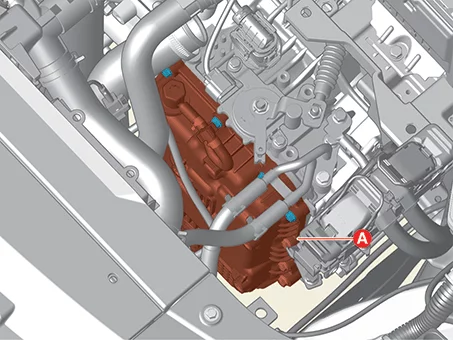
Remove the valve body cover (A) upper bolts.
|
Tightening torque :
11.8 - 13.7 N·m (1.2 - 1.4 kgf·m, 8.7 - 10.1 lb·ft)
|
|
| 8.
|
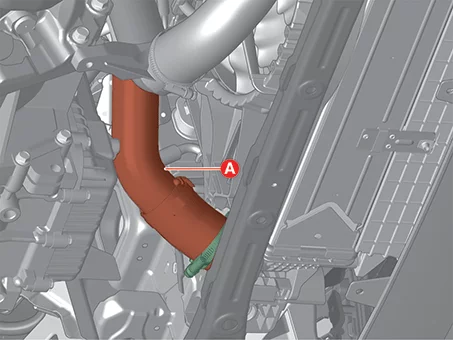
Separate the intercooler hose (A) after removing the clamp.
|
Tightening torque :
4.9 - 6.9 N·m (0.5 - 0.7 kgf·m, 3.6 - 5.1 lb·ft, 43.4 - 60.8 lb·in)
|
|
| 9.
|
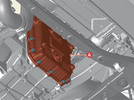
Remove the valve body cover (A) after removing the bolts.
|
Tightening torque :
11.8 - 13.7 N·m (1.2 - 1.4 kgf·m, 8.7 - 10.1 lb·ft)
|
|
Be careful not to spill the remaining ATF when removing the valve body cover.
|
|
| 10.
|
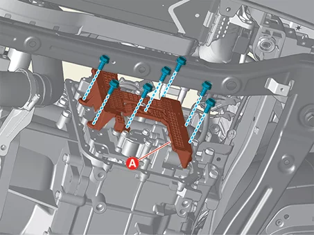
Separate the E module (A) after removing the bolts.
|
Tightening torque :
9.8 - 11.8 N·m (1.0 - 1.2 kgf·m, 7.2 - 8.7 lb·ft)
|
|
| 11.
|
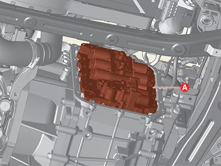
Remove the valve body assembly (A) after removing the bolts.
|
Tightening torque :
9.8 - 11.8 N·m (1.0 - 1.2 kgf·m, 7.2 - 8.7 lb·ft)
|
|
Valve Body Installation
|
•
|
This video was created using 3D graphics to help understand the vehicle
maintenance manual.
|
|
•
|
There may be some differences from actual vehicles.
|
|
•
|
The location and repair procedures of the parts may vary depending on vehicle
model, model year,
region, and specifications.
|
|
•
|
Check the KDS Guide for detailed information on how to use the KDS.
|
|
•
|
Check the manual for detailed maintenance procedures.
|
|
•
|
Unauthorized reproduction, distribution, or sharing of this video is
prohibited.
|
|
Valve Body Installation
(Click to play)
Video: Valve Body Installation
| 1.
|
Install in reverse order of removal.
|
•
|
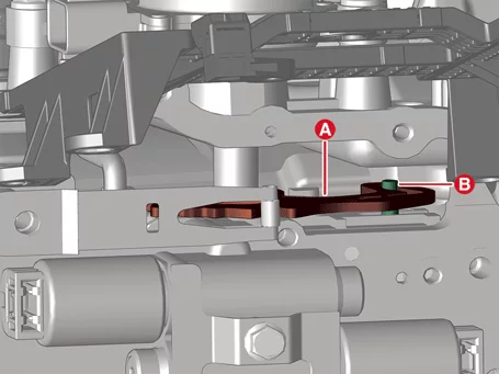
When installing the valve body, make sure that the pin (B) of
the manual valve is
inserted into the detent lever (A).
|
|
•
|
Lubricate the oil temperature sensor O-ring (A) before
installing the E module.
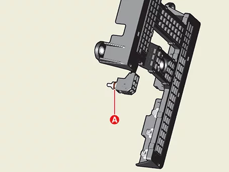
|
|
•
|
When installing, after mounting the E module, lightly tap the
connector part (A) to
insert the connector certainly and then tighten the bolts.
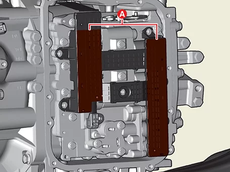
|
|
•
|
The existing valve body cover gasket (A) must be replaced with
a new one (do not reuse).
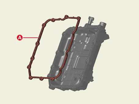
|
|
•
|
When installing the valve body cover, tighten the remaining
bolt after pre-tightening the
bolts (A).
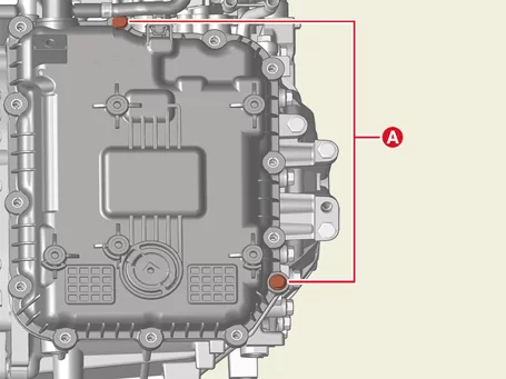
|
|
•
|
If the valve body needs to be replaced the oil pressure
characteristics should be input
using the KDS.
|
|
•
|
If the oil pressure characteristic is not entered, a shift
shock or delay may occur.
|
|
|
| 2.
|
Perform the procedures below after the installation.
| (1)
|
Replenish the automatic transaxle fluid.
(Refer to Hydraulic System - "Fluid")
|
| (2)
|
Clear the diagnostic trouble codes (DTC) using the KDS.
Disconnecting the battery negative terminal will not clear the DTCs. Clear DTCs
using the KDS at
all times.
|
| (3)
|
Perform the resetting automatic transaxle adaptive values using the KDS.
(S/W Management → Automatic Transaxle → Resetting Auto T/A Values)
|
Refer to the KDS screen for operating conditions and details.
|
|
| (4)
|
Perform the oil pressure characteristics input procedure using the KDS.
(S/W Management → Automatic Transaxle → Oil-pressure Characteristics Input)
|
Refer to the KDS screen for operating conditions and details.
|
|
| (5)
|
Perform the TCM adaptive values learning procedure.
(Refer to Automatic Transaxle Control System -
"Adjustment")
|
| (6)
|
After installing, check for leakage of fluid from hose connection during engine
starting and
running.
|
|
28 Brake Control Solenoid Valve (28/B_VFS) Specification
Item
|
Specification
|
Control type
|
Direct control, N/L (Normal Low)
|
Control pressure [kPa (kgf/cm², psi)]
|
0 - 1,569.06 (0 - 16, 0 - 227.57)
|
Control current (mA)
|
0 - 1100
|
Coil resistance (Ω)
|
5.0 - 5.6
|
28 Brake Control Solenoid Valve (28/B_VFS) Components and Components Location
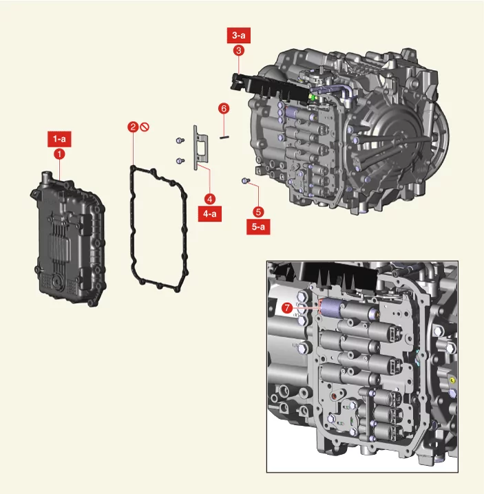
1. Valve Body
Cover
1-a.
11.8 - 13.7 N·m (1.2 - 1.4 kgf·m, 8.7 - 10.1 lb·ft)
2. Valve Body Cover Gasket
3. E
Module
3-a. 9.8 -
11.8 N·m (1.0 - 1.2 kgf·m, 7.2 - 8.7 lb·ft)
|
4. Support Bracket
4-a. 9.8 - 11.8 N·m (1.0
- 1.2
kgf·m, 7.2 - 8.7 lb·ft)
5. Valve Body Bolt
5-a. 9.8 - 11.8 N·m (1.0 - 1.2 kgf·m, 7.2 - 8.7
lb·ft)
6.
Roller
7. 28 Brake Control Solenoid Valve
|
28 Brake Control Solenoid Valve (28/B_VFS) Description and Operation
|
•
|
Control the 28 brake by changing the transmission path of the hydraulic according to the signal
from the
TCM.
|
|
•
|
The solenoid valve is a Variable Force Solenoid (VFS) type.
|
|
•
|
The solenoid valve is a direct control type.
Solenoid Valve Operating Table
Item
|
Solenoid Valve
|
Brake
|
28/B_VFS
|
28/B
|
P
|
|
|
R
|
|
|
N
|
|
|
1
|
|
|
2
|
●
|
●
|
3
|
|
|
4
|
|
|
5
|
|
|
6
|
|
|
7
|
|
|
8
|
●
|
●
|
Remark
|
● : Connected
|
●: In operation
|
|
28 Brake Control Solenoid Valve (28/B_VFS) On Vehicle Inspection
| 1.
|
The automatic transaxle system can be more quickly diagnosed for problems by using the vehicle
diagnostic
system (KDS). (Refer to "DTC guide")
| (1)
|
Self diagnosis : Inspect the Diagnostic Trouble Code (DTC) using the KDS
(Refer to DTC guide when fault code is found.)
|
| (2)
|
Data analysis : Check the system input/output values
(Data Analysis → Recorded Data)
|
| (3)
|
Actuation test : Checking the system operation condition
(Data Analysis → System Selection → Actuation Test → 28 Brake Control Solenoid
Valve)
|
|
| 1.
|
Disconnect the battery negative ( - ) terminal.
|
| 2.
|
Remove the air cleaner assembly.
(Refer to Engine Mechanical System - "Air Cleaner")
|
| 3.
|
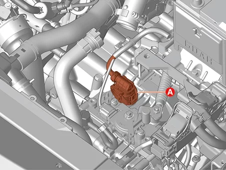
Disconnect the main connector (A).
|
| 4.
|
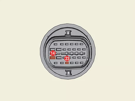
Measure the resistance between power terminal (14) and signal terminal (23).
|
Specification : 5.0 - 5.6 Ω
|
|
28 Brake Control Solenoid Valve (28/B_VFS) Removal
|
•
|
Maintain clean condition so that foreign substance does not get into the
automatic transaxle.
|
|
•
|
Use a coated apron, latex gloves, and stainless tray to prevent foreign
substances from entering
the internal part of the automatic transaxle.
|
|
•
|
Automatic transaxle is composed of delicate components. Be careful not to cause
any damage on the
component when assembling and disassembling.
|
|
| 1.
|
Remove the engine room under cover.
(Refer to Engine Mechanical System - "Engine Room Under
Cover")
|
| 2.
|
Remove the ATF drain plug (A), allow the fluid to drain out and then reinstall the drain plug.
|
Tightening torque :
33.3 - 43.1 N·m (3.4 - 4.4 kgf·m, 24.6 - 31.8 lb·ft)
|
|
•
|
Automatic transaxle fluid (ATF) can be reused. Collect it using
a clean 10 ℓ beaker.
|
|
•
|
The existing ATF drain plug gasket must be replaced with a new
one (do not reuse).
|
|
|
| 3.
|
Disconnect the battery negative ( - ) terminal.
|
| 4.
|
Remove the air cleaner assembly.
(Refer to Engine Mechanical System - "Air Cleaner")
|
| 5.
|
Separate the breather hose clip (A).
|
| 6.
|
Remove the valve body cover (A) upper bolts.
|
Tightening torque :
11.8 - 13.7 N·m (1.2 - 1.4 kgf·m, 8.7 - 10.1 lb·ft)
|
|
| 7.
|
Separate the intercooler hose (A) after removing the clamp.
|
Tightening torque :
4.9 - 6.9 N·m (0.5 - 0.7 kgf·m, 3.6 - 5.1 lb·ft, 43.4 - 60.8 lb·in)
|
|
| 8.
|
Remove the valve body cover (A) after removing the bolts.
|
Tightening torque :
11.8 - 13.7 N·m (1.2 - 1.4 kgf·m, 8.7 - 10.1 lb·ft)
|
|
Be careful not to spill the remaining ATF when removing the valve body cover.
|
|
| 9.
|
Separate the E module (A) after removing the bolts.
|
Tightening torque :
9.8 - 11.8 N·m (1.0 - 1.2 kgf·m, 7.2 - 8.7 lb·ft)
|
|
| 10.
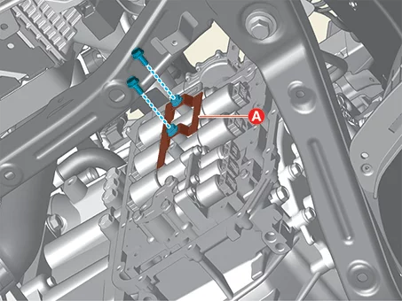
|
Remove the support bracket (A) after removing the bolts.
|
Tightening torque :
9.8 - 11.8 N·m (1.0 - 1.2 kgf·m, 7.2 - 8.7 lb·ft)
|
|
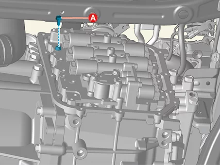
| 11.
|
Remove the valve body bolt (A).
|
Tightening torque :
9.8 - 11.8 N·m (1.0 - 1.2 kgf·m, 7.2 - 8.7 lb·ft)
|
|
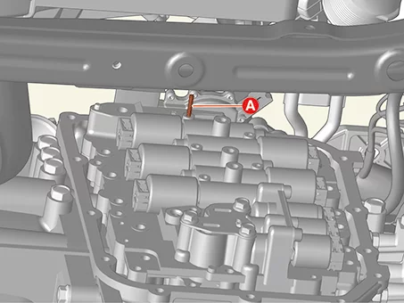
| 12.
|
Remove the roller (A) by using a magnet.
|
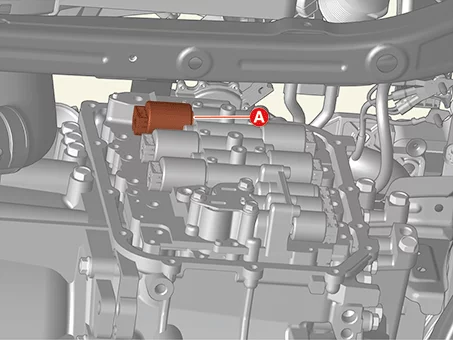
| 13.
|
Remove the 28 brake control solenoid valve (A).
|
28 Brake Control Solenoid Valve (28/B_VFS) Installation
|
•
|
Check the oil pressure characteristics value (A) first before installing the
solenoid valve.
|
|
•
|
If incorrect hydraulic characteristics are entered, shift shock may occur
during TCM learning, so
note the engraved hydraulic values carefully.
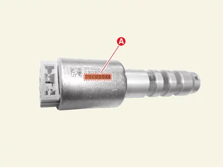
|
|
| 1.
|
Install in reverse order of removal.
|
•
|
Lubricate oil temperature sensor O-ring (A) before installing
the E module.
|
|
•
|
When installing, after mounting the E module, lightly tap the
connector part (A) to
insert the connector certainly and then tighten the bolts.
|
|
•
|
The existing valve body cover gasket (A) must be replaced with
a new one (do not reuse).
|
|
•
|
When installing the valve body cover, tighten the remaining
bolt after pre-tightening the
bolts (A).
|
|
|
| 2.
|
Perform the procedures below after the installation.
| (1)
|
Replenish the automatic transaxle fluid.
(Refer to Hydraulic System - "Fluid")
|
After adding ATF fluid and checking level, clean residual ATF
fluid from outside the
automatic transaxle.
(Wipe off the residual ATF, especially between the automatic
transaxle case and the valve
body cover.)
|
|
| (2)
|
Clear the diagnostic trouble codes (DTC) using the KDS.
Disconnecting the battery negative terminal will not clear the DTCs. Clear DTCs
using the KDS at
all times.
|
| (3)
|
Perform in the order below using the KDS.
(S/W Management → Automatic Transaxle → Resetting Auto T/A Values)
|
Refer to the KDS screen for operating conditions and details.
|
|
| (4)
|
Perform in the order below using the KDS.
(S/W Management → Automatic Transaxle → Oil-pressure Characteristics Input)
|
Refer to the KDS screen for operating conditions and details.
|
|
| (5)
|
Perform the TCM adaptive values learning procedure.
(Refer to Automatic Transaxle Control System -
"Adjustment")
|
| (6)
|
After installing, check for leakage of fluid from hose connection during engine
starting and
running.
|
|
46 Clutch Control Solenoid Valve (46/C_VFS) Specification
Item
|
Specification
|
Control type
|
Direct control, N/L (Normal Low)
|
Control pressure [kPa (kgf/cm², psi)]
|
0 - 1,569.06 (0 - 16, 0 - 227.57)
|
Control current (mA)
|
0 - 1100
|
Coil resistance (Ω)
|
5.0 - 5.6
|
46 Clutch Control Solenoid Valve (46/C_VFS) Components and Components Location
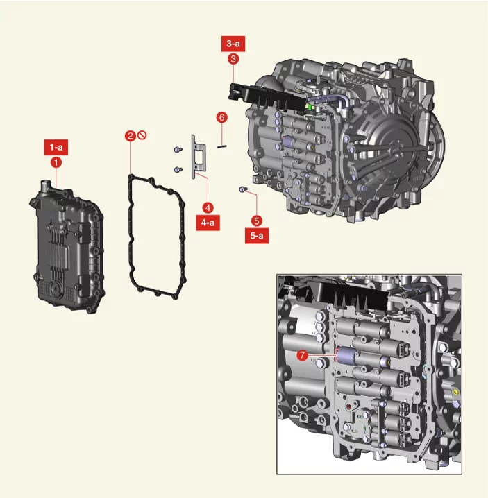
1. Valve Body
Cover
1-a.
11.8 - 13.7 N·m (1.2 - 1.4 kgf·m, 8.7 - 10.1 lb·ft)
2. Valve Body Cover Gasket
3. E
Module
3-a. 9.8 -
11.8 N·m (1.0 - 1.2 kgf·m, 7.2 - 8.7 lb·ft)
|
4. Support Bracket
4-a. 9.8 - 11.8 N·m (1.0
- 1.2
kgf·m, 7.2 - 8.7 lb·ft)
5. Valve Body Bolt
5-a. 9.8 - 11.8 N·m (1.0 - 1.2 kgf·m, 7.2 - 8.7
lb·ft)
6.
Roller
7. 46 Clutch Control Solenoid Valve
|
46 Clutch Control Solenoid Valve (46/C_VFS) Description and Operation
|
•
|
Control the 46 clutch by changing the transmission path of the hydraulic according to the
signal from the
TCM.
|
|
•
|
The solenoid valve is a Variable Force Solenoid (VFS) type.
|
|
•
|
The solenoid valve is a direct control type.
Solenoid Valve Operating Table
Item
|
Solenoid Valve
|
Clutch
|
46/C_VFS
|
46/C
|
P
|
|
|
R
|
|
|
N
|
|
|
1
|
|
|
2
|
|
|
3
|
|
|
4
|
●
|
●
|
5
|
|
|
6
|
●
|
●
|
7
|
|
|
8
|
|
|
Remark
|
● : Connected
|
●: In operation
|
|
46 Clutch Control Solenoid Valve (46/C_VFS) On Vehicle Inspection
| 1.
|
The automatic transaxle system can be more quickly diagnosed for problems by using the vehicle
diagnostic
system (KDS). (Refer to "DTC guide")
| (1)
|
Self diagnosis : Inspect the Diagnostic Trouble Code (DTC) using the KDS
(Refer to DTC guide when fault code is found.)
|
| (2)
|
Data analysis : Check the system input/output values
(Data Analysis → Recorded Data)
|
| (3)
|
Actuation test : Checking the system operation condition
(Data Analysis → System Selection → Actuation Test → 46 Clutch Control Solenoid
Valve)
|
|
| 1.
|
Disconnect the battery negative ( - ) terminal.
|
| 2.
|
Remove the air cleaner assembly.
(Refer to Engine Mechanical System - "Air Cleaner")
|
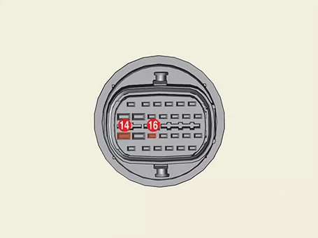
| 3.
|
Disconnect the main connector (A).
|
| 4.
|
Measure the resistance between power terminal (14) and signal terminal (16).
|
Specification : 5.0 - 5.6 Ω
|
|
46 Clutch Control Solenoid Valve (46/C_VFS) Removal
|
•
|
Maintain clean condition so that foreign substance does not get into the
automatic transaxle.
|
|
•
|
Use a coated apron, latex gloves, and stainless tray to prevent foreign
substances from entering
the internal part of the automatic transaxle.
|
|
•
|
Automatic transaxle is composed of delicate components. Be careful not to cause
any damage on the
component when assembling and disassembling.
|
|
| 1.
|
Remove the engine room under cover.
(Refer to Engine Mechanical System - "Engine Room Under
Cover")
|
| 2.
|
Remove the ATF drain plug (A), allow the fluid to drain out and then reinstall the drain plug.
|
Tightening torque :
33.3 - 43.1 N·m (3.4 - 4.4 kgf·m, 24.6 - 31.8 lb·ft)
|
|
•
|
Automatic transaxle fluid (ATF) can be reused. Collect it using
a clean 10 ℓ beaker.
|
|
•
|
The existing ATF drain plug gasket must be replaced with a new
one (do not reuse).
|
|
|
| 3.
|
Disconnect the battery negative ( - ) terminal.
|
| 4.
|
Remove the air cleaner assembly.
(Refer to Engine Mechanical System - "Air Cleaner")
|
| 5.
|
Separate the breather hose clip (A).
|
| 6.
|
Remove the valve body cover (A) upper bolts.
|
Tightening torque :
11.8 - 13.7 N·m (1.2 - 1.4 kgf·m, 8.7 - 10.1 lb·ft)
|
|
| 7.
|
Separate the intercooler hose (A) after removing the clamp.
|
Tightening torque :
4.9 - 6.9 N·m (0.5 - 0.7 kgf·m, 3.6 - 5.1 lb·ft, 43.4 - 60.8 lb·in)
|
|
| 8.
|
Remove the valve body cover (A) after removing the bolts.
|
Tightening torque :
11.8 - 13.7 N·m (1.2 - 1.4 kgf·m, 8.7 - 10.1 lb·ft)
|
|
Be careful not to spill the remaining ATF when removing the valve body cover.
|
|
| 9.
|
Separate the E module (A) after removing the bolts.
|
Tightening torque :
9.8 - 11.8 N·m (1.0 - 1.2 kgf·m, 7.2 - 8.7 lb·ft)
|
|
| 10.
|
Remove the support bracket (A) after removing the bolts.
|
Tightening torque :
9.8 - 11.8 N·m (1.0 - 1.2 kgf·m, 7.2 - 8.7 lb·ft)
|
|
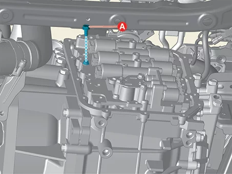
| 11.
|
Remove the valve body bolt (A).
|
Tightening torque :
9.8 - 11.8 N·m (1.0 - 1.2 kgf·m, 7.2 - 8.7 lb·ft)
|
|
| 12.
|
Remove the roller (A) by using a magnet.
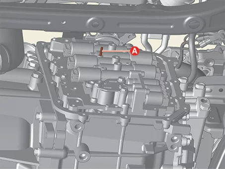
|
| 13.
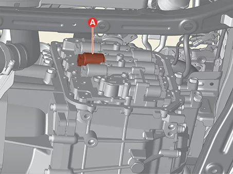
|
Remove the 46 clutch control solenoid valve (A).
|
46 Clutch Control Solenoid Valve (46/C_VFS) Installation
|
•
|
Check the oil pressure characteristics value (A) first before installing the
solenoid valve.
|
|
•
|
If incorrect hydraulic characteristics are entered, shift shock may occur
during TCM learning, so
note the engraved hydraulic values carefully.
|
|
| 1.
|
Install in reverse order of removal.
|
•
|
Lubricate oil temperature sensor O-ring (A) before installing
the E module.
|
|
•
|
When installing, after mounting the E module, lightly tap the
connector part (A) to
insert the connector certainly and then tighten the bolts.
|
|
•
|
The existing valve body cover gasket (A) must be replaced with
a new one (do not reuse).
|
|
•
|
When installing the valve body cover, tighten the remaining
bolt after pre-tightening the
bolts (A).
|
|
|
| 2.
|
Perform the procedures below after the installation.
| (1)
|
Check the ATF level after refilling the automatic transaxle with fluid.
(Refer to Hydraulic System - "Fluid")
|
After adding ATF fluid and checking level, clean residual ATF
fluid from outside the
automatic transaxle.
(Wipe off the residual ATF, especially between the automatic
transaxle case and the valve
body cover.)
|
|
| (2)
|
Clear the diagnostic trouble codes (DTC) using the KDS.
Disconnecting the battery negative terminal will not clear the DTCs. Clear DTCs
using the KDS at
all times.
|
| (3)
|
Perform in the order below using the KDS.
(S/W Management → Automatic Transaxle → Resetting Auto T/A Values)
|
Refer to the KDS screen for operating conditions and details.
|
|
| (4)
|
Perform in the order below using the KDS.
(S/W Management → Automatic Transaxle → Oil-pressure Characteristics Input)
|
Refer to the KDS screen for operating conditions and details.
|
|
| (5)
|
Perform the TCM adaptive values learning procedure.
(Refer to Automatic Transaxle Control System -
"Adjustment")
|
| (6)
|
After installing, check for leakage of fluid from hose connection during engine
starting and
running.
|
|
37R Clutch Control Solenoid Valve (37R/C_VFS) Specification
Item
|
Specification
|
Control type
|
Direct control, N/L (Normal Low)
|
Control pressure [kPa (kgf/cm², psi)]
|
0 - 1,569.06 (0 - 16, 0 - 227.57)
|
Control current (mA)
|
0 - 1100
|
Coil resistance (Ω)
|
5.0 - 5.6
|
37R Clutch Control Solenoid Valve (37R/C_VFS) Components and Components Location
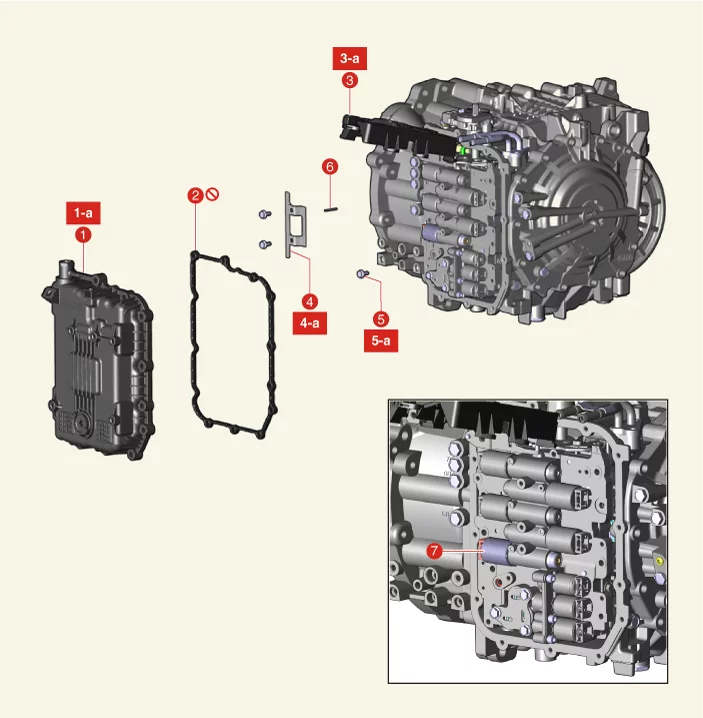
1. Valve Body
Cover
1-a.
11.8 - 13.7 N·m (1.2 - 1.4 kgf·m, 8.7 - 10.1 lb·ft)
2. Valve Body Cover Gasket
3. E
Module
3-a. 9.8 -
11.8 N·m (1.0 - 1.2 kgf·m, 7.2 - 8.7 lb·ft)
|
4. Support Bracket
4-a. 9.8 - 11.8 N·m (1.0
- 1.2
kgf·m, 7.2 - 8.7 lb·ft)
5. Valve Body Bolt
5-a. 9.8 - 11.8 N·m (1.0 - 1.2 kgf·m, 7.2 - 8.7
lb·ft)
6.
Roller
7. 37R Clutch Control Solenoid Valve
|
37R Clutch Control Solenoid Valve (37R/C_VFS) Description and Operation
|
•
|
Control the 37R clutch by changing the transmission path of the hydraulic according to the
signal from
the TCM.
|
|
•
|
The solenoid valve is a Variable Force Solenoid (VFS) type.
|
|
•
|
The solenoid valve is a direct control type.
|
Solenoid Valve Operating Table
Item
|
Solenoid Valve
|
Clutch
|
37R/C_VFS
|
37R/C
|
P
|
|
|
R
|
●
|
●
|
N
|
|
|
1
|
|
|
2
|
|
|
3
|
●
|
●
|
4
|
|
|
5
|
|
|
6
|
|
|
7
|
●
|
●
|
8
|
|
|
Remark
|
● : Connected
|
●: In operation
|
37R Clutch Control Solenoid Valve (37R/C_VFS) On Vehicle Inspection
| 1.
|
The automatic transaxle system can be more quickly diagnosed for problems by using the vehicle
diagnostic
system (KDS). (Refer to "DTC guide")
| (1)
|
Self diagnosis : Inspect the Diagnostic Trouble Code (DTC) using the KDS
(Refer to DTC guide when fault code is found.)
|
| (2)
|
Data analysis : Check the system input/output values
(Data Analysis → Recorded Data)
|
| (3)
|
Actuation test : Checking the system operation condition
(Data Analysis → System Selection → Actuation Test → 37R Clutch Control
Solenoid Valve)
|
|
| 1.
|
Disconnect the battery negative ( - ) terminal.
|
| 2.
|
Remove the air cleaner assembly.
(Refer to Engine Mechanical System - "Air Cleaner")
|
| 3.
|
Disconnect the main connector (A).
|
| 4.
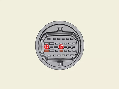
|
Measure the resistance between power terminal (14) and signal terminal (17).
|
Specification : 5.0 - 5.6 Ω
|
|
37R Clutch Control Solenoid Valve (37R/C_VFS) Removal
|
•
|
Maintain clean condition so that foreign substance does not get into the
automatic transaxle.
|
|
•
|
Use a coated apron, latex gloves, and stainless tray to prevent foreign
substances from entering
the internal part of the automatic transaxle.
|
|
•
|
Automatic transaxle is composed of delicate components. Be careful not to cause
any damage on the
component when assembling and disassembling.
|
|
| 1.
|
Remove the engine room under cover.
(Refer to Engine Mechanical System - "Engine Room Under
Cover")
|
| 2.
|
Remove the ATF drain plug (A), allow the fluid to drain out and then reinstall the drain plug.
|
Tightening torque :
33.3 - 43.1 N·m (3.4 - 4.4 kgf·m, 24.6 - 31.8 lb·ft)
|
|
•
|
Automatic transaxle fluid (ATF) can be reused. Collect it using
a clean 10 ℓ beaker.
|
|
•
|
The existing ATF drain plug gasket must be replaced with a new
one (do not reuse).
|
|
|
| 3.
|
Disconnect the battery negative ( - ) terminal.
|
| 4.
|
Remove the air cleaner assembly.
(Refer to Engine Mechanical System - "Air Cleaner")
|
| 5.
|
Separate the breather hose clip (A).
|
| 6.
|
Remove the valve body cover (A) upper bolts.
|
Tightening torque :
11.8 - 13.7 N·m (1.2 - 1.4 kgf·m, 8.7 - 10.1 lb·ft)
|
|
| 7.
|
Separate the intercooler hose (A) after removing the clamp.
|
Tightening torque :
4.9 - 6.9 N·m (0.5 - 0.7 kgf·m, 3.6 - 5.1 lb·ft, 43.4 - 60.8 lb·in)
|
|
| 8.
|
Remove the valve body cover (A) after removing the bolts.
|
Tightening torque :
11.8 - 13.7 N·m (1.2 - 1.4 kgf·m, 8.7 - 10.1 lb·ft)
|
|
Be careful not to spill the remaining ATF when removing the valve body cover.
|
|
| 9.
|
Separate the E module (A) after removing the bolts.
|
Tightening torque :
9.8 - 11.8 N·m (1.0 - 1.2 kgf·m, 7.2 - 8.7 lb·ft)
|
|
| 10.
|
Remove the support bracket (A) after removing the bolts.
|
Tightening torque :
9.8 - 11.8 N·m (1.0 - 1.2 kgf·m, 7.2 - 8.7 lb·ft)
|
|
| 11.
|
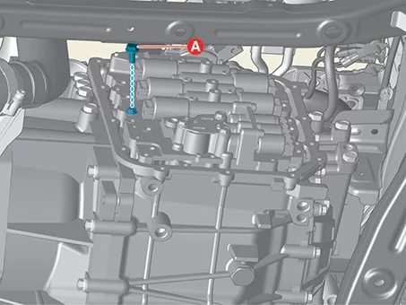
Remove the valve body bolt (A).
|
Tightening torque :
9.8 - 11.8 N·m (1.0 - 1.2 kgf·m, 7.2 - 8.7 lb·ft)
|
|
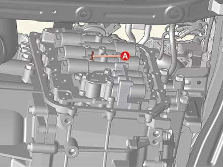
| 12.
|
Remove the roller (A) by using a magnet.
|
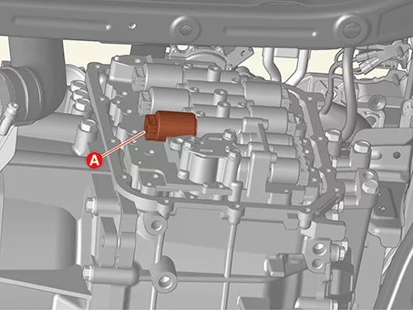
| 13.
|
Remove the 37R clutch control solenoid valve (A).
|
37R Clutch Control Solenoid Valve (37R/C_VFS) Installation
|
•
|
Check the oil pressure characteristics value (A) first before installing the
solenoid valve.
|
|
•
|
If incorrect hydraulic characteristics are entered, shift shock may occur
during TCM learning, so
note the engraved hydraulic values carefully.
|
|
| 1.
|
Install in reverse order of removal.
|
•
|
Lubricate oil temperature sensor O-ring (A) before installing
the E module.
|
|
•
|
When installing, after mounting the E module, lightly tap the
connector part (A) to
insert the connector certainly and then tighten the bolts.
|
|
•
|
The existing valve body cover gasket (A) must be replaced with
a new one (do not reuse).
|
|
•
|
When installing the valve body cover, tighten the remaining
bolt after pre-tightening the
bolts (A).
|
|
|
| 2.
|
Perform the procedures below after the installation.
| (1)
|
Check the ATF level after refilling the automatic transaxle with fluid.
(Refer to Hydraulic System - "Fluid")
|
After adding ATF fluid and checking level, clean residual ATF
fluid from outside the
automatic transaxle.
(Wipe off the residual ATF, especially between the automatic
transaxle case and the valve
body cover.)
|
|
| (2)
|
Clear the diagnostic trouble codes (DTC) using the KDS.
Disconnecting the battery negative terminal will not clear the DTCs. Clear DTCs
using the KDS at
all times.
|
| (3)
|
Perform in the order below using the KDS.
(S/W Management → Automatic Transaxle → Resetting Auto T/A Values)
|
Refer to the KDS screen for operating conditions and details.
|
|
| (4)
|
Perform in the order below using the KDS.
(S/W Management → Automatic Transaxle → Oil-pressure Characteristics Input)
|
Refer to the KDS screen for operating conditions and details.
|
|
| (5)
|
Perform the TCM adaptive values learning procedure.
(Refer to Automatic Transaxle Control System -
"Adjustment")
|
| (6)
|
After installing, check for leakage of fluid from hose connection during engine
starting and
running.
|
|
UD Clutch Control Solenoid Valve (UD/C_VFS) Specification
Item
|
Specification
|
Control type
|
Direct control, N/H (Normal High)
|
Control pressure [kPa (kgf/cm², psi)]
|
0 - 1,569.06 (0 - 16, 0 - 227.57)
|
Control current (mA)
|
0 - 1100
|
Coil resistance (Ω)
|
5.0 - 5.6
|
UD Clutch Control Solenoid Valve (UD/C_VFS) Components and Components Location
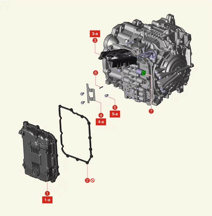
1. Valve Body
Cover
1-a.
11.8 - 13.7 N·m (1.2 - 1.4 kgf·m, 8.7 - 10.1 lb·ft)
2. Valve Body Cover Gasket
3. E
Module
3-a. 9.8 -
11.8 N·m (1.0 - 1.2 kgf·m, 7.2 - 8.7 lb·ft)
|
4. Support Bracket
4-a. 9.8 - 11.8 N·m (1.0
- 1.2
kgf·m, 7.2 - 8.7 lb·ft)
5. Valve Body Bolt
5-a. 9.8 - 11.8 N·m (1.0 - 1.2 kgf·m, 7.2 - 8.7
lb·ft)
6.
Roller
7. UD Clutch Control Solenoid Valve
|
UD Clutch Control Solenoid Valve (UD/C_VFS) Description and Operation
|
•
|
Control the UD clutch by changing the transmission path of the hydraulic according to the
signal from the
TCM.
|
|
•
|
The solenoid valve is a Variable Force Solenoid (VFS) type.
|
|
•
|
The solenoid valve is a direct control type.
Solenoid Valve Operating Table
Item
|
Solenoid Valve
|
Clutch
|
UD/C_VFS
|
UD/C
|
P
|
●
|
|
R
|
●
|
|
N
|
●
|
|
1
|
|
●
|
2
|
|
●
|
3
|
|
●
|
4
|
|
●
|
5
|
|
●
|
6
|
●
|
|
7
|
●
|
|
8
|
●
|
|
Remark
|
● : Connected
|
●: In operation
|
|
UD Clutch Control Solenoid Valve (UD/C_VFS) On Vehicle Inspection
| 1.
|
The automatic transaxle system can be more quickly diagnosed for problems by using the vehicle
diagnostic
system (KDS). (Refer to "DTC guide")
| (1)
|
Self diagnosis : Inspect the Diagnostic Trouble Code (DTC) using the KDS
(Refer to DTC guide when fault code is found.)
|
| (2)
|
Data analysis : Check the system input/output values
(Data Analysis → Recorded Data)
|
| (3)
|
Actuation test : Checking the system operation condition
(Data Analysis → System Selection → Actuation Test → UD Clutch Control Solenoid
Valve)
|
|
| 1.
|
Disconnect the battery negative ( - ) terminal.
|
| 2.
|
Remove the air cleaner assembly.
(Refer to Engine Mechanical System - "Air Cleaner")
|
| 3.
|
Disconnect the main connector (A).
|
| 4.
|
Measure the resistance between power terminal (7) and signal terminal (25).
|
Specification : 5.0 - 5.6 Ω
|
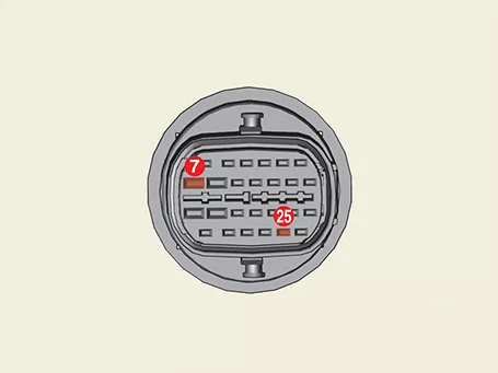
|
UD Clutch Control Solenoid Valve (UD/C_VFS) Removal
|
•
|
Maintain clean condition so that foreign substance does not get into the
automatic transaxle.
|
|
•
|
Use a coated apron, latex gloves, and stainless tray to prevent foreign
substances from entering
the internal part of the automatic transaxle.
|
|
•
|
Automatic transaxle is composed of delicate components. Be careful not to cause
any damage on the
component when assembling and disassembling.
|
|
| 1.
|
Remove the engine room under cover.
(Refer to Engine Mechanical System - "Engine Room Under
Cover")
|
| 2.
|
Remove the ATF drain plug (A), allow the fluid to drain out and then reinstall the drain plug.
|
Tightening torque :
33.3 - 43.1 N·m (3.4 - 4.4 kgf·m, 24.6 - 31.8 lb·ft)
|
|
•
|
Automatic transaxle fluid (ATF) can be reused. Collect it using
a clean 10 ℓ beaker.
|
|
•
|
The existing ATF drain plug gasket must be replaced with a new
one (do not reuse).
|
|
|
| 3.
|
Disconnect the battery negative ( - ) terminal.
|
| 4.
|
Remove the air cleaner assembly.
(Refer to Engine Mechanical System - "Air Cleaner")
|
| 5.
|
Separate the breather hose clip (A).
|
| 6.
|
Remove the valve body cover (A) upper bolts.
|
Tightening torque :
11.8 - 13.7 N·m (1.2 - 1.4 kgf·m, 8.7 - 10.1 lb·ft)
|
|
| 7.
|
Separate the intercooler hose (A) after removing the clamp.
|
Tightening torque :
4.9 - 6.9 N·m (0.5 - 0.7 kgf·m, 3.6 - 5.1 lb·ft, 43.4 - 60.8 lb·in)
|
|
| 8.
|
Remove the valve body cover (A) after removing the bolts.
|
Tightening torque :
11.8 - 13.7 N·m (1.2 - 1.4 kgf·m, 8.7 - 10.1 lb·ft)
|
|
Be careful not to spill the remaining ATF when removing the valve body cover.
|
|
| 9.
|
Separate the E module (A) after removing the bolts.
|
Tightening torque :
9.8 - 11.8 N·m (1.0 - 1.2 kgf·m, 7.2 - 8.7 lb·ft)
|
|
| 10.
|
Remove the support bracket (A) after removing the bolts.
|
Tightening torque :
9.8 - 11.8 N·m (1.0 - 1.2 kgf·m, 7.2 - 8.7 lb·ft)
|
|
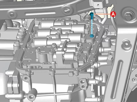
| 11.
|
Remove the valve body bolt (A).
|
Tightening torque :
9.8 - 11.8 N·m (1.0 - 1.2 kgf·m, 7.2 - 8.7 lb·ft)
|
|
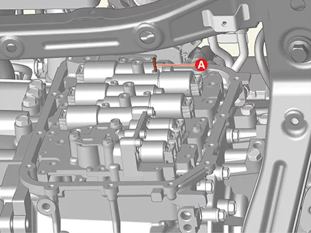
| 12.
|
Remove the roller (A) by using a magnet.
|
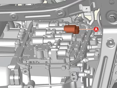
| 13.
|
Remove the UD clutch control solenoid valve (A).
|
UD Clutch Control Solenoid Valve (UD/C_VFS) Installation
|
•
|
Check the oil pressure characteristics value (A) first before installing the
solenoid valve.
|
|
•
|
If incorrect hydraulic characteristics are entered, shift shock may occur
during TCM learning, so
note the engraved hydraulic values carefully.
|
|
| 1.
|
Install in reverse order of removal.
|
•
|
Lubricate oil temperature sensor O-ring (A) before installing
the E module.
|
|
•
|
When installing, after mounting the E module, lightly tap the
connector part (A) to
insert the connector certainly and then tighten the bolts.
|
|
•
|
The existing valve body cover gasket (A) must be replaced with
a new one (do not reuse).
|
|
•
|
When installing the valve body cover, tighten the remaining
bolt after pre-tightening the
bolts (A).
|
|
|
| 2.
|
Perform the procedures below after the installation.
| (1)
|
Check the ATF level after refilling the automatic transaxle with fluid.
(Refer to Hydraulic System - "Fluid")
|
After adding ATF fluid and checking level, clean residual ATF
fluid from outside the
automatic transaxle.
(Wipe off the residual ATF, especially between the automatic
transaxle case and the valve
body cover.)
|
|
| (2)
|
Clear the diagnostic trouble codes (DTC) using the KDS.
Disconnecting the battery negative terminal will not clear the DTCs. Clear DTCs
using the KDS at
all times.
|
| (3)
|
Perform in the order below using the KDS.
(S/W Management → Automatic Transaxle → Resetting Auto T/A Values)
|
Refer to the KDS screen for operating conditions and details.
|
|
| (4)
|
Perform in the order below using the KDS.
(S/W Management → Automatic Transaxle → Oil-pressure Characteristics Input)
|
Refer to the KDS screen for operating conditions and details.
|
|
| (5)
|
Perform the TCM adaptive values learning procedure.
(Refer to Automatic Transaxle Control System -
"Adjustment")
|
| (6)
|
After installing, check for leakage of fluid from hose connection during engine
starting and
running.
|
|
OD Clutch & LR Brake Control Solenoid Valve (OD/C & LR/B_VFS) Specification
Item
|
Specification
|
Control type
|
Direct control, N/H (Normal High)
|
Control pressure [kPa (kgf/cm², psi)]
|
0 - 1,569.06 (0 - 16, 0 - 227.57)
|
Control current (mA)
|
0 - 1100
|
Coil resistance (Ω)
|
5.0 - 5.6
|
OD Clutch & LR Brake Control Solenoid Valve (OD/C & LR/B_VFS) Components and Components Location
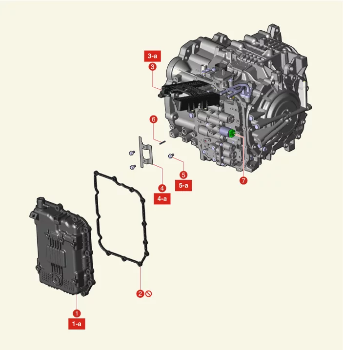
1. Valve Body Cover
1-a. 11.8 - 13.7 N·m
(1.2 - 1.4
kgf·m, 8.7 - 10.1 lb·ft)
2. Valve Body Cover Gasket
3. E Module
3-a. 9.8 - 11.8 N·m (1.0 -
1.2 kgf·m,
7.2 - 8.7 lb·ft)
|
4. Support Bracket
4-a. 9.8 - 11.8 N·m (1.0
- 1.2
kgf·m, 7.2 - 8.7 lb·ft)
5. Valve Body Bolt
5-a. 9.8 - 11.8 N·m (1.0 - 1.2 kgf·m, 7.2 - 8.7
lb·ft)
6.
Roller
7. OD Clutch & LR Brake Control Solenoid Valve
|
OD Clutch & LR Brake Control Solenoid Valve (OD/C & LR/B_VFS) Description and Operation
|
•
|
Control the OD clutch and LR brake by changing the transmission path of the hydraulic according
to the
signal from the TCM.
|
|
•
|
The solenoid valve is a Variable Force Solenoid (VFS) type.
|
|
•
|
The solenoid valve is a direct control type.
|
Solenoid Valve Operating Table
Item
|
Solenoid Valve
|
Clutch
|
Brake
|
OD/C & LR/B_VFS
|
OD/C
|
LR/B
|
P
|
|
|
●
|
R
|
|
|
●
|
N
|
|
|
●
|
1
|
|
|
●
|
2
|
●
|
|
|
3
|
●
|
|
|
4
|
●
|
|
|
5
|
|
●
|
|
6
|
|
●
|
|
7
|
|
●
|
|
8
|
|
●
|
|
Remark
|
● : Connected
|
●: In operation
|
OD Clutch & LR Brake Control Solenoid Valve (OD/C & LR/B_VFS) On Vehicle Inspection
| 1.
|
The automatic transaxle system can be more quickly diagnosed for problems by using the vehicle
diagnostic
system (KDS). (Refer to "DTC guide")
| (1)
|
Self diagnosis : Inspect the Diagnostic Trouble Code (DTC) using the KDS
(Refer to DTC guide when fault code is found.)
|
| (2)
|
Data analysis : Check the system input/output values
(Data Analysis → Recorded Data)
|
| (3)
|
Actuation test : Checking the system operation condition
(Data Analysis → System Selection → Actuation Test → OD clutch & LR Brake
Control Solenoid
Valve)
|
|
| 1.
|
Disconnect the battery negative ( - ) terminal.
|
| 2.
|
Remove the air cleaner assembly.
(Refer to Engine Mechanical System - "Air Cleaner")
|
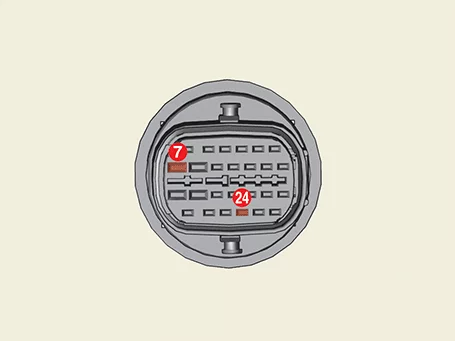
| 3.
|
Disconnect the main connector (A).
|
| 4.
|
Measure the resistance between power terminal (7) and signal terminal (24).
|
Specification : 5.0 - 5.6 Ω
|
|
OD Clutch & LR Brake Control Solenoid Valve (OD/C & LR/B_VFS) Removal
|
•
|
Maintain clean condition so that foreign substance does not get into the
automatic transaxle.
|
|
•
|
Use a coated apron, latex gloves, and stainless tray to prevent foreign
substances from entering
the internal part of the automatic transaxle.
|
|
•
|
Automatic transaxle is composed of delicate components. Be careful not to cause
any damage on the
component when assembling and disassembling.
|
|
| 1.
|
Remove the engine room under cover.
(Refer to Engine Mechanical System - "Engine Room Under
Cover")
|
| 2.
|
Remove the ATF drain plug (A), allow the fluid to drain out and then reinstall the drain plug.
|
Tightening torque :
33.3 - 43.1 N·m (3.4 - 4.4 kgf·m, 24.6 - 31.8 lb·ft)
|
|
•
|
Automatic transaxle fluid (ATF) can be reused. Collect it using
a clean 10 ℓ beaker.
|
|
•
|
The existing ATF drain plug gasket must be replaced with a new
one (do not reuse).
|
|
|
| 3.
|
Disconnect the battery negative ( - ) terminal.
|
| 4.
|
Remove the air cleaner assembly.
(Refer to Engine Mechanical System - "Air Cleaner")
|
| 5.
|
Separate the breather hose clip (A).
|
| 6.
|
Remove the valve body cover (A) upper bolts.
|
Tightening torque :
11.8 - 13.7 N·m (1.2 - 1.4 kgf·m, 8.7 - 10.1 lb·ft)
|
|
| 7.
|
Separate the intercooler hose (A) after removing the clamp.
|
Tightening torque :
4.9 - 6.9 N·m (0.5 - 0.7 kgf·m, 3.6 - 5.1 lb·ft, 43.4 - 60.8 lb·in)
|
|
| 8.
|
Remove the valve body cover (A) after removing the bolts.
|
Tightening torque :
11.8 - 13.7 N·m (1.2 - 1.4 kgf·m, 8.7 - 10.1 lb·ft)
|
|
Be careful not to spill the remaining ATF when removing the valve body cover.
|
|
| 9.
|
Separate the E module (A) after removing the bolts.
|
Tightening torque :
9.8 - 11.8 N·m (1.0 - 1.2 kgf·m, 7.2 - 8.7 lb·ft)
|
|
| 10.
|
Remove the support bracket (A) after removing the bolts.
|
Tightening torque :
9.8 - 11.8 N·m (1.0 - 1.2 kgf·m, 7.2 - 8.7 lb·ft)
|
|
| 11.
|
Remove the roller (A) by using a magnet.
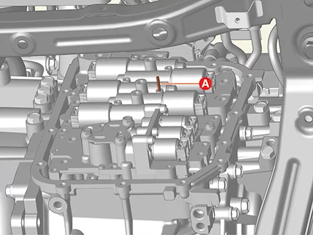
|
| 12.
|
Remove the OD clutch & LR brake control solenoid valve (A).
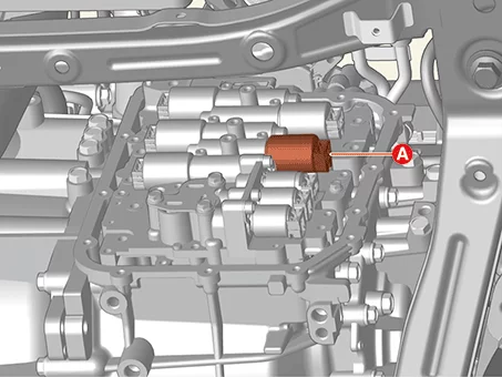
|
OD Clutch & LR Brake Control Solenoid Valve (OD/C & LR/B_VFS) Installation
|
•
|
Check the oil pressure characteristics value (A) first before installing the
solenoid valve.
|
|
•
|
If incorrect hydraulic characteristics are entered, shift shock may occur
during TCM learning, so
note the engraved hydraulic values carefully.
|
|
| 1.
|
Install in reverse order of removal.
|
•
|
Lubricate oil temperature sensor O-ring (A) before installing
the E module.
|
|
•
|
When installing, after mounting the E module, lightly tap the
connector part (A) to
insert the connector certainly and then tighten the bolts.
|
|
•
|
The existing valve body cover gasket (A) must be replaced with
a new one (do not reuse).
|
|
•
|
When installing the valve body cover, tighten the remaining
bolt after pre-tightening the
bolts (A).
|
|
|
| 2.
|
Perform the procedures below after the installation.
| (1)
|
Check the ATF level after refilling the automatic transaxle with fluid.
(Refer to Hydraulic System - "Fluid")
|
After adding ATF fluid and checking level, clean residual ATF
fluid from outside the
automatic transaxle.
(Wipe off the residual ATF, especially between the automatic
transaxle case and the valve
body cover.)
|
|
| (2)
|
Clear the diagnostic trouble codes (DTC) using the KDS.
Disconnecting the battery negative terminal will not clear the DTCs. Clear DTCs
using the KDS at
all times.
|
| (3)
|
Perform in the order below using the KDS.
(S/W Management → Automatic Transaxle → Resetting Auto T/A Values)
|
Refer to the KDS screen for operating conditions and details.
|
|
| (4)
|
Perform in the order below using the KDS.
(S/W Management → Automatic Transaxle → Oil-pressure Characteristics Input)
|
Refer to the KDS screen for operating conditions and details.
|
|
| (5)
|
Perform the TCM adaptive values learning procedure.
(Refer to Automatic Transaxle Control System -
"Adjustment")
|
| (6)
|
After installing, check for leakage of fluid from hose connection during engine
starting and
running.
|
|
SS-A Solenoid Valve (SS-A_ON/OFF) Specification
Item
|
Specification
|
Control type
|
ON / OFF
|
Control pressure [kPa (kgf/cm², psi)]
|
0 - 490.33 (0 - 5.0, 0 - 71.12)
|
Control voltage (V)
|
9 - 16
|
Coil resistance (Ω)
|
10 - 11
|
SS-A Solenoid Valve (SS-A_ON/OFF) Components and Components Location
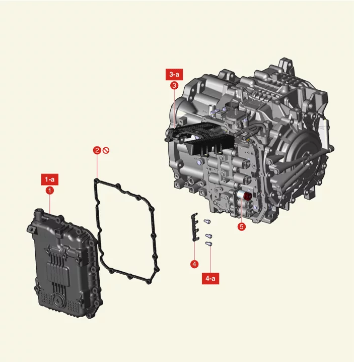
1. Valve Body
Cover
1-a.
11.8 - 13.7 N·m (1.2 - 1.4 kgf·m, 8.7 - 10.1 lb·ft)
2. Valve Body Cover Gasket
3. E
Module
3-a. 9.8 -
11.8 N·m (1.0 - 1.2 kgf·m, 7.2 - 8.7 lb·ft)
|
4. Support Bracket
4-a. 9.8 - 11.8 N·m (1.0
- 1.2
kgf·m, 7.2 - 8.7 lb·ft)
5. SS-A Solenoid Valve
|
SS-A Solenoid Valve (SS-A_ON/OFF) Description and Operation
|
•
|
SS-A solenoid valve is ON/OFF type.
|
|
•
|
When TCM supplies variable current to solenoid valve, the solenoid valve operates and controls
the speed
range.
|
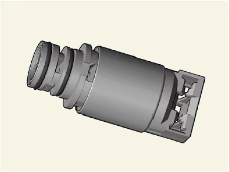
Solenoid Valve Operating Table
Item
|
Solenoid Valve
|
SS-A
|
P
|
●
|
R
|
●
|
N
|
●
|
1
|
●
|
2
|
|
3
|
|
4
|
|
5
|
|
6
|
|
7
|
|
8
|
|
Remark
|
● : Connected
|
SS-A Solenoid Valve (SS-A_ON/OFF) On Vehicle Inspection
| 1.
|
The automatic transaxle system can be more quickly diagnosed for problems by using the vehicle
diagnostic
system (KDS). (Refer to "DTC guide")
| (1)
|
Self diagnosis : Inspect the Diagnostic Trouble Code (DTC) using the KDS
(Refer to DTC guide when fault code is found.)
|
| (2)
|
Data analysis : Check the system input/output values
(Data Analysis → Recorded Data)
|
| (3)
|
Actuation test : Checking the system operation condition
(Data Analysis → System Selection → Actuation Test → SS-A Solenoid Valve)
|
|
| 1.
|
Disconnect the battery negative ( - ) terminal.
|
| 2.
|
Remove the air cleaner assembly.
(Refer to Engine Mechanical System - "Air Cleaner")
|
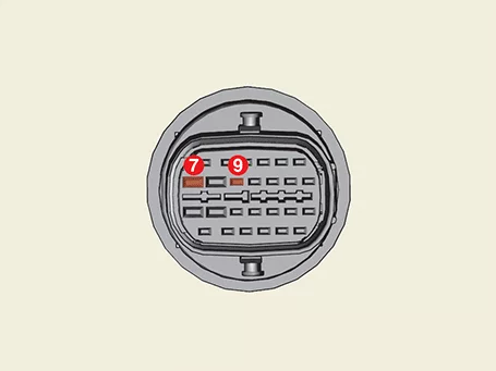
| 3.
|
Disconnect the main connector (A).
|
| 4.
|
Measure the resistance between power terminal (7) and signal terminal (9).
|
Specification : 10 - 11 Ω
|
|
SS-A Solenoid Valve (SS-A_ON/OFF) Removal
|
•
|
Maintain clean condition so that foreign substance does not get into the
automatic transaxle.
|
|
•
|
Use a coated apron, latex gloves, and stainless tray to prevent foreign
substances from entering
the internal part of the automatic transaxle.
|
|
•
|
Automatic transaxle is composed of delicate components. Be careful not to cause
any damage on the
component when assembling and disassembling.
|
|
| 1.
|
Remove the engine room under cover.
(Refer to Engine Mechanical System - "Engine Room Under
Cover")
|
| 2.
|
Remove the ATF drain plug (A), allow the fluid to drain out and then reinstall the drain plug.
|
Tightening torque :
33.3 - 43.1 N·m (3.4 - 4.4 kgf·m, 24.6 - 31.8 lb·ft)
|
|
•
|
Automatic transaxle fluid (ATF) can be reused. Collect it using
a clean 10 ℓ beaker.
|
|
•
|
The existing ATF drain plug gasket must be replaced with a new
one (do not reuse).
|
|
|
| 3.
|
Disconnect the battery negative ( - ) terminal.
|
| 4.
|
Remove the air cleaner assembly.
(Refer to Engine Mechanical System - "Air Cleaner")
|
| 5.
|
Separate the breather hose clip (A).
|
| 6.
|
Remove the valve body cover (A) upper bolts.
|
Tightening torque :
11.8 - 13.7 N·m (1.2 - 1.4 kgf·m, 8.7 - 10.1 lb·ft)
|
|
| 7.
|
Separate the intercooler hose (A) after removing the clamp.
|
Tightening torque :
4.9 - 6.9 N·m (0.5 - 0.7 kgf·m, 3.6 - 5.1 lb·ft, 43.4 - 60.8 lb·in)
|
|
| 8.
|
Remove the valve body cover (A) after removing the bolts.
|
Tightening torque :
11.8 - 13.7 N·m (1.2 - 1.4 kgf·m, 8.7 - 10.1 lb·ft)
|
|
Be careful not to spill the remaining ATF when removing the valve body cover.
|
|
| 9.
|
Separate the E module (A) after removing the bolts.
|
Tightening torque :
9.8 - 11.8 N·m (1.0 - 1.2 kgf·m, 7.2 - 8.7 lb·ft)
|
|
| 10.
|
Remove the support bracket (A) after removing the bolts.
|
Tightening torque :
9.8 - 11.8 N·m (1.0 - 1.2 kgf·m, 7.2 - 8.7 lb·ft)
|
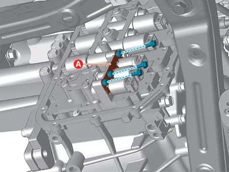
|
| 11.
|
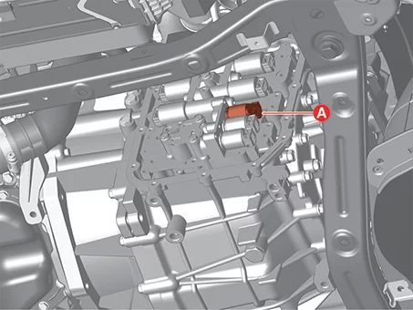
Remove the SS-A solenoid valve (A).
|
SS-A Solenoid Valve (SS-A_ON/OFF) Installation
| 1.
|
Install in reverse order of removal.
|
•
|
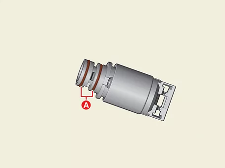
When installing, apply the ATF oil or petroleum jelly to the
O-rings (A) to prevent
damage.
|
|
•
|
Lubricate oil temperature sensor O-ring (A) before installing
the E module.
|
|
•
|
When installing, after mounting the E module, lightly tap the
connector part (A) to
insert the connector certainly and then tighten the bolts.
|
|
•
|
The existing valve body cover gasket (A) must be replaced with
a new one (do not reuse).
|
|
•
|
When installing the valve body cover, tighten the remaining
bolt after pre-tightening the
bolts (A).
|
|
|
| 2.
|
Perform the procedures below after the installation.
| (1)
|
Check the ATF level after refilling the automatic transaxle with fluid.
(Refer to Hydraulic System - "Fluid")
|
After adding ATF fluid and checking level, clean residual ATF
fluid from outside the
automatic transaxle.
(Wipe off the residual ATF, especially between the automatic
transaxle case and the valve
body cover.)
|
|
| (2)
|
Clear the diagnostic trouble codes (DTC) using the KDS.
(Disconnecting the battery negative terminal will not clear the DTCs. Clear
DTCs using the KDS at
all times.)
|
| (3)
|
After installing, check for leakage of fluid from hose connection during engine
starting and
running.
|
|
Torque Converter Control Solenoid Valve (T/CON_VFS) Specification
Item
|
Specification
|
Control type
|
Indirect control, N/L (Normal Low)
|
Control pressure [kPa (kgf/cm², psi)]
|
0 - 519.75 (0 - 5.3, 0 - 75.38)
|
Control current (mA)
|
0 - 850
|
Coil resistance (Ω)
|
4.8 - 5.4
|
Torque Converter Control Solenoid Valve (T/CON_VFS) Components and Components Location
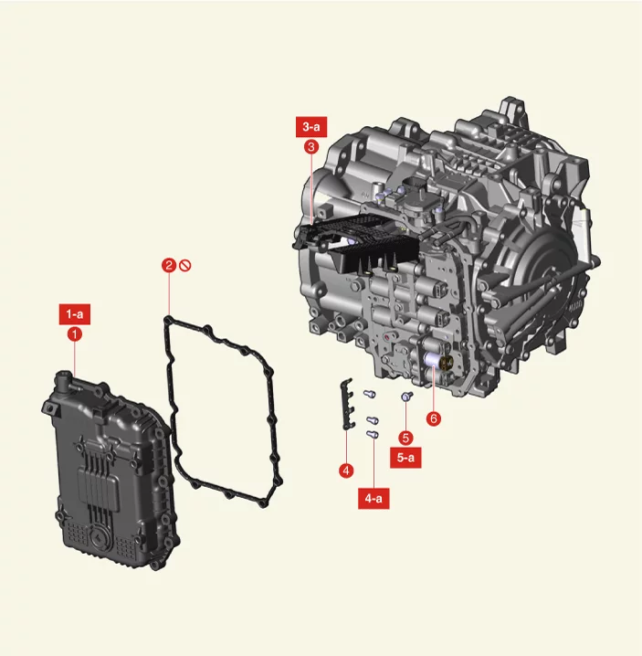
1. Valve Body
Cover
1-a.
11.8 - 13.7 N·m (1.2 - 1.4 kgf·m, 8.7 - 10.1 lb·ft)
2. Valve Body Cover Gasket
3. E
Module
3-a. 9.8 -
11.8 N·m (1.0 - 1.2 kgf·m, 7.2 - 8.7 lb·ft)
|
4. Support Bracket
4-a. 9.8 - 11.8 N·m (1.0
- 1.2
kgf·m, 7.2 - 8.7 lb·ft)
5. Valve Body Bolt
5-a. 9.8 - 11.8 N·m (1.0 - 1.2 kgf·m, 7.2 - 8.7
lb·ft)
6.
Torque Converter Control Solenoid Valve
|
Torque Converter Control Solenoid Valve (T/CON_VFS) Description and Operation
|
•
|
Control the damper clutch by changing the transmission path of the hydraulic according to the
signal from
the TCM.
|
|
•
|
The solenoid valve is a Variable Force Solenoid (VFS) type.
|
|
•
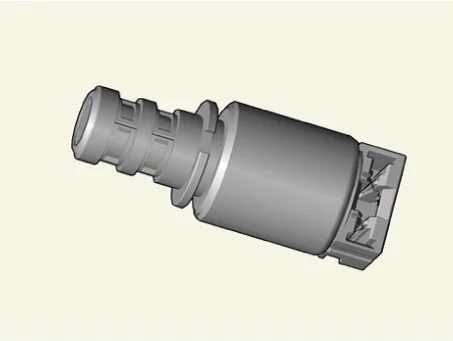
|
This solenoid valve is indirect control type.
|
Solenoid Valve Operating Table
Item
|
Solenoid Valve
|
T/CON_VFS
|
P
|
|
R
|
|
N
|
|
1
|
◎
|
2
|
◎
|
3
|
◎
|
4
|
◎
|
5
|
◎
|
6
|
◎
|
7
|
◎
|
8
|
◎
|
Remark
|
◎ : Variable connected
|
Torque Converter Control Solenoid Valve (T/CON_VFS) On Vehicle Inspection
| 1.
|
The automatic transaxle system can be more quickly diagnosed for problems by using the vehicle
diagnostic
system (KDS). (Refer to "DTC guide")
| (1)
|
Self diagnosis : Inspect the Diagnostic Trouble Code (DTC) using the KDS
(Refer to DTC guide when fault code is found.)
|
| (2)
|
Data analysis : Check the system input/output values
(Data Analysis → Recorded Data)
|
| (3)
|
Actuation test : Checking the system operation condition
(Data Analysis → System Selection → Actuation Test → Torque Converter Control
Solenoid Valve)
|
|
| 2.
|
Disconnect the battery negative ( - ) terminal.
|
| 3.
|
Remove the air cleaner assembly.
(Refer to Engine Mechanical System - "Air Cleaner")
|
| 4.
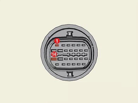
|
Disconnect the main connector (A).
|
| 5.
|
Measure the resistance between power terminal (14) and signal terminal (1).
|
Specification : 4.8 - 5.4 Ω
|
|
Torque Converter Control Solenoid Valve (T/CON_VFS) Removal
|
•
|
Maintain clean condition so that foreign substance does not get into the
automatic transaxle.
|
|
•
|
Use a coated apron, latex gloves, and stainless tray to prevent foreign
substances from entering
the internal part of the automatic transaxle.
|
|
•
|
Automatic transaxle is composed of delicate components. Be careful not to cause
any damage on the
component when assembling and disassembling.
|
|
| 1.
|
Remove the engine room under cover.
(Refer to Engine Mechanical System - "Engine Room Under
Cover")
|
| 2.
|
Remove the ATF drain plug (A), allow the fluid to drain out and then reinstall the drain plug.
|
Tightening torque :
33.3 - 43.1 N·m (3.4 - 4.4 kgf·m, 24.6 - 31.8 lb·ft)
|
|
•
|
Automatic transaxle fluid (ATF) can be reused. Collect it using
a clean 10 ℓ beaker.
|
|
•
|
The existing ATF drain plug gasket must be replaced with a new
one (do not reuse).
|
|
|
| 3.
|
Disconnect the battery negative ( - ) terminal.
|
| 4.
|
Remove the air cleaner assembly.
(Refer to Engine Mechanical System - "Air Cleaner")
|
| 5.
|
Separate the breather hose clip (A).
|
| 6.
|
Remove the valve body cover (A) upper bolts.
|
Tightening torque :
11.8 - 13.7 N·m (1.2 - 1.4 kgf·m, 8.7 - 10.1 lb·ft)
|
|
| 7.
|
Separate the intercooler hose (A) after removing the clamp.
|
Tightening torque :
4.9 - 6.9 N·m (0.5 - 0.7 kgf·m, 3.6 - 5.1 lb·ft, 43.4 - 60.8 lb·in)
|
|
| 8.
|
Remove the valve body cover (A) after removing the bolts.
|
Tightening torque :
11.8 - 13.7 N·m (1.2 - 1.4 kgf·m, 8.7 - 10.1 lb·ft)
|
|
Be careful not to spill the remaining ATF when removing the valve body cover.
|
|
| 9.
|
Separate the E module (A) after removing the bolts.
|
Tightening torque :
9.8 - 11.8 N·m (1.0 - 1.2 kgf·m, 7.2 - 8.7 lb·ft)
|
|
| 10.
|
Remove the support bracket (A) after removing the bolts.
|
Tightening torque :
9.8 - 11.8 N·m (1.0 - 1.2 kgf·m, 7.2 - 8.7 lb·ft)
|
|
| 11.
|
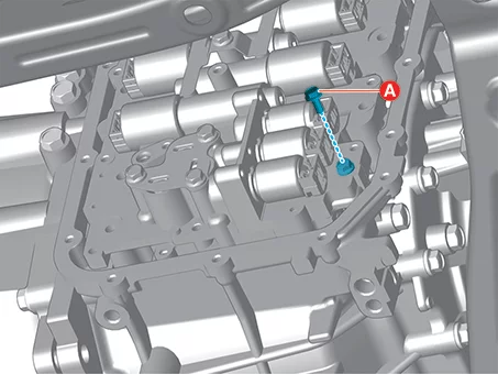
Remove the valve body bolt (A).
|
Tightening torque :
9.8 - 11.8 N·m (1.0 - 1.2 kgf·m, 7.2 - 8.7 lb·ft)
|
|
| 12.
|
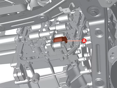
Remove the torque converter control solenoid valve (A).
|
Torque Converter Control Solenoid Valve (T/CON_VFS) Installation
| 1.
|
Install in reverse order of removal.
|
•
|
Lubricate oil temperature sensor O-ring (A) before installing
the E module.
|
|
•
|
When installing, after mounting the E module, lightly tap the
connector part (A) to
insert the connector certainly and then tighten the bolts.
|
|
•
|
The existing valve body cover gasket (A) must be replaced with
a new one (do not reuse).
|
|
•
|
When installing the valve body cover, tighten the remaining
bolt after pre-tightening the
bolts (A).
|
|
|
| 2.
|
Perform the procedures below after the installation.
| (1)
|
Check the ATF level after refilling the automatic transaxle with fluid.
(Refer to Hydraulic System - "Fluid")
|
After adding ATF fluid and checking level, clean residual ATF
fluid from outside the
automatic transaxle.
(Wipe off the residual ATF, especially between the automatic
transaxle case and the valve
body cover.)
|
|
| (2)
|
Clear the diagnostic trouble codes (DTC) using the KDS.
Disconnecting the battery negative terminal will not clear the DTCs. Clear DTCs
using the KDS at
all times.
|
| (3)
|
Perform in the order below using the KDS.
(S/W Management → Automatic Transaxle → Resetting Auto T/A Values)
|
Refer to the KDS screen for operating conditions and details.
|
|
| (4)
|
Perform the TCM adaptive values learning procedure.
(Refer to Automatic Transaxle Control System -
"Adjustment")
|
| (5)
|
After installing, check for leakage of fluid from hose connection during engine
starting and
running.
|
|
Line Pressure Control Solenoid Valve (LINE_VFS) Specification
Item
|
Specification
|
Control type
|
Indirect control, N/H (Normal High)
|
Control pressure [kPa (kgf/cm², psi)]
|
0 - 519.75 (0 - 5.3, 0 - 75.38)
|
Control current (mA)
|
0 - 850
|
Coil resistance (Ω)
|
4.8 - 5.4
|
Line Pressure Control Solenoid Valve (LINE_VFS) Components and Components Location
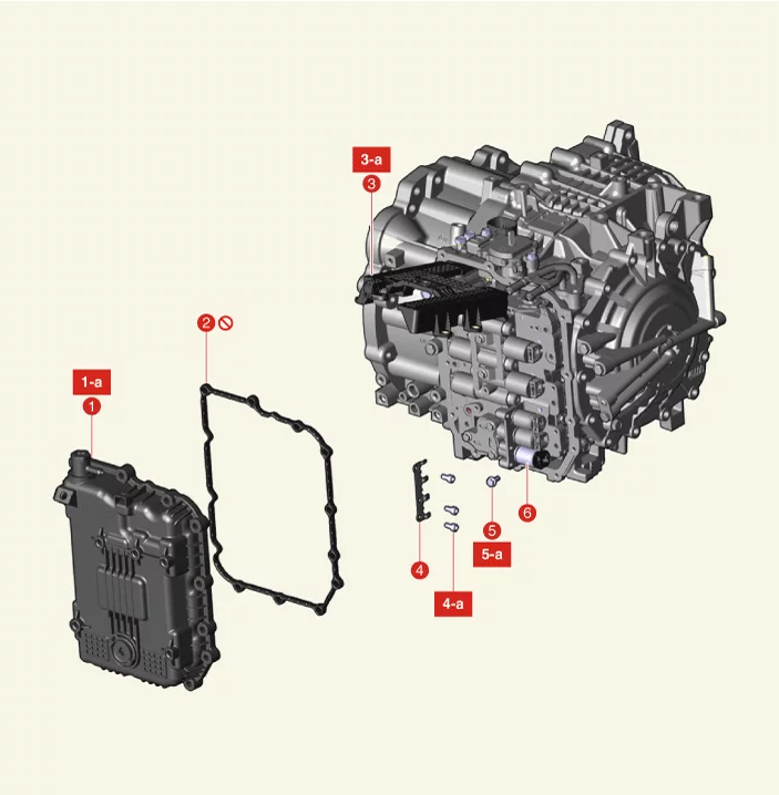
1. Valve Body
Cover
1-a.
11.8 - 13.7 N·m (1.2 - 1.4 kgf·m, 8.7 - 10.1 lb·ft)
2. Valve Body Cover Gasket
3. E
Module
3-a. 9.8 -
11.8 N·m (1.0 - 1.2 kgf·m, 7.2 - 8.7 lb·ft)
|
4. Support Bracket
4-a. 9.8 - 11.8 N·m (1.0
- 1.2
kgf·m, 7.2 - 8.7 lb·ft)
5. Valve Body Bolt
5-a. 9.8 - 11.8 N·m (1.0 - 1.2 kgf·m, 7.2 - 8.7
lb·ft)
6.
Line Pressure Control Solenoid Valve
|
Line Pressure Control Solenoid Valve (LINE_VFS) Description and Operation
|
•
|
Line pressure solenoid valve is a Variable Force Solenoid (VFS) type.
|
|
•
|
When TCM supplies variable current to solenoid valve, hydraulic pressure is controlled
indirectly by
solenoid valve.
|
Solenoid Valve Operating Table
Item
|
Solenoid Valve
|
LINE_VFS
|
P
|
◎
|
R
|
◎
|
N
|
◎
|
1
|
◎
|
2
|
◎
|
3
|
◎
|
4
|
◎
|
5
|
◎
|
6
|
◎
|
7
|
◎
|
8
|
◎
|
Remark
|
◎ : Variable connected
|
Line Pressure Control Solenoid Valve (LINE_VFS) On Vehicle Inspection
| 1.
|
The automatic transaxle system can be more quickly diagnosed for problems by using the vehicle
diagnostic
system (KDS). (Refer to "DTC guide")
| (1)
|
Self diagnosis : Inspect the Diagnostic Trouble Code (DTC) using the KDS
(Refer to DTC guide when fault code is found.)
|
| (2)
|
Data analysis : Check the system input/output values
(Data Analysis → Recorded Data)
|
| (3)
|
Actuation test : Checking the system operation condition
(Data Analysis → System Selection → Actuation Test → Line Pressure Control
Solenoid Valve)
|
|
| 1.
|
Disconnect the battery negative ( - ) terminal.
|
| 2.
|
Remove the air cleaner assembly.
(Refer to Engine Mechanical System - "Air Cleaner")
|
| 3.
|
Disconnect the main connector (A).
|
| 4.
|
Measure the resistance between power terminal (7) and signal terminal (22).
|
Specification : 4.8 - 5.4 Ω
|
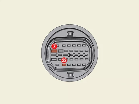
|
Line Pressure Control Solenoid Valve (LINE_VFS) Removal
|
•
|
Maintain clean condition so that foreign substance does not get into the
automatic transaxle.
|
|
•
|
Use a coated apron, latex gloves, and stainless tray to prevent foreign
substances from entering
the internal part of the automatic transaxle.
|
|
•
|
Automatic transaxle is composed of delicate components. Be careful not to cause
any damage on the
component when assembling and disassembling.
|
|
| 1.
|
Remove the engine room under cover.
(Refer to Engine Mechanical System - "Engine Room Under
Cover")
|
| 2.
|
Remove the ATF drain plug (A), allow the fluid to drain out and then reinstall the drain plug.
|
Tightening torque :
33.3 - 43.1 N·m (3.4 - 4.4 kgf·m, 24.6 - 31.8 lb·ft)
|
|
•
|
Automatic transaxle fluid (ATF) can be reused. Collect it using
a clean 10 ℓ beaker.
|
|
•
|
The existing ATF drain plug gasket must be replaced with a new
one (do not reuse).
|
|
|
| 3.
|
Disconnect the battery negative ( - ) terminal.
|
| 4.
|
Remove the air cleaner assembly.
(Refer to Engine Mechanical System - "Air Cleaner")
|
| 5.
|
Separate the breather hose clip (A).
|
| 6.
|
Remove the valve body cover (A) upper bolts.
|
Tightening torque :
11.8 - 13.7 N·m (1.2 - 1.4 kgf·m, 8.7 - 10.1 lb·ft)
|
|
| 7.
|
Separate the intercooler hose (A) after removing the clamp.
|
Tightening torque :
4.9 - 6.9 N·m (0.5 - 0.7 kgf·m, 3.6 - 5.1 lb·ft, 43.4 - 60.8 lb·in)
|
|
| 8.
|
Remove the valve body cover (A) after removing the bolts.
|
Tightening torque :
11.8 - 13.7 N·m (1.2 - 1.4 kgf·m, 8.7 - 10.1 lb·ft)
|
|
Be careful not to spill the remaining ATF when removing the valve body cover.
|
|
| 9.
|
Separate the E module (A) after removing the bolts.
|
Tightening torque :
9.8 - 11.8 N·m (1.0 - 1.2 kgf·m, 7.2 - 8.7 lb·ft)
|
|
| 10.
|
Remove the support bracket (A) after removing the bolts.
|
Tightening torque :
9.8 - 11.8 N·m (1.0 - 1.2 kgf·m, 7.2 - 8.7 lb·ft)
|
|
| 11.
|
Remove the valve body bolt (A).
|
Tightening torque :
9.8 - 11.8 N·m (1.0 - 1.2 kgf·m, 7.2 - 8.7 lb·ft)
|
|
| 12.
|
Remove the line pressure control solenoid valve (A).
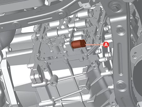
|
Line Pressure Control Solenoid Valve (LINE_VFS) Installation
| 1.
|
Install in reverse order of removal.
|
•
|
Lubricate oil temperature sensor O-ring (A) before installing
the E module.
|
|
•
|
When installing, after mounting the E module, lightly tap the
connector part (A) to
insert the connector certainly and then tighten the bolts.
|
|
•
|
The existing valve body cover gasket (A) must be replaced with
a new one (do not reuse).
|
|
•
|
When installing the valve body cover, tighten the remaining
bolt after pre-tightening the
bolts (A).
|
|
|
| 2.
|
Perform the procedures below after the installation.
| (1)
|
Check the ATF level after refilling the automatic transaxle with fluid.
(Refer to Hydraulic System - "Fluid")
|
After adding ATF fluid and checking level, clean residual ATF
fluid from outside the
automatic transaxle.
(Wipe off the residual ATF, especially between the automatic
transaxle case and the valve
body cover.)
|
|
| (2)
|
Clear the diagnostic trouble codes (DTC) using the KDS.
Disconnecting the battery negative terminal will not clear the DTCs. Clear DTCs
using the KDS at
all times.
|
| (3)
|
Perform in the order below using the KDS.
(S/W Management → Automatic Transaxle → Resetting Auto T/A Values)
|
Refer to the KDS screen for operating conditions and details.
|
|
| (4)
|
Perform the TCM adaptive values learning procedure.
(Refer to Automatic Transaxle Control System -
"Adjustment")
|
| (5)
|
After installing, check for leakage of fluid from hose connection during engine
starting and
running.
|
|
Other information:
Kia K4 (CL4) 2025-2026 Service Manual: Battery On Vehicle Inspection
On Vehicle Inspection
Battery Visual and Basic Inspection
1.
Check the battery terminal corrosion and connection.
2.
Check the battery leakage or swelling.
3.
Kia K4 (CL4) 2025-2026 Service Manual: Warning lights
The warning light system in your Kia K4 is designed to proactively alert you to conditions that require immediate attention or additional caution while operating the vehicle.
TIP
Verification of warning lights: After starting the engine of your Kia K4, take a moment to ensure that all warning lights have turned off. If any light remains illuminated after the engine is running, it signifies a potential issue that necessitates prompt inspection.