Contents:
Specifications
Item
|
Type
|
Watt (W)
|
Front
|
Headlamp
|
Standard 1
|
Low
|
LED
|
-
|
High
|
LED
|
-
|
Turn signal lamp
|
PY21
|
21
|
Position
|
LED
|
-
|
Standard 2
|
Low
|
LED
|
-
|
High
|
LED
|
-
|
Turn signal lamp
|
PY21
|
21
|
DRL / Position
|
LED
|
-
|
LED
|
Low
|
LED
|
-
|
High
|
LED
|
-
|
Position / DRL
|
LED
|
-
|
Turn signal lamp
|
LED
|
-
|
Fog lamp
|
LED
|
-
|
Fog lamp
|
LED
|
LED
|
-
|
Side repeater lamp
|
Outside mirror side
|
LED
|
-
|
Vehicle fender side
|
WY5
|
5
|
Rear
|
Rear combination lamp
|
Bulb
|
Tail lamp
|
LED
|
-
|
Stop lamp
|
P21W
|
21
|
Turn signal lamp
|
PY21W
|
21
|
LED
|
Tail lamp
|
LED
|
-
|
Stop lamp
|
LED
|
-
|
Turn signal lamp
|
LED
|
-
|
Fog lamp
|
LED
|
-
|
Back-up lamp
|
Bulb
|
16
|
High mounted stop lamp
|
LED
|
-
|
P21W
|
21
|
License plate lamp
|
LED
|
-
|
Interior
|
Overhead console lamp
|
LED
|
-
|
Room lamp
|
LED
|
-
|
Vanity lamp
|
LED
|
-
|
Luggage lamp
|
FESTOON
|
5
|
Glove box lamp
|
FESTOON
|
5
|
Back-up Lamp Removal and Installation
Back-up Lamp
| 1.
|
Remove the rear bumper assembly.
(Refer to Front & Rear Bumper - "Rear Bumper
Assembly")
|
| 2.
|
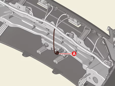
Disconnect the lamp connector (A).
|
| 3.
|
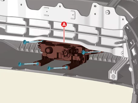
Remove the lamp (A) after removing the screws.
|
| 1.
|
Install in the reverse order of removal.
|
Fog Lamp Replacement
| 1.
|
Remove the head lamp.
(Refer to Light & Vision System - "Head Lamp")
|
The fog lamp cannot be replaced individually due to included in the head lamp.
If necessary,
replace the headlamp.
|
|
Hazard Lamp Switch Removal and Installation
| 1.
|
Remove the crash pad air vent. [Passenger's side]
(Refer to Crash Pad - "Crash Pad Air Vent")
|
| 2.
|
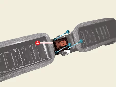
Remove the hazard lamp switch (A) after removing the screws.
|
| 1.
|
Install in the reverse order of removal.
|
Head Lamp Removal and Installation
Head Lamp
| 1.
|
Remove the front bumper assembly.
(Refer to Front & Rear Bumper - "Front Bumper
Assembly")
|
| 2.
|
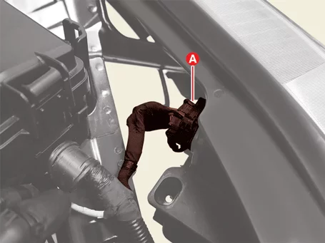
Disconnect the lamp connector (A).
|
| 3.
|
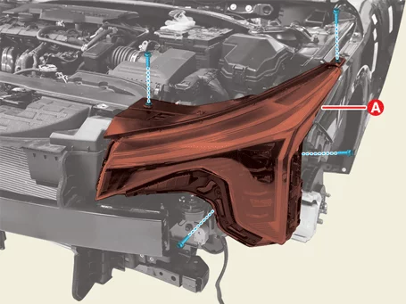
Remove the lamp (A) after removing the bolts.
|
Tightening torque :
2.9 - 5.9 N·m (0.3 - 0.6 kgf·m, 2.2 - 4.3 lb·ft, 26.0 - 52.1 lb·in)
|
|
| 1.
|
Install in the reverse order of removal.
|
| 2.
|
Perform the head lamp / fog lamp aiming procedure when replacing the head lamp assembly.
(Refer to Head Lamp - "Adjustment")
|
Head Lamp Replacement
Absorbent
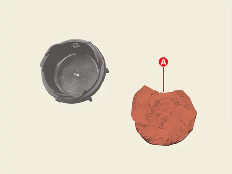
| 1.
|
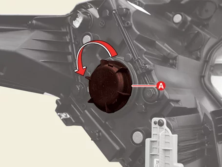
Remove the dust cap (A) by turning in the counterclockwise direction.
|
| 2.
|
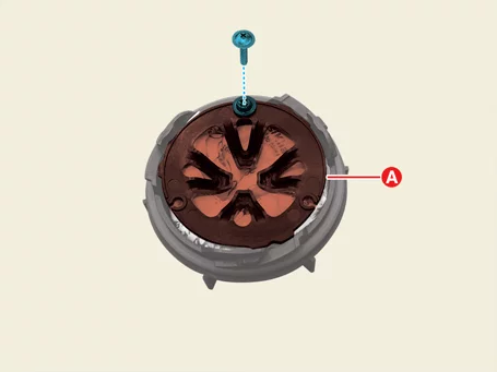
Remove the absorbent bracket (A) after removing the screw.
|
| 3.
|
Replace the absorbent (A).
|
Head Lamp Adjustment
|
•
|
This video was created using 3D graphics to help understand the vehicle
maintenance manual.
|
|
•
|
There may be some differences from actual vehicles.
|
|
•
|
The location and repair procedures of the parts may vary depending on vehicle
model, model year,
region, and specifications.
|
|
•
|
Check the KDS Guide for detailed information on how to use the KDS.
|
|
•
|
Check the manual for detailed maintenance procedures.
|
|
•
|
Unauthorized reproduction, distribution, or sharing of this video is
prohibited.
|
|
Headlamp / Fog Lamp Aiming
(Click to play)

Video: Headlamp / Fog Lamp Aiming - For
Maxico
Headlamp / Fog Lamp Aiming
| 1.
|
Alternately turn the adjusting gear to adjust the headlamp / fog lamp aiming. If beam-setting
equipment
is not available, proceed as follows.
| (1)
|
Inflate the tires to the specified pressure and remove any loads from the
vehicle except the
driver, spare tire, and tools.
|
| (2)
|
The vehicle should be placed on a flat floor.
|
| (3)
|
Check if there is something wrong with the suspension spring.
|
| (4)
|
Clean the headlamp lens.
|
|
| 2.
|
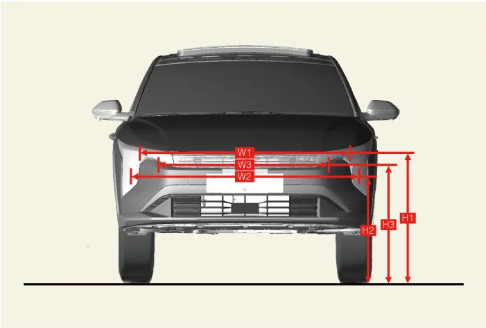
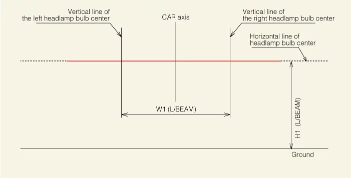
Draw vertical lines (Vertical lines passing through respective head lamp centers) and a
horizontal line
(Horizontal line passing through center of head lamps) on the screen.
H1 : Height between the headlamps bulb center and ground
(Low
beam)
H2 : Height between the headlamps bulb center and ground
(High
beam)
H3 : Height between the fog lamps bulb center and ground
W1 : Distance between the headlamp bulb center (Low
beam)
W2 : Distance between the headlamp bulb center (High
beam)
W3 : Distance between the fog lamp bulb center
Type
|
Vehicle Condition
|
H1
|
H2
|
H3
|
W1
|
W2
|
W3
|
Possible Cause
|
Standard
(Standard headlamp)
|
Empty
|
646
|
579
|
-
|
1,540
|
1,549
|
-
|
All DIM in mm
|
1 person on-board
|
637
|
570
|
Standard
(Option headlamp)
|
Empty
|
656
|
602
|
640
|
1,512
|
1,529
|
1,095
|
1 person on-board
|
647
|
593
|
631
|
GT line
(Standard headlamp)
|
Empty
|
651
|
584
|
-
|
1,486
|
1,501
|
-
|
1 person on-board
|
642
|
575
|
GT line
(Option headlamp)
|
Empty
|
661
|
607
|
645
|
1,486
|
1,501
|
1,095
|
1 person on-board
|
652
|
598
|
636
|
|
•
|
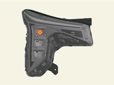
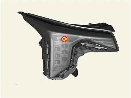
With the head lamp and battery in normal condition, aim the
head lamps so the brightest
portion falls on the horizontal and vertical lines.
|
|
•
|
Headlamp aiming point
Standard
|
Option
|
|
|
|
|
|
•
|
Fog lamp aiming point
Option
|
|
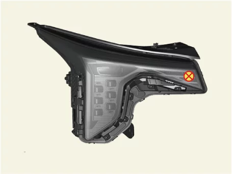
|
|
|
|
| 3.
|
Draw a horizontal line at 0% from the headlamp ground clearance. [Visually Optically aimed using the Right side of the low beam
(VOR) type
only]
|
| 4.
|
If a head light leveling device is installed, set the head light leveling device switch to 0.
|
| 5.
|
Turn the low beam on without driver aboard.
|
A : 3 m / 6 m / 9 m
B (1% of A) : 30 mm / 60 mm / 90 mm
|
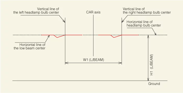
|
•
|
The low beam cut-off line should be projected as shown in the
picture.
|
|
•
|
When aiming the low beam, vertical aiming should be adjusted
after adjusting the
horizontal aiming.
|
|
•
|
Headlamp adjust point
A : Vertical (High/Low
beam)
B : Horizontal (High/Low
beam)
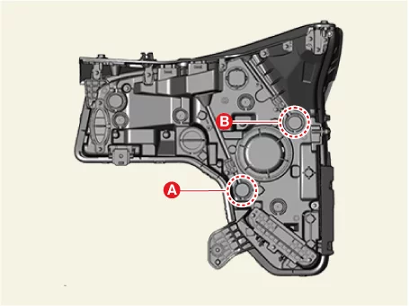
|
|
|
| 6.
|
Turn the high beam on without driver aboard.
|
A : 3 m / 6 m / 9 m
B (3% of A) : 90 mm / 180 mm / 270 mm
C (1% of A) : 30 mm / 60 mm / 90 mm
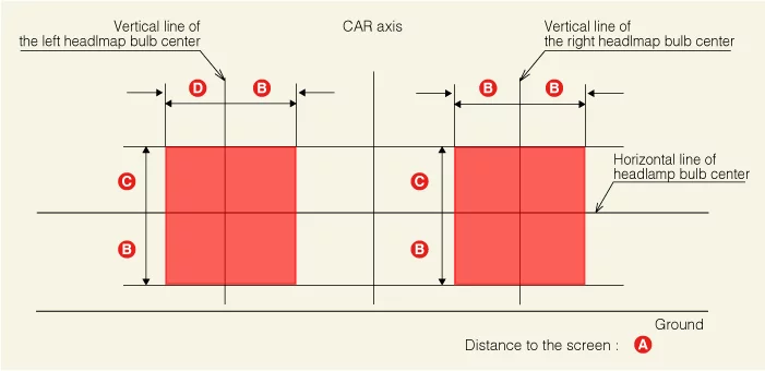
D (1.5% of A) : 45 mm / 90 mm / 180 mm
|
|
•
|
The hot zone should be projected in the allowable range shown
in the picture.
|
|
•
|
If the HOT ZONE range of the high beam is out of regulation
after adjusting the low beam,
the product defect may be the cause. In such cases, exchange it
for a new one after checking
whether it is within the acceptable range.
|
|
|
| 7.
|
Turn the fog lamp on without driver aboard.
|
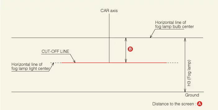
A : 3 m / 6 m / 9 m
B (2% of A) : 60 mm / 120 mm / 180 mm
|
|
•
|
The fog lamp cut-off line should be projected as shown in the
picture.
|
|
•
|
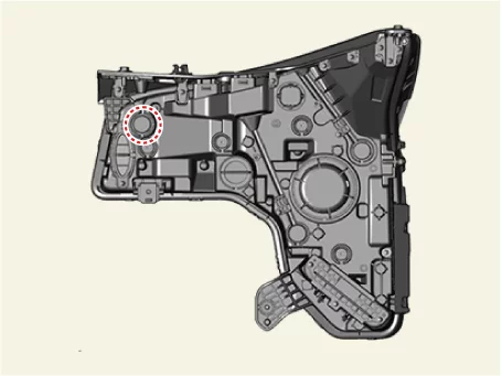
Fog lamp adjust point
|
|
|
High Mounted Stop Lamp Removal and Installation - 4DR
| 1.
|
Remove the package tray trim.
(Refer to Luggage Trim - "Package Tray Trim")
|
| 2.
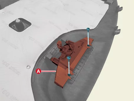
|
Remove the high mounted stop lamp (A) after removing the screws.
|
| 1.
|
Install in the reverse order of removal.
|
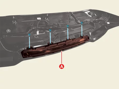
High Mounted Stop Lamp Removal and Installation - 5DR
| 1.
|
Remove the rear spoiler under cover.
(Refer to Body Side Molding - "Rear Spoiler")
|
| 2.
|
Remove the high mounted stop lamp (A) after removing the screws.
|
| 1.
|
Install in the reverse order of removal.
|
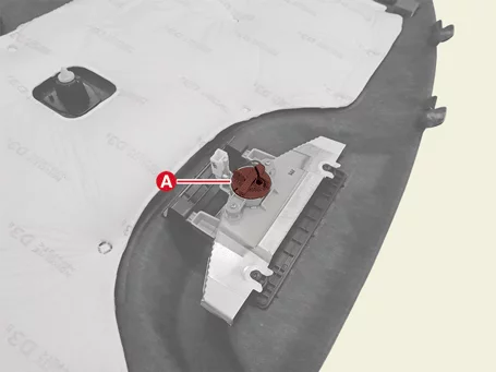
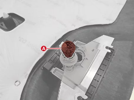
High Mounted Stop Lamp Replacement
| 1.
|
Remove the bulb socket (A).
|
| 2.
|
Replace the bulb (A).
|
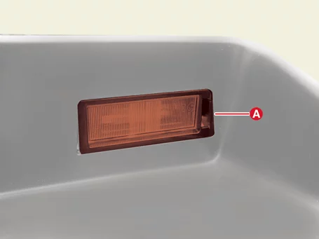
License Lamp Removal and Installation
|
The indication below represents the location of a clip or fastener.

|
| 1.
|
Disconnect the battery negative (-) terminal.
|
| 2.
|
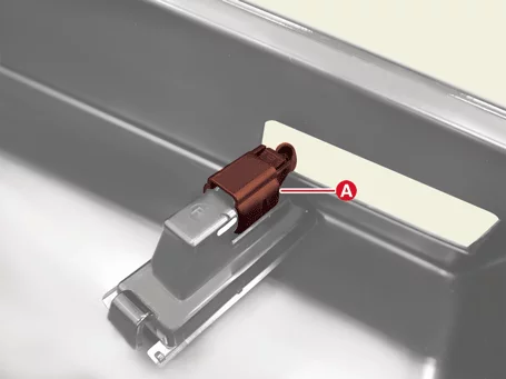
Remove the license lamp (A).
|
| 3.
|
Disconnect the lamp connector (A).
|
| 1.
|
Install in the reverse order of removal.
|
Luggage Lamp Removal and Installation - 4DR
|
The indication below represents the location of a clip or fastener.
|
| 1.
|
Disconnect the battery negative (-) terminal.
|
| 2.
|
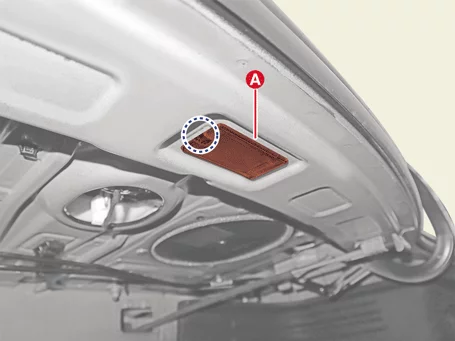
Remove the luggage lamp (A).
|
| 3.
|
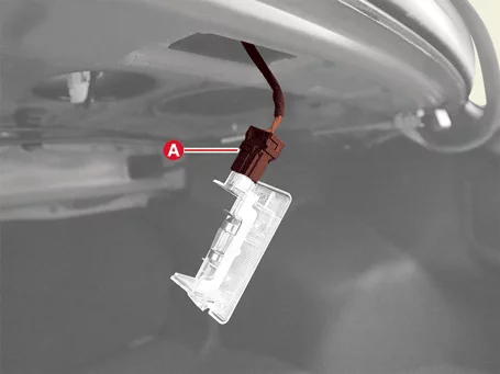
Disconnect the lamp connector (A).
|
| 1.
|
Install in the reverse order of removal.
|
Luggage Lamp Removal and Installation - 5DR
| 1.
|
Disconnect the battery negative (-) terminal.
|
| 2.
|
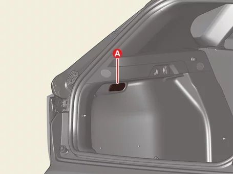
Remove the luggage lamp (A).
|
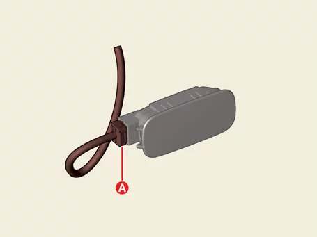
| 3.
|
Disconnect the lamp connector (A).
|
| 1.
|
Install in the reverse order of removal.
|
Mood Lamp Removal and Installation
|
The indication below represents the location of a clip or fastener.
|
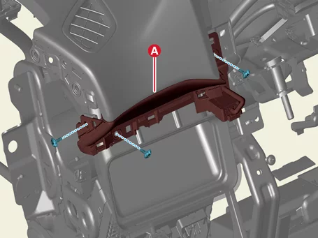
Crash Pad Mood Lamp [Driver's Side]
| 1.
|
Remove the integrated monitor or instrument cluster.
Integrated monitor:
(Refer to
Infotainment System - "Integrated Monitor")
Instrument cluster:
(Refer to
Infotainment System - "Instrument Cluster")
|
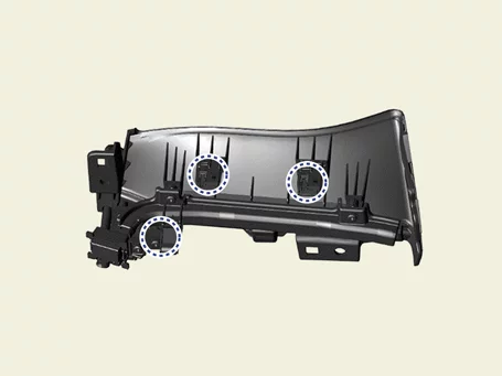
| 2.
|
Remove the lamp (A) after removing the screws.
|
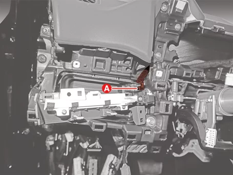
| 3.
|
Disconnect the lamp connector (A).
|
Crash Pad Mood Lamp [Passenger's Side]
| 1.
|
Remove the integrated monitor.
(Refer to Infotainment System - "Integrated Monitor")
|
| 2.
|
Remove the lamp (A) after removing the screws.
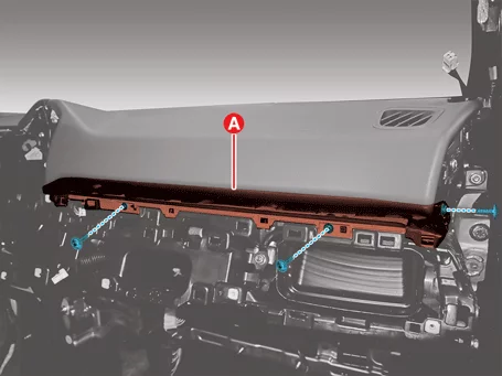
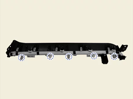
|
| 3.
|
Disconnect the lamp connector (A).
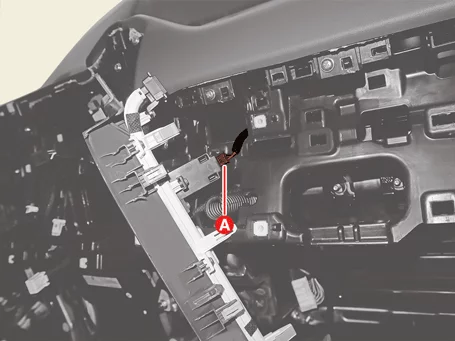
|
Mood Lamp Unit
| 1.
|
Remove the crash pad center panel.
(Refer to Crash Pad - "Crash Pad Panel")
|
| 2.
|
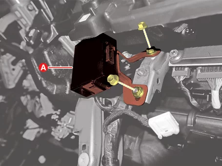
Disconnect the unit connector (A).
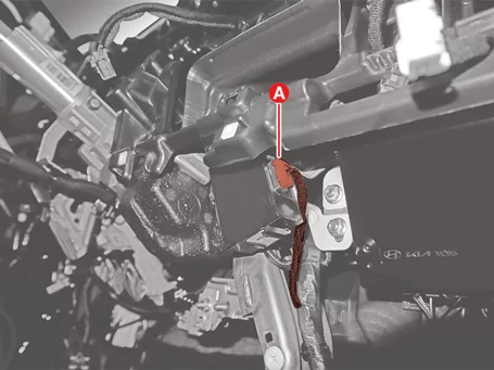
|
| 3.
|
Remove the unit (A) after removing the nuts.
|
Tightening torque :
3.9 - 5.9 N·m (0.4 - 0.6 kgf·m, 2.9 - 4.3 lb·ft, 34.7 - 52.1 lb·in)
|
|
| 1.
|
Install in the reverse order of removal.
|
| 2.
|
Perform Over The Air (OTA) controller S/W update with KDS. [Mood
lamp
unit only]
(Refer to Security & Vehicle Ignition System - "Over The
Air
(OTA)")
|
Overhead Console Lamp Removal and Installation
| 1.
|
Disconnect the battery negative (-) terminal.
|
| 2.
|
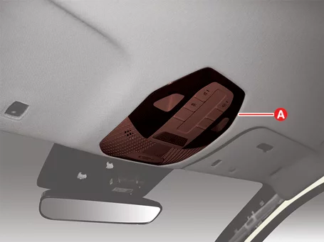
Remove the overhead console lamp (A).
|
| 3.
|
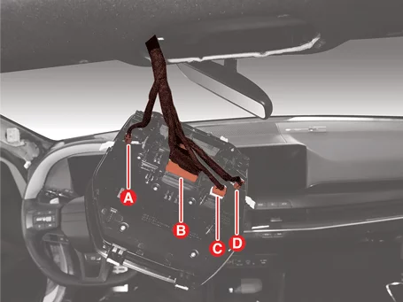
Disconnect the connectors (A, B, C, D).
A : Hands-free mic connector [LH]
B : Overhead console lamp connector
C : Sunroof switch connector
D : Hands-free mic connector [RH]
|
| 1.
|
Install in the reverse order of removal.
|
Rear Combination Lamp Removal and Installation - 4DR
Outside Rear Combination Lamp
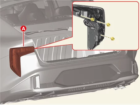
| 1.
|
Disconnect the battery negative (-) terminal.
|
| 2.
|
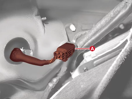
Disconnect the lamp connector (A).
|
| 3.
|
Remove the lamp (A) after removing the nuts.
|
Tightening torque:
2.5 - 3.9 N·m (0.25 - 0.40 kgf·m, 1.8 - 2.9 lb·ft, 21.7 - 34.7 lb·in)
|
|
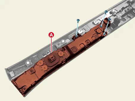
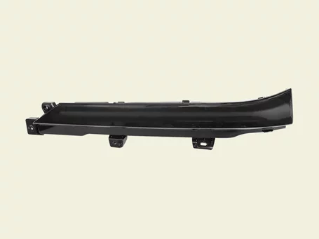
Inside Rear Combination Lamp
| 1.
|
Remove the trunk lid garnish.
(Refer to Body Side Molding - "Trunk Lid Garnish")
|
| 2.
|
Remove the lamp (A) after removing the screws.
|
| 1.
|
Install in the reverse order of removal.
|
Rear Combination Lamp Removal and Installation - 5DR
|
The indication below represents the location of a clip or fastener.
|
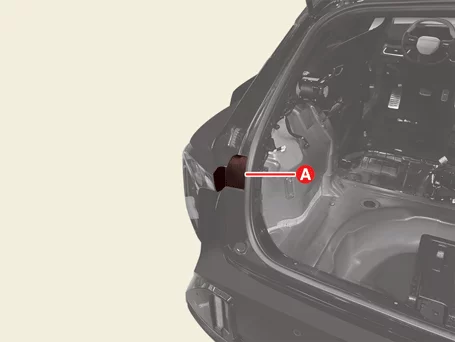
Outside Rear Combination Lamp
| 1.
|
Disconnect the battery negative (-) terminal.
|
| 2.
|
Remove the cover (A).
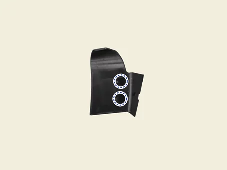
|
| 3.
|
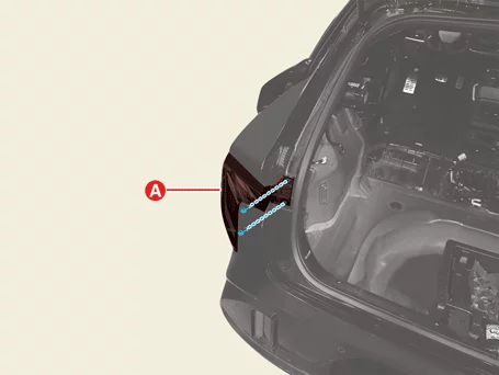
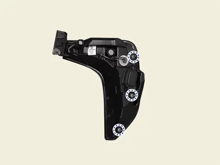
Remove the lamp (A) after removing the bolts.
|
Tightening torque:
2.5 - 3.9 N·m (0.25 - 0.40 kgf·m, 1.8 - 2.9 lb·ft, 21.7 - 34.7 lb·in)
|
|
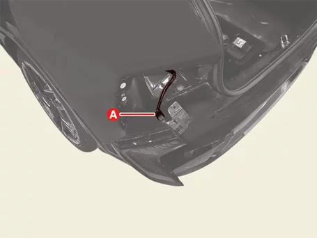
| 4.
|
Disconnect the lamp connector (A).
|
Inside Rear Combination Lamp
| 1.
|
Remove the tailgate garnish.
(Refer to Body Side Molding - "Tailgate Garnish")
|
| 2.
|
Remove the lamp (A) after removing the screws.
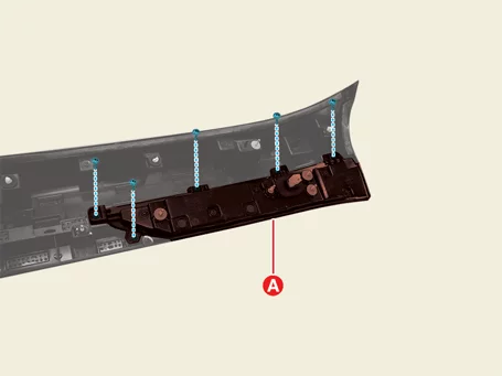
|
| 1.
|
Install in the reverse order of removal.
|
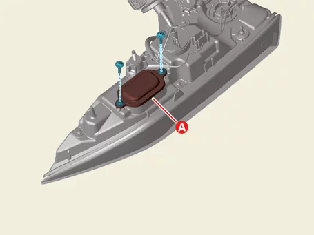
Rear Combination Lamp Replacement
Absorbent
| 1.
|
Remove the dust cap (A) after removing the screws.
|
| 2.
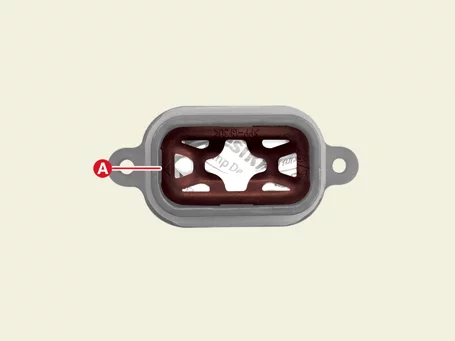
|
Remove the absorbent bracket (A).
|
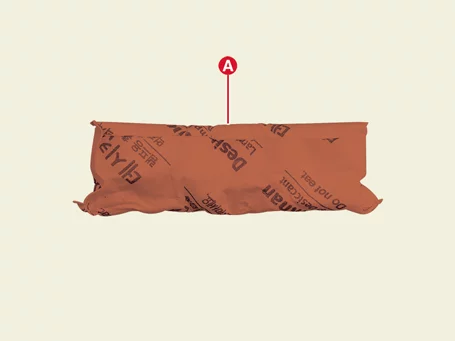
| 3.
|
Replace the absorbent (A).
|
Bulb
| 1.
|
Remove the socket (A, B).
A : Stop lamp
B : Turn signal lamp
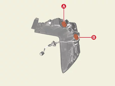
|
| 2.
|
Replace the bulb (A).
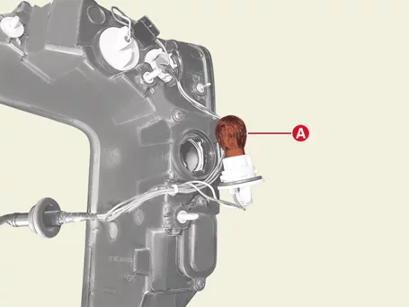
|
Room Lamp Removal and Installation
|
The indication below represents the location of a clip or fastener.
|
| 1.
|
Disconnect the battery negative (-) terminal.
|
| 2.
|
Remove the lamp (A).
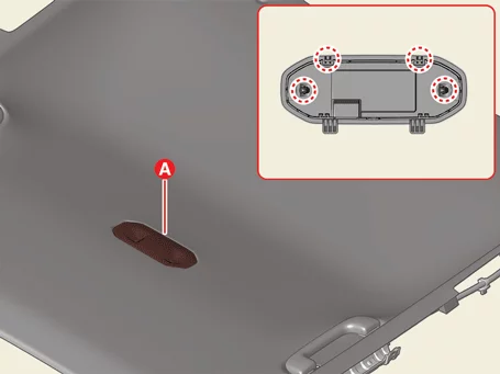
|
| 3.
|
Disconnect the lamp connector (A).
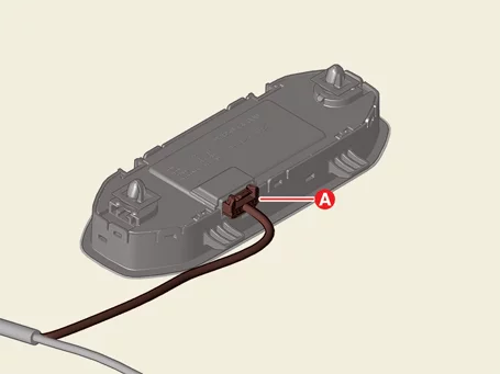
|
| 1.
|
Install in the reverse order of removal.
|
Trunk Lamp Removal and Installation
|
The indication below represents the location of a clip or fastener.
|
| 1.
|
Disconnect the battery negative (-) terminal.
|
| 2.
|
Remove the trunk lamp (A).
|
| 3.
|
Disconnect the lamp connector (A).
|
| 1.
|
Install in the reverse order of removal.
|
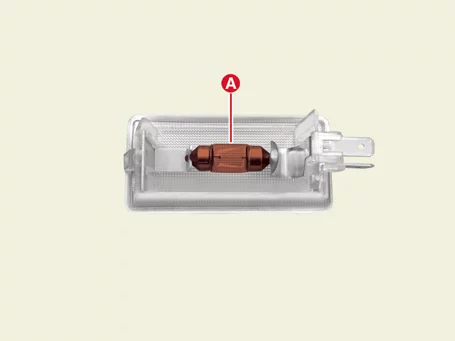
Trunk Lamp Replacement
| 1.
|
Replace the bulb (A).
|
Turn Signal Lamp Removal and Installation
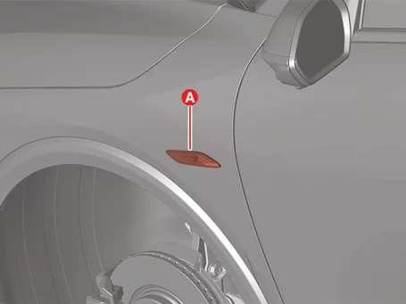
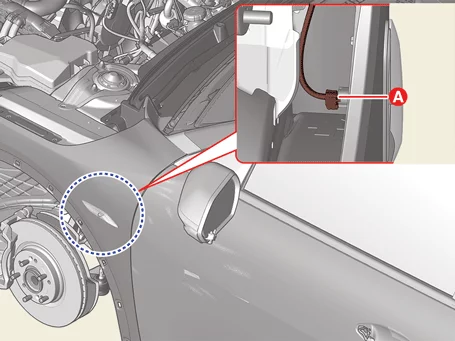
Side Repeater Lamp [Fender Side]
| 1.
|
Disconnect the battery negative (-) terminal.
|
| 2.
|
Remove the lamp (A).
|
| 3.
|
Disconnect the lamp connector (A).
|
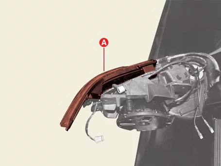
Side Repeater Lamp [Outside Mirror Side]
| 1.
|
Remove the outside mirror lower cover.
(Refer to Mirror - "Outside Mirror Assembly")
|
| 2.
|
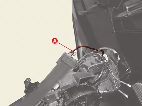
Remove the lamp (A).
|
| 3.
|
Disconnect the lamp connector (A).
|
| 1.
|
Install in the reverse order of removal.
|
Vanity Lamp Removal and Installation
| 1.
|
Disconnect the battery negative (-) terminal.
|
| 2.
|
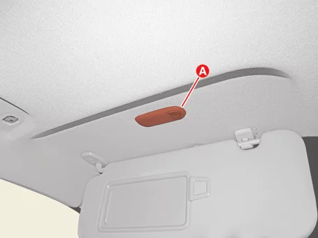
Remove the vanity lamp (A).
|
| 3.
|
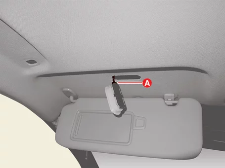
Disconnect the lamp connector (A).
|
| 1.
|
Install in the reverse order of removal.
|
Other information:
Kia K4 (CL4) 2025-2026 Service Manual: Inside rearview mirror
Adjust the inside rearview mirror so that you can view the entire rear window clearly from your driving position. Ensure this adjustment is finalized before you begin your journey in the Kia K4.
To maintain a clear view, avoid placing bulky items, boxes, or passengers in the rear seat or cargo area that could obstruct the rear window visibility.
WARNING
Mirror adjustment
For your safety, never attempt to adjust the rearview mirror while the Kia K4 is in motion.
Kia K4 (CL4) 2025-2026 Service Manual: High Beam Assist (HBA)
The High Beam Assist (HBA) feature in your Kia K4 provides automated convenience by switching between high and low beams based on the detection of oncoming vehicles, preceding taillights, and ambient road brightness. This helps maximize your vision without blinding other road users.
Detection sensor
The system relies on a high-resolution forward-facing camera.