Contents:
Description and Operation
The Motor Driven Power Steering (MDPS) system uses an electric motor to assist the steering force and it is an
engine operation-independent steering system.
The MDPS control module controls the motor operation according to information received from each sensor and CAN
(Controller Area Network), resulting in more precise and timely control of steering assist than conventional
engine-driven hydraulic systems.
Each component of the MDPS system can be inspected individually, but only some parts can be replaced, so it
should not be disassembled except for replaceable parts on the shop manual.
The MDPS warning light turns on when the vehicle is started and turns off after 3 seconds if there is no defect
in the system. If the warning light remains on after 3 seconds or turns on while driving, check the MDPS system.
Note With Regard to Diagnosis
Trouble factor
|
Check item
|
Trouble symptom
|
Explanation
|
Note
|
Drop, impact, and overload
|
Motor
|
Abnormal noise
|
Visible or invisible damage may occur. The steering wheel may pull to one side when
dropped parts
are used. Precise parts of motor / ECU are sensitive to vibration and impact. Overload may cause
unexpected
damage.
|
Do not use the impacted MDPS.
|
ECU
|
Circuit damage
|
Do not overload each part.
|
Wrong welding point
|
|
Broken PCB
|
|
Damaged precise parts
|
|
Torque sensor
|
Insufficient steering effort
|
Overload to INPUT shaft can cause malfunction of the torque sensor
|
Do not impact the connecting parts (when inserting and torquing).
|
Use the specified tool to remove the steering wheel. (Do not hammer on it.)
|
Do not use the impacted MDPS.
|
Shaft
|
Insufficient steering effort (Uneven between LH and RH)
|
|
Do not use impacted MDPS
|
Pull/Dent
|
Harness
|
Malfunctioning
|
Disconnection between harness connecting portion and harness
|
Do not overload the harness
|
Power operation impossible
|
Malfunction of MDPS
|
Abnormal storage temperature
|
Motor/ECU
|
Abnormal steering effort by improper operation of the motor/ECU
|
Waterproof at normal condition
|
Maintain normal storage temperature and humidity.
|
Even a slight moisture can cause malfunction in precise parts of the motor / ECU
|
Avoid submerging in water.
|
|
•
|
Do not impact the electronic parts. If they are dropped or impacted, replace
them with new ones.
|
|
•
|
Avoid heat and moisture to the electronic parts.
|
|
•
|
Do not contact the connect terminal to avoid deformation and static
electricity.
|
|
•
|
Do not impact the motor and torque sensor parts. If they are dropped or
impacted, replace them
with new ones.
|
|
•
|
The connector should be disconnected or connected with ignition OFF.
|
|
On Vehicle Inspection
| 1.
|
Diagnostic equipment (KDS) can be used to diagnose fault parts quickly. (Refer to "DTC
Diagnostic Guide")
| (1)
|
Self diagnosis : Inspection and display fault code (DTC)
(Refer to DTC guide when fault code is found.)
|
| (2)
|
S/W Management : Controlling other features including system option setting and
zero point
adjustment.
(S/W Management → EPS - Power Steering → Steering Angle Sensor(SAS) Calibration
(S/W Management → EPS - Power steering → Set the steering feel torque to zero)
(S/W Management → EPS - Power steering → MDPS Tuning Data Setting)
|
Refer to the KDS screen for operating conditions and details
|
|
|
If the MDPS warning light does not illuminate, the following symptoms are normal :
|
•
|
Immediately after starting the engine, there is no temporary auxiliary steering
force during the
MDPS system self-diagnosis time (about 2 seconds), but this is not a
malfunction.
|
|
•
|
Noise due to relay connection on engine On or Off, but this is normal operating
sound.
|
|
•
|
Noise due to motor rotation during steering or low-speed driving, but this is
normal operating
sound.
|
|
Steering Angle Sensor (SAS) Location Information
C-MDPS : MDPS Unit (Refer to "DTC Diagnostic Guide")
Noise / Malfunction Repair Guide
Symptoms
|
Possible causes and inspection
|
Repair method
|
Abnormal noise
|
1. An abnormal noise from MDPS column and housing
|
–
|
Column & housing partial part exchange
|
–
|
Check for the same noise after removing surrounding parts
|
–
|
Replace motor when checking motor noise
|
Abnormal noise
|
1. Check the handle and surrounding parts
|
Check the noise from the parts
|
–
|
Check for DAB wiring harness and DAB, clock spring, multi-function switch
|
–
|
Check the parts
|
2. C - MDPS mounting check
|
Check the cowl mounting condition
|
–
|
Remove the cowl mounting bolt, then reassemble it
|
(C-MDPS lower end fixing through-bolt included
|
3. Check the universal joint mounting bolt
|
If the bolt is worn, replace the universal joint mounting bolt
|
–
|
After removing and installing the universal joint completely, check the noise again.
|
4. Check the column moves when steering while the vehicle is stopped
|
Secure clearance between parts
|
–
|
Check the main wiring connected to MDPS / Spacing between parts around shroud/ Check friction
|
–
|
Check the wiring and column for moves and clearance between parts
|
Cautions when handling MDPS (Motor Driven Power Steering)
| 1.
|
Internal damage may occur if parts fall, impact, or excessive load occurs.
→ If it is dropped or impacted, replace it with a new one.
|
| 2.
|
Tightening the steering wheel with excessive force can distort the center of the torque sensor.
→Tighten with moderate force.
|
| 3.
|
Be careful not to apply excessive force as the wiring may be damaged by deformation when
attaching/detaching the connector.
→Do not use excessive connector insertion/removal.
|
| 4.
|
Careful storage and replacement of partial parts under abnormal temperature and humidity
conditions.
|
MDPS Power Pack Assembly On Vehicle Inspection
| 1.
|
The MDPS system can be more quickly diagnosed for problems by using the KDS (Refer to "DTC
guide").
| (1)
|
Self diagnosis : Inspects and displays diagnostic trouble code (DTC)
(Refer to DTC guide when fault code is found.)
|
| (2)
|
Sensor data : Checking the system input/output data state
|
| (3)
|
Forced operation : Check the system operating condition
|
| (4)
|
Additional function : Controlling other features including system option
setting and zero point
adjustment
|
|
Refer to the KDS screen for operating conditions and details
|
|
If there is any DTC about the MDPS motor, inspect the wiring and connectors and
then replace the
MDPS power pack if there is no problem.
(Refer to Motor Driven Power Steering (MDPS) -
"MDPS Power Pack
Assembly")
|
|
MDPS Power Pack Assembly Removal and Installation
| 1.
|
Remove the steering column assembly.
(Refer to Motor Driven Power Steering - "Steering Column
Assembly")
|
| 2.
|
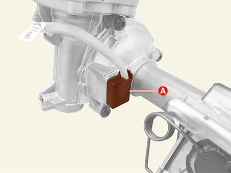
Separate the connector cap (A).
|
| 3.
|
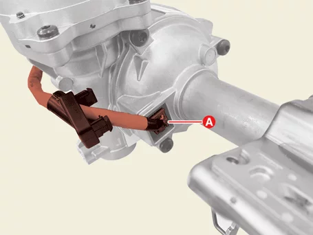
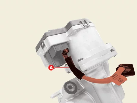
Disconnect the MDPS power pack assembly connectors (A).
|
| 4.
|
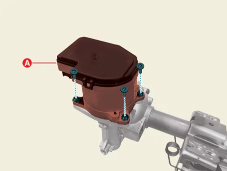
Remove the MDPS power pack assembly (A) after removing the screws.
|
Tightening torque :
7.8 - 11.8 N·m (0.8 - 1.2 kgf·m, 5.8 - 8.7 lb·ft)
|
|
| 1.
|
Install in reverse order of removal.
|
•
|
Install to the specified torque.
|
|
•
|
Dropping the power pack assembly can cause internal damage. In
this case, use it after
inspection.
|
|
•
|
Install the power pack assembly in the correct direction as
below.
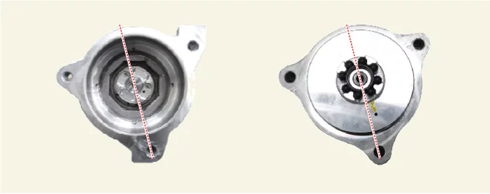
|
|
|
| 2.
|
Perform in the order below with the KDS.
(S/W Management → EPS - Power steering → MDPS Tuning Data Setting)
(S/W Management → EPS - Power Steering → Steering Angle Sensor(SAS) Calibration
(S/W Management → EPS - Power steering → Set the steering feel torque to zero)
|
Refer to the KDS screen for operating conditions and details
|
|
Steering Column Assembly Components and Components Location
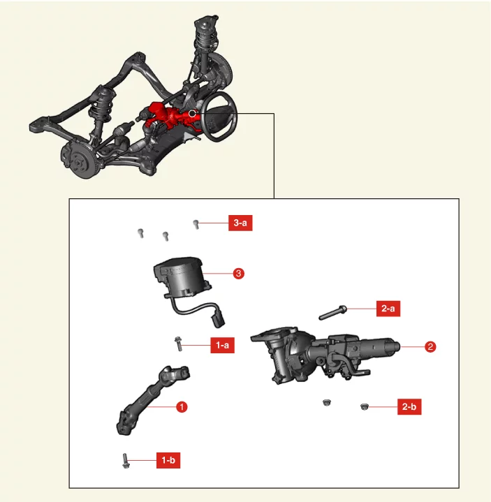
1. Universal Joint Assembly
1-a. 49.0 -
58.8 N·m
(5.0 - 6.0 kgf·m, 36.2 - 43.4 lb·ft)
1-b. 49.0 - 58.8 N·m (5.0 - 6.0 kgf·m, 36.2 - 43.4
lb·ft)
2.
Steering Column Assembly
2-a. 53.9 - 58.8 N·m (5.5 - 6.0 kgf·m, 39.8 - 43.4 lb·ft)
2-b. 24.5 -
29.4 N·m
(2.5 - 3.0 kgf·m, 18.1 - 21.7 lb·ft)
|
3. MDPS Power Pack Assembly
3-a. 7.8 - 11.8
N·m
(0.8 - 1.2 kgf·m, 5.8 - 8.7 lb·ft)
|
Steering Column Assembly On Vehicle Inspection
| 1.
|
Check if the steering column is deformed or damaged.
|
| 2.
|
Check the universal joint bearing for damage or wear.
|
| 3.
|
Check if the steering column tilt bracket is cracked or damaged.
|
Steering Column Assembly Removal and Installation
|
•
|
This video was created using 3D graphics to help understand the vehicle
maintenance manual.
|
|
•
|
There may be some differences from actual vehicles.
|
|
•
|
The location and repair procedures of the parts may vary depending on vehicle
model, model year,
region, and specifications.
|
|
•
|
Check the KDS Guide for detailed information on how to use the KDS.
|
|
•
|
Check the manual for detailed maintenance procedures.
|
|
•
|
Unauthorized reproduction, distribution, or sharing of this video is
prohibited.
|
|
Steering Column Assembly Removal
(Click to play)

Video: Steering Column Assembly Removal
| 1.
|
Align the steering wheel straight.
|
| 2.
|
Disconnect the battery negative ( - ) terminal.
|
| 3.
|
Remove the multi-function switch.
(Refer to Body - "Multi-function Switch")
|
| 4.
|
Remove the central communication unit (CCU).
(Refer to Body - "Central Communication Unit (CCU)")
|
| 5.
|
Separate the universal joint assembly (A) after removing the bolt.
|
Tightening torque :
49.0 - 58.8 N·m (5.0 - 6.0 kgf·m, 36.2 - 43.4 lb·ft)
|
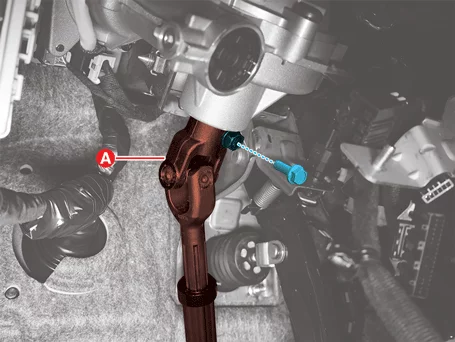
|
Do not reuse the universal joint assembly bolt.
|
|
| 6.
|
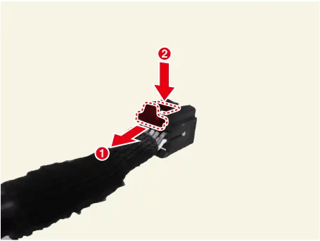
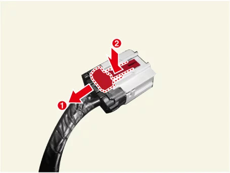
Disconnect the motor driven power steering (MDPS) power pack assembly connectors (A).
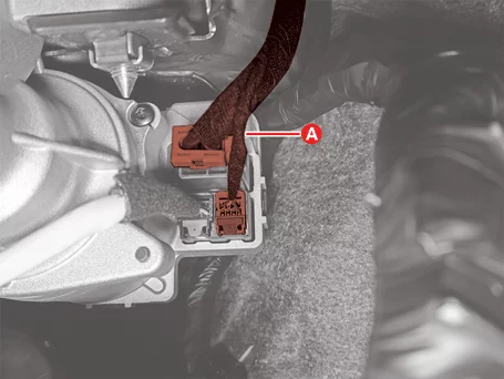
|
Disconnect the connector as in the procedure below.
|
|
| 7.
|
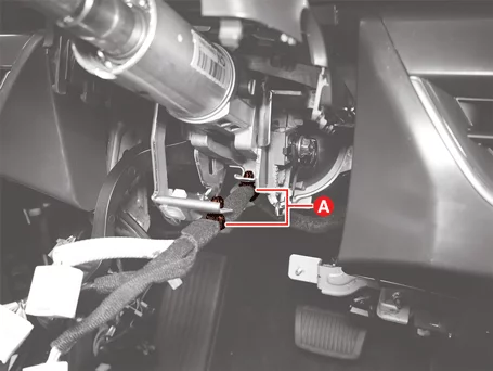
Remove the wiring clips (A).
|
| 8.
|
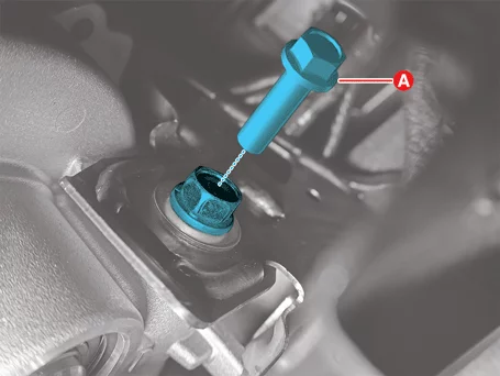
Remove the column housing bolt (A).
|
Tightening torque :
53.9 - 58.8 N·m (5.5 - 6.0 kgf·m, 39.8 - 43.4 lb·ft)
|
|
| 9.
|
Remove the column housing assembly (A) after removing the nuts.
|
Tightening torque :
24.5 - 29.4 N·m (2.5 - 3.0 kgf·m, 18.1 - 21.7 lb·ft)
|
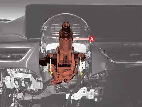
|
| 1.
|
Install in the reverse order of removal.
|
•
|
Install to the specified torque.
|
|
•
|
When assembling the steering column, insert the dowel pin (A)
well into the MDPS bracket
groove (B).
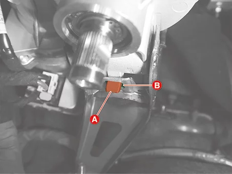
|
|
•
|
Tighten the steering gear joint by firmly inserting it into the
steering gearbox pinion
shaft during installation.
|
|
•
|
Make sure that the universal joint bolt head faces the driver
when installing.
|
|
|
| 2.
|
Perform in the order below with the KDS.
(S/W Management → EPS - Power steering → MDPS Tuning Data Setting)
(S/W Management → EPS - Power Steering → Steering Angle Sensor(SAS) Calibration
(S/W Management → EPS - Power steering → Set the steering feel torque to zero)
|
Refer to the KDS screen for operating conditions and details
|
|
Universal Joint Assembly Components and Components Location
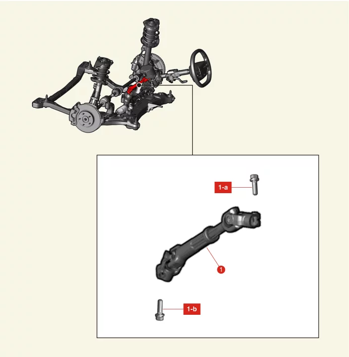
1. Universal Joint Assembly
1-a. 49.0 -
58.8 N·m
(5.0 - 6.0 kgf·m, 36.2 - 43.4 lb·ft)
1-b. 49.0 - 58.8 N·m (5.0 - 6.0 kgf·m, 36.2 - 43.4
lb·ft)
|
|
Universal Joint Assembly On Vehicle Inspection
| 1.
|
Check the bolts tightening condition of the universal joint.
|
| 2.
|
Check if the universal joint is damaged or worn.
|
Universal Joint Assembly Removal and Installation
| 1.
|
Align the steering wheel straight.
|
| 2.
|
Disconnect the battery negative ( - ) terminal.
|
| 3.
|
Fix the steering wheel (A) by using a suitable tool.
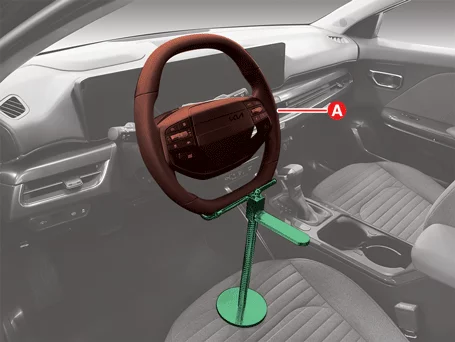
|
When the steering wheel moves, the cable inside the clock spring may be
damaged, so keep it
neutral.
|
|
| 4.
|
Remove the central communication unit (CCU).
(Refer to Body - "Central Communication Unit (CCU)")
|
| 5.
|
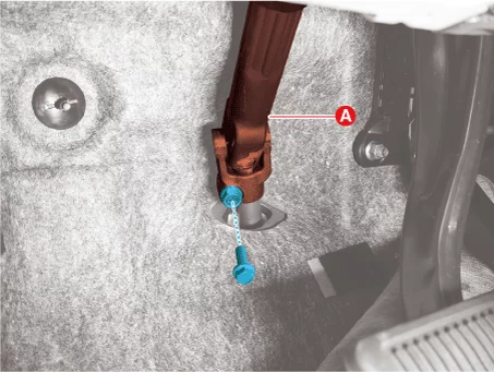
Separate the universal joint assembly (A) after removing the bolt.
|
Tightening torque :
49.0 - 58.8 N·m (5.0 - 6.0 kgf·m, 36.2 - 43.4 lb·ft)
|
|
Do not reuse the universal joint assembly bolt.
|
|
| 6.
|
Remove the universal joint assembly (A) after removing the bolt.
|
Tightening torque :
49.0 - 58.8 N·m (5.0 - 6.0 kgf·m, 36.2 - 43.4 lb·ft)
|
|
| 1.
|
Install in the reverse order of removal.
|
•
|
Install to the specified torque.
|
|
•
|
Insert the universal joint assembly securely into the steering
gearbox pinion shaft.
|
|
•
|
Make sure that the universal joint bolt head faces the driver
when installing.
|
|
|
Steering Gearbox Components and Components Location
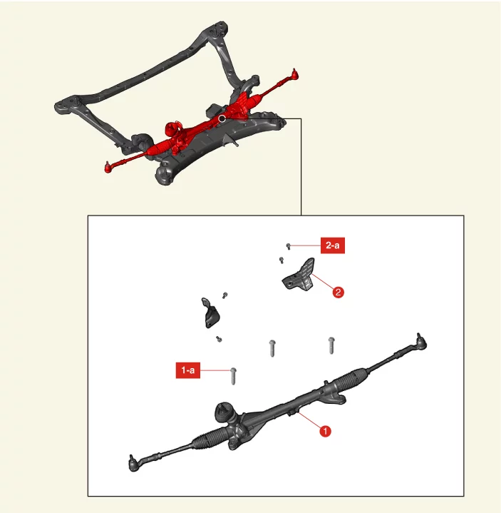
1. Steering Gearbox
1-a. 107.9 -
127.5 N·m
(11.0 - 13.0 kgf·m, 79.6 - 94.0 lb·ft)
2. Heat Protector
2-a. 6.9 - 10.8 N·m (0.7 - 1.1 kgf·m,
5.1 - 8.0
lb·ft, 60.8 - 95.5 lb·in)
|
|
Steering Gearbox Removal and Installation
Tool Name / Number
|
Illustration
|
Description
|
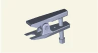
Ball joint puller
09568 - 1S100
|
|
Used for removal of tie rod end and lower arm ball joint
|
| 1.
|
Align the steering wheel straight.
|
| 2.
|
Disconnect the negative ( - ) battery terminal.
|
| 3.
|
Fix the steering wheel (A) by using a suitable tool.
|
If the neutral position of the clock spring is changed by rotating the steering
wheel while the
steering column universal joint is removed, disconnection of the internal cable
of the clock spring
may be folded after installation.
|
|
| 4.
|
Separate the universal joint assembly (A) from the steering gear box after removing the bolt.
|
Tightening torque :
49.0 - 58.8 N·m (5.0 - 6.0 kgf·m, 36.2 - 43.4 lb·ft)
|
|
Do not reuse the universal joint assembly bolt.
|
|
| 5.
|
Remove the front wheel and tires.
(Refer to Suspension System - "Wheel")
|
| 6.
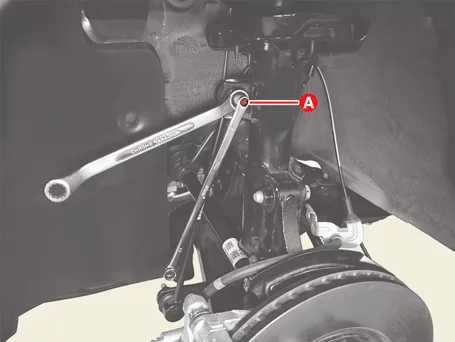
|
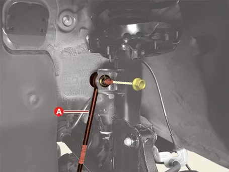
Remove the stabilizer bar link (A) from the front strut assembly after removing the nut.
|
Tightening torque :
98.1 - 117.7 N·m (10.0 - 12.0 kgf·m, 72.3 - 86.8 lb·ft)
|
|
•
|
When removing and installing the stabilizer bar link nut, fix
the outer hexa stud (A) of
the link.
|
|
•
|
Be careful not to damage the boot of the link.
|
|
•
|
Use only a hand tool when removing or installing the stabilizer
bar link nut.
|
|
|
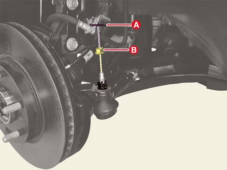
| 7.
|
Separate the tie rod end ball joint from the front knuckle.
| (1)
|
Remove the split pin (A).
|
| (2)
|
Remove the lock nut (B).
|
Tightening torque :
34.3 - 44.1 N·m (3.5 - 4.5 kgf·m, 25.3 - 32.5 lb·ft)
|
|
•
|
Do not reuse the split pin.
|
|
•
|
Do not reuse the lock nut.
|
|
•
|
Be careful not to damage the ball joint boot.
|
|
•
|
Use a hand tool when removing or installing the
lock nut.
|
|
|
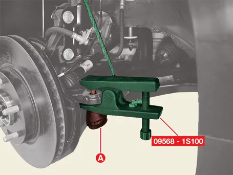
| (3)
|
Separate the tie rod end ball joint (A) using SST (09568 - 1S100).
|
|
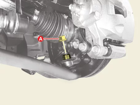
| 8.
|
Separate the lower arm ball joint from the front knuckle.
| (1)
|
Remove the lock nut (A).
|
Tightening torque :
68.6 - 80.4 N·m (7.0 - 8.2 kgf·m, 50.6 - 59.3 lb·ft)
|
|
•
|
Do not reuse the lock nut.
|
|
•
|
Be careful not to damage the ball joint boot.
|
|
•
|
Use a hand tool when removing or installing the
lock nut.
|
|
|
| (2)
|
Separate the lower arm ball joint (A) using SST (09568 - 1S100).
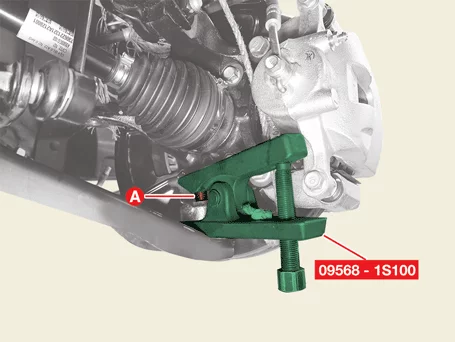
|
|
| 9.
|
Remove the engine room under cover.
G 1.6 T-GDI GAMMA II (Refer to Engine Mechanical System-
"Engine Room
Under Cover")
G 2.0 MPI NU(ATKINSON) (Refer to Engine Mechanical System-
"Engine Room
Under Cover")
|
| 10.
|
Separate the muffler hanger rubber (A) from the front subframe.
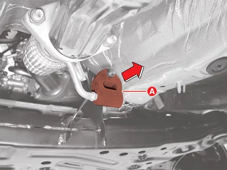
|
| 11.
|
Remove the roll rod support bolt (A).
|
Tightening torque :
107.9 - 127.5 N·m (11.0 - 13.0 kgf·m, 79.6 - 94 lb·ft)
|
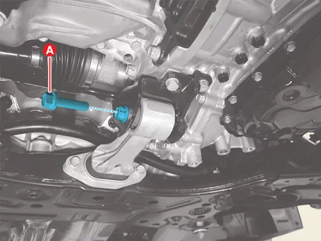
|
| 12.
|
Remove the wheel guard fasteners (A).
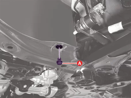
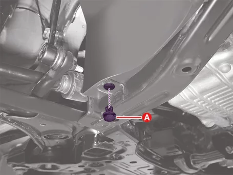
|
| 13.
|
Support the front subframe with a suitable jack (A).
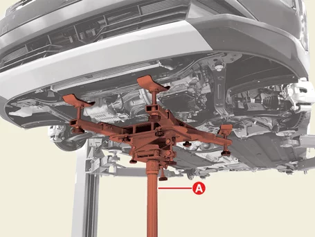
|
Be careful not to lift the vehicle too much. A change in the center of gravity
may cause the
vehicle to fall.
|
|
If a small jack such as a mission jack is used when removing and installing the
subframe, the
subframe may lean to one side and there may be a risk of injury, so use an
appropriately sized jack
to work safely.
|
|
When installing or removing the front subframe bolts and nuts, adjust the table
lift position.
|
|
| 14.
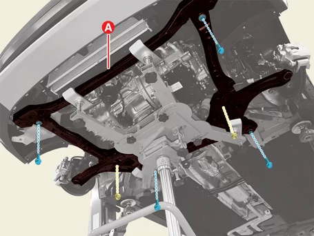
|
Remove the front subframe bolts and nuts (A).
|
Tightening torque :
176.5 - 196.1 N·m (18.0 - 20.0 kgf·m, 130.2 - 144.7 lb·ft)
|
|
| 15.
|
Remove the front subframe by lowering the jack (A).
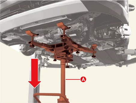
|
Be careful not to interfere with the surrounding parts when removing the front
subframe.
|
|
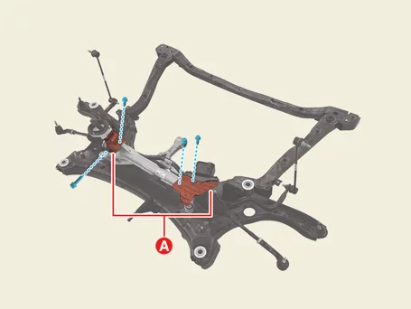
| 16.
|
Remove the steering gear box heat protector (A) after removing the bolts.
|
Tightening torque :
6.9 - 10.8 N·m (0.7 - 1.1 kgf·m, 5.1 - 8.0 lb·ft, 60.8 - 95.5 lb·in)
|
|
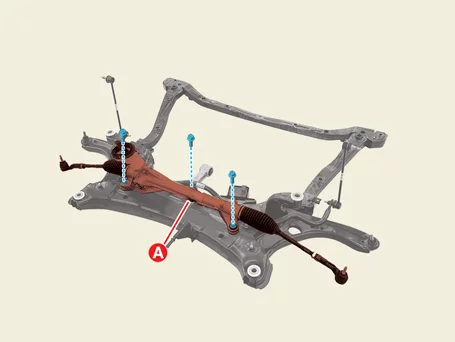
| 17.
|
Remove the steering gear box (A) after removing the bolts.
|
Tightening torque :
107.9 - 127.5 N·m (11.0 - 13.0 kgf·m, 79.6 - 94.0 lb·ft)
|
|
| 1.
|
Install in the reverse order of removal.
|
Install to the specified torque.
|
|
| 2.
|
Check the alignment.
(Refer to Alignment - "Repair Procedures")
|
Steering Gearbox Disassembly and Reassembly
|
•
|
Do not disassemble the steering gear box.
|
|
•
|
When replacing internal parts related to noise/cleanliness/functions other than
simple fastening
parts, the performance of part can not guarantee.
|
|
Bellows
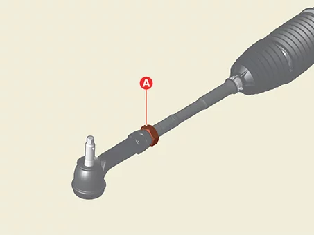
| 1.
|
Loosen the tie rod end lock nut (A) until the tie rod end can rotate.
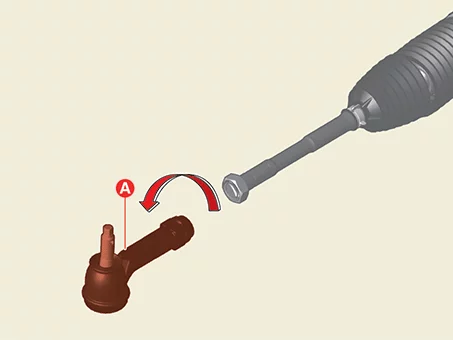
|
| 2.
|
Rotate the tie rod end (A) counterclockwise to remove.
|
| 3.
|
Remove the tie rod end lock nut (A).
|
Tightening torque :
49.0 - 53.9 N·m (5.0 - 5.5 kgf·m, 36.2 - 39.8 lb·ft)
|
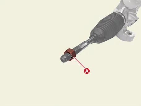
|
| 4.
|
Remove the bellows clamp (A).
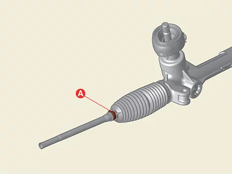
|
| 5.
|
Remove the bellows band (A).
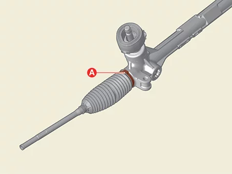
|
•
|
When assembling the bellows, install it with the band and then
assemble.
|
|
•
|
Do not reuse the bellows band.
|
|
|
| 6.
|
Remove the bellows (A) in the direction of the arrow.
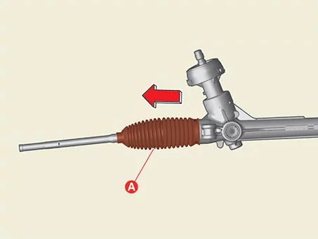
|
Dust cap
| 1.
|
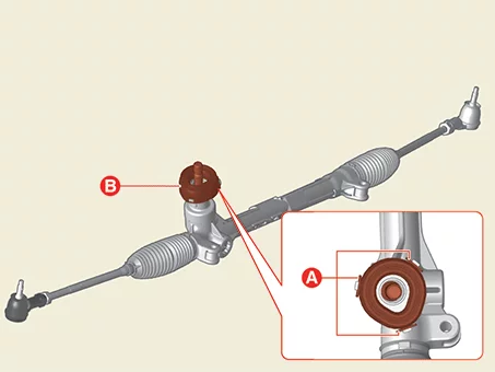
Release the mounting parts (A), and then remove the dust cap packing (B).
|
| 2.
|
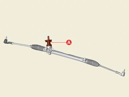
Remove the dust cap (A).
|
Bellows
| 1.
|
Replace with a new bellows.
|
When assembling the bellows, install it with the band and then assemble.
|
|
| 2.
|
Check the alignment.
(Refer to Suspension System - "Alignment")
|
Dust cap
| 1.
|
Replace with a new dust cap.
|
•
|
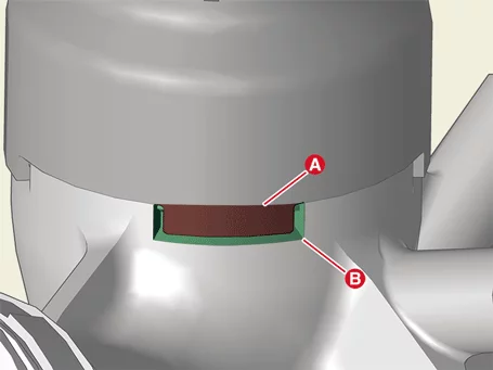
Ensure that the dust cap (A) fits into the steering gear box
grooves (B) when assembling.
|
|
•
|
Clean the pinion shaft before reassembling.
|
|
|
| 2.
|
Check the alignment.
(Refer to Suspension System - "Alignment")
|
Tie Rod End Removal and Installation
Tool Name / Number
|
Illustration
|
Description
|
Ball joint puller
09568 - 1S100
|
|
Used for removal of tie rod end and lower arm ball joint
|
| 1.
|
Remove the front wheel and tires.
(Refer to Suspension System - "Wheel")
|
| 2.
|
Separate the tie rod end ball joint from the front knuckle.
| (1)
|
Remove the split pin (A).
|
| (2)
|
Remove the lock nut (B).
|
Tightening torque :
34.3 - 44.1 N·m (3.5 - 4.5 kgf·m, 25.3 - 32.5 lb·ft)
|
|
•
|
Do not reuse the split pin.
|
|
•
|
Do not reuse the lock nut.
|
|
•
|
Be careful not to damage the ball joint boot.
|
|
•
|
Use a hand tool when removing or installing the
lock nut.
|
|
|
| (3)
|
Separate the tie rod end ball joint (A) using SST (09568 - 1S100).
|
|
| 3.
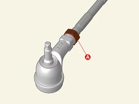
|
Loosen the tie rod end lock nut (A) until the tie rod end can rotate.
|
Tightening torque :
49.0 - 53.9 N·m (5.0 - 5.5 kgf·m, 36.2 - 39.8 lb·ft)
|
|
Measure the thread length (A) or mark the mounting position of the lock nut (B)
before removing.
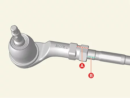
|
|
| 4.
|
Rotate the tie rod end (A) counterclockwise to remove.
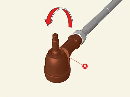
|
| 1.
|
Install in reverse order of removal.
|
When installing a single unit, install it to the specified torque.
|
|
| 2.
|
Replace the tie rod end with a new one.
|
| 3.
|
Check the alignment.
(Refer to Suspension System - "Alignment")
|
Other information:
Kia K4 (CL4) 2025-2026 Service Manual: Junction Crossing, Lane-Change Oncoming, Lane-Change Side, Evasive Steering Assist function:
These advanced assistance functions in the Kia K4 may experience abnormal operation or unexpected deactivation under certain circumstances, including:
The ambient temperature surrounding the front or rear-side radar sensors is outside of the safe operating range (too high or too low).
You have installed a trailer, aftermarket rack, or carrier in close proximity to the rear corner radar sensors, potentially blocking their field of view.
Kia K4 (CL4) 2025-2026 Service Manual: Trunk (for 4door)
CRITICAL LUGGAGE COMPARTMENT WARNING — EXHAUST FUME INTRUSION HAZARD:
Operating your vehicle while the trunk lid is unlatched or completely open creates a dangerous aerodynamic low-pressure zone at the rear of the cabin. This vacuum effect can actively draw toxic exhaust fumes, including lethal carbon monoxide gases, into the passenger compartment, leading to severe respiratory illness, neurological damage, loss of consciousness, or death for the occupants inside your Kia K4.