Contents:
Components and Components Location
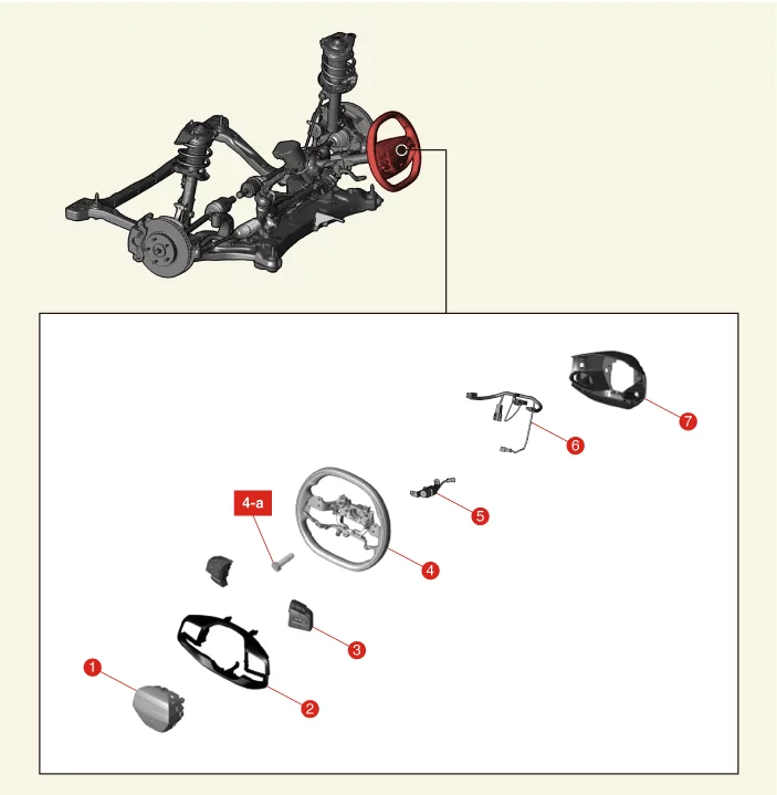
1. Driver Airbag (DAB)
2. Steering Wheel
Bezel
3. Steering Wheel Remote Control (SWRC) Switch
4. Steering Wheel Body
4-a. 39.3 -
49.0 N·m (4.0
- 5.0 kgf·m, 29.0 - 36.1 lb·ft)
|
5. Haptic Motor
6. Steering Wheel Extension
Wire
7. Steering Wheel Lower Cover
|
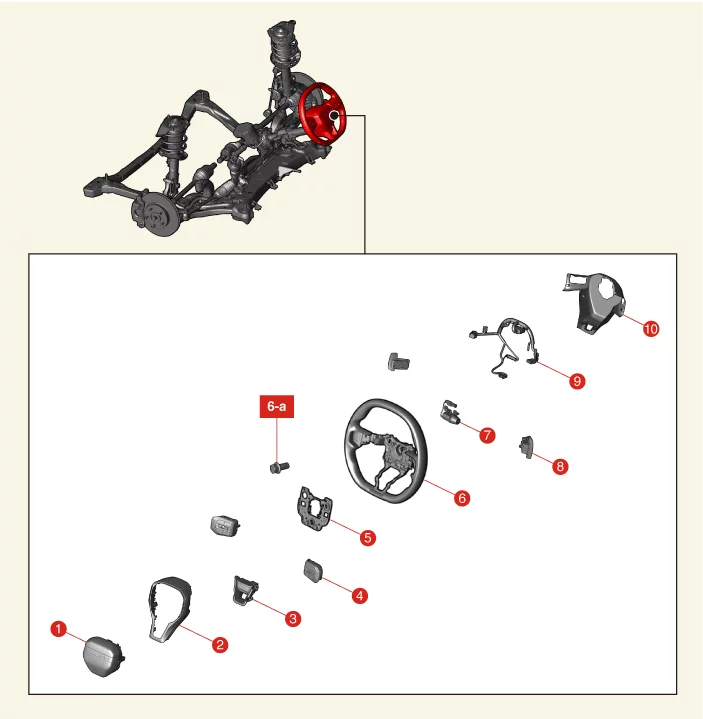
1. Driver Airbag (DAB)
2. Steering Wheel
Bezel
3. Drive Mode Switch
4. Steering Wheel Remote Control (SWRC) Switch
5. Horn Plate
|
6. Steering Wheel Body
6-a. 39.3 - 49.0 N·m
(4.0 -
5.0 kgf·m, 29.0 - 36.1 lb·ft)
7. Haptic Motor
8. Paddle Shifter Switch
9. Steering Wheel
Extension
Wire
10. Steering Wheel Lower Cover
|
Removal and Installation
| 1.
|
Align the steering wheel straight.
|
| 2.
|
Disconnect the battery negative ( - ) terminal.
|
| 3.
|
Remove the Driver Airbag (DAB).
(Refer to Restraint - "Driver Airbag (DAB)")
|
If the airbag is deployed, there may be a risk of injury, so always store the
detached airbag
module with the cover facing upwards.
|
|
| 4.
|
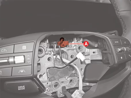
Disconnect the steering wheel connector (A).
|
| 5.
|
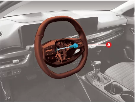
Remove the steering wheel (A) after removing the bolt.
|
Tightening torque :
39.2 - 49.0 N·m (4.0 - 5.0 kgf·m, 28.9 - 36.2 lb·ft)
|
|
•
|
Do not use a hammer when removing steering wheel, the steering
column may be damaged if
using a hammer.
|
|
•
|
Do not reuse the steering wheel bolt.
|
|
|
| 1.
|
Align the steering wheel straight.
|
| 2.
|
Disconnect the battery negative ( - ) terminal.
|
| 3.
|
Remove the Driver Airbag (DAB).
(Refer to Restraint - "Driver Airbag (DAB)")
|
If the airbag is deployed, there may be a risk of injury, so always store the
detached airbag
module with the cover facing upwards.
|
|
| 4.
|
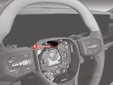
Disconnect the steering wheel connector (A).
|
| 5.
|
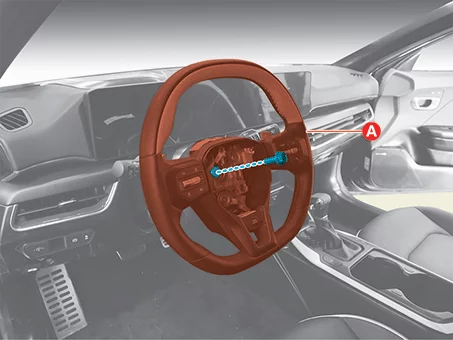
Remove the steering wheel (A) after removing the bolt.
|
Tightening torque :
39.2 - 49.0 N·m (4.0 - 5.0 kgf·m, 28.9 - 36.2 lb·ft)
|
|
•
|
Do not use a hammer when removing steering wheel, the steering
column may be damaged if
using a hammer.
|
|
•
|
Do not reuse the steering wheel bolt.
|
|
|
| 1.
|
Install in reverse order of removal.
|
•
|
Install to the specified torque.
|
|
•
|
Do not reuse the steering wheel bolt.
|
|
•
|
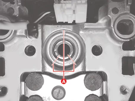
Mark the 3 points (A) at the steering wheel and column shaft
installation point.
|
|
|
Disassembly and Reassembly
Standard
| 1.
|
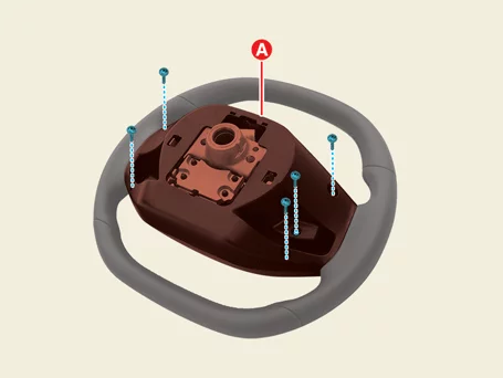
Remove the steering wheel lower cover (A) after removing the screws.
|
| 2.
|
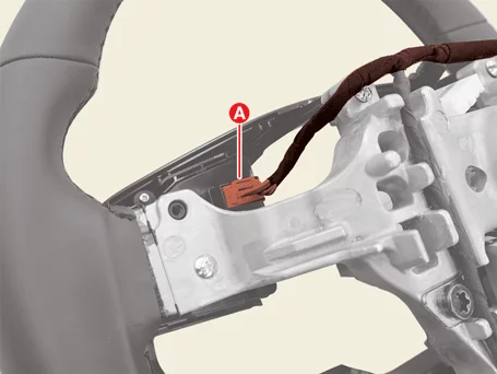
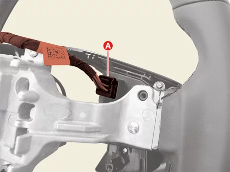
Disconnect the remote control switch connectors (A).
|
| 3.
|
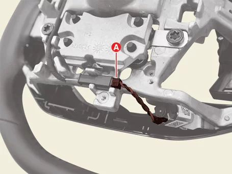
Disconnect the haptic motor connector (A).
|
| 4.
|
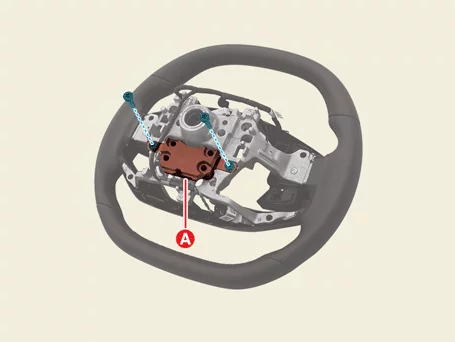
Remove the steering wheel dynamic damper (A) after removing the screws.
|
| 5.
|
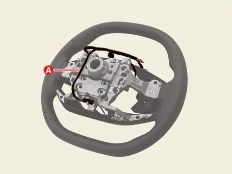
Remove the steering wheel extension wiring (A).
|
| 6.
|
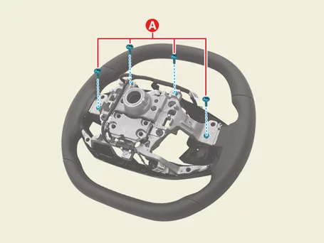
Remove the Steering Wheel Remote Control (SWRC) switch and bezel screws (A).
|
| 7.
|
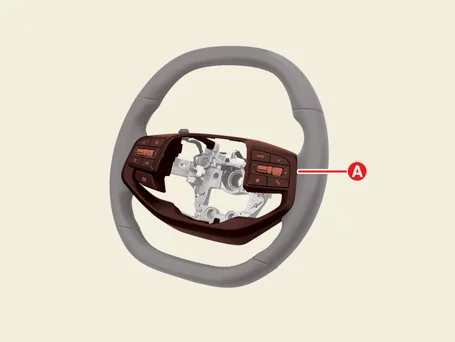
Remove the steering wheel remote control (SWRC) switch and bezel (A).
|
| 8.
|
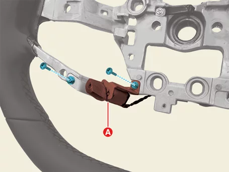
Remove the haptic motor (A) after removing the screws.
|
| 9.
|
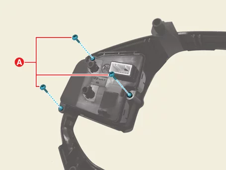
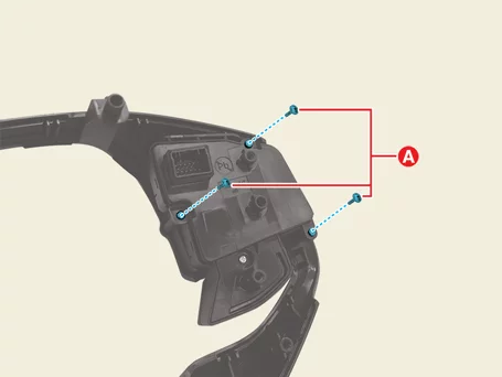
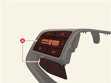
Remove the steering wheel remote control (SWRC) switch screws (A).
|
| 10.
|
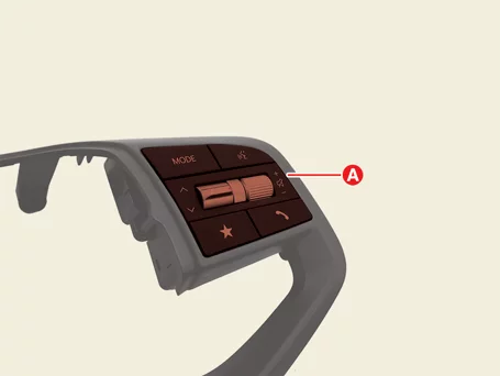
Remove the steering wheel remote control (SWRC) switches (A).
|
GT-line
| 1.
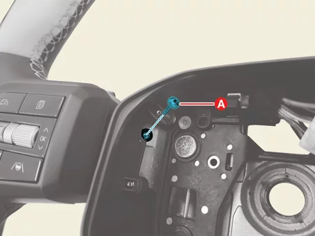
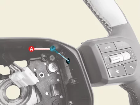
|
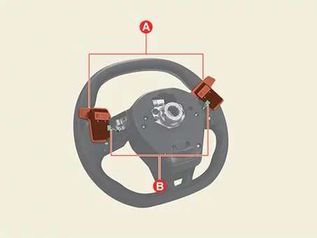
Remove the paddle shift switch mounting screws (A).
|
| 2.
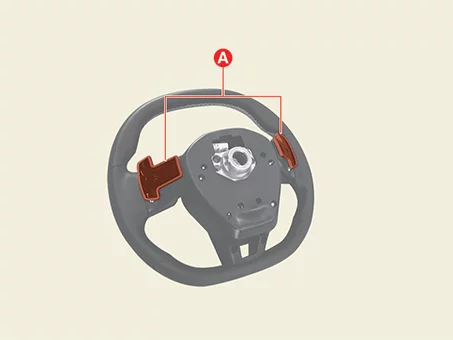
|
Separate the paddle shifter switches (A).
|
| 3.
|
Remove the paddle shift switches (A) after disconnecting the paddle shift connectors (B).
|
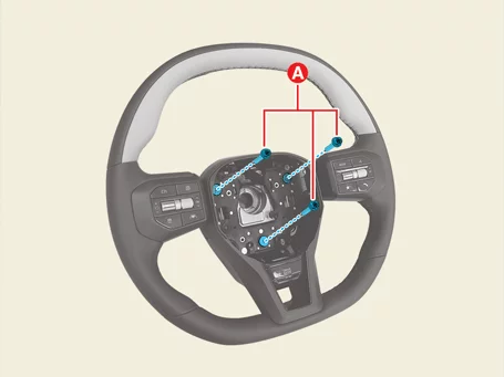
| 4.
|
Remove the horn plate screws (A).
|
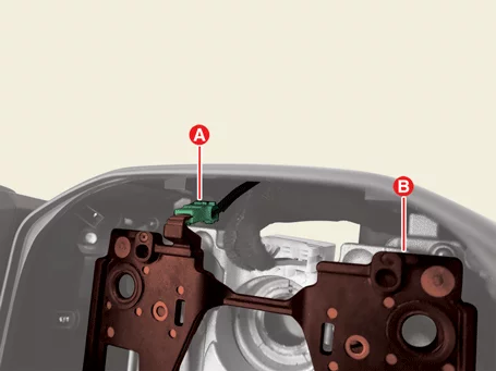
| 5.
|
Disconnect the horn connector (A), and then remove the horn plate (B).
|
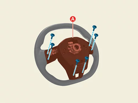
| 6.
|
Remove the steering wheel lower cover (A) after removing the screws.
|
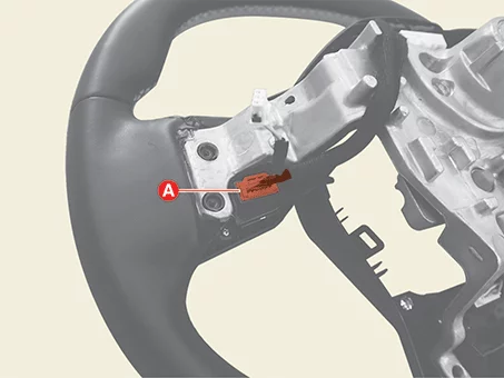
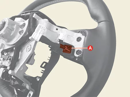
| 7.
|
Disconnect the remote control switch connectors (A).
|
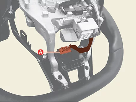
| 8.
|
Disconnect the drive mode switch connector (A).
|
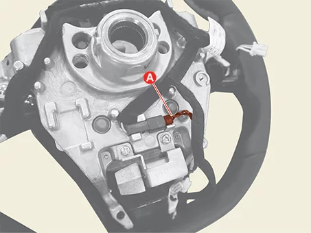
| 9.
|
Disconnect the haptic motor connector (A).
|
| 10.
|
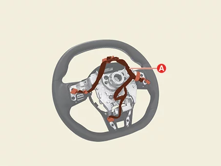
Remove the steering wheel extension wiring (A).
|
| 11.
|
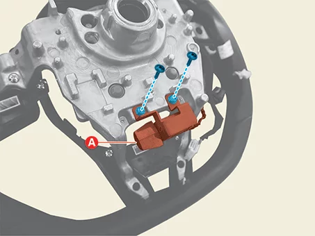
Remove the haptic motor (A) after removing the screws.
|
| 12.
|
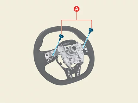
Remove the steering wheel remote control (SWRC) switch and bezel screws (A).
|
| 13.
|
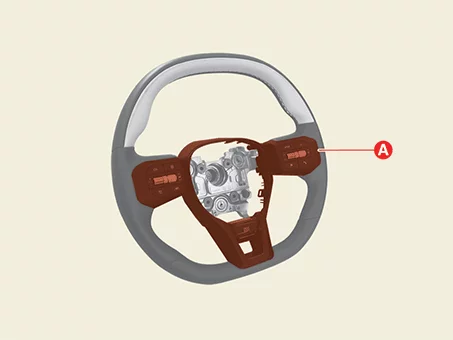
Remove the steering wheel remote control (SWRC) switch and bezel (A).
|
| 14.
|
Remove the steering wheel remote control (SWRC) switch screws (A).
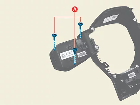
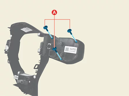
|
| 15.
|
Remove the steering wheel remote control (SWRC) switches (A).
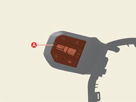
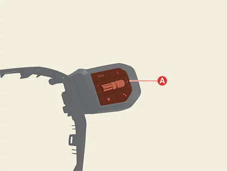
|
| 16.
|
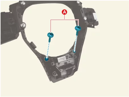
Remove the drive mode switch screws (A).
|
| 17.
|
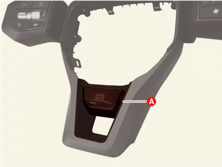
Remove the drive mode switch (A).
|
| 18.
|
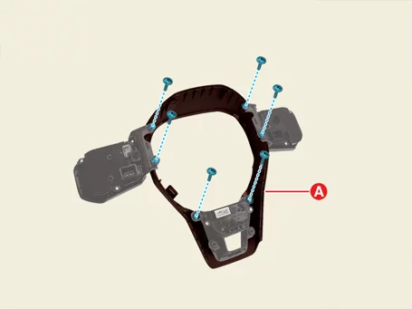
Remove the steering wheel bezel (A) after removing the screws.
|
| 1.
|
Reassemble in the reverse order of disassembly.
|
•
|
When assembling the steering wheel, be careful not to damage
the parts by tightening with
excessive torque.
|
|
•
|
When installing the steering wheel lower cover, an open circuit
or short circuit may
occur if the extension wire is not secured in place.
|
|
|
Heated Steering Wheel Components and Components Location
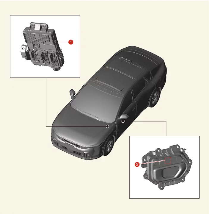
1. Heated Steering Wheel Control Unit
(Integrated
with Powernet Domain Controller)
2. Heated Steering Wheel Switch (Integrated with Front Door
Heated /
Ventilation Switch)
|
Heated Steering Wheel Replacement
| Heated Steering Wheel Control Unit |
|
The heated steering control unit is integrated with the powernet domain controller (PDC), so
replace the
PDC.
|
| 1.
|
Exchange the powernet domain controller.
(Refer to Body - "Junction Block")
|
|
The heated steering switch is integrated with the Integrated Memory Seat (IMS) Switch, so
replace the
Integrated Memory Seat (IMS) Switch.
|
| 1.
|
Exchange the integrated memory seat (IMS) switch.
(Refer to Body - "Integrated Memory Seat (IMS) Switch")
|
Paddle Shifter Removal and Installation
| 1.
|
Disconnect the battery negative ( - ) terminal.
|
| 2.
|
Remove the driver airbag module.
(Refer to Restraint - "Driver Airbag (DAB) Module")
|
If the airbag is deployed, there may be a risk of injury, so always store the
detached airbag
module with the cover facing upwards.
|
|
| 3.
|
Remove the paddle shift switch mounting screws (A).
[LH]
[RH]
|
| 4.
|
Separate the paddle shifter switch (A).
|
| 5.
|
Remove the paddle shift switches (A) after disconnecting the paddle shift connectors (B).
|
| 1.
|
Install in the reverse order of removal.
|
Other information:
Kia K4 (CL4) 2025-2026 Service Manual: Light switch settings
Setting
Result
Figure 1. Position lamp and taillight
Front position lamp, taillights, and license plate lamp are ON.
TIP
The Kia K4 must be in the ON position to turn on these headlights.
Kia K4 (CL4) 2025-2026 Service Manual: Engine compartment fuse replacement
For fuses located within the engine compartment fuse panel of your Kia K4, follow these maintenance steps:
Verify that the ENGINE START/STOP button and all vehicle systems are in the OFF position.
Open the engine compartment and remove the fuse panel cover by depressing the retaining tabs and lifting the cover upward.
Use the integrated fuse puller located inside the engine compartment fuse panel to extract the suspected fuse.