|
•
|
This video was created using 3D graphics to help understand the vehicle
maintenance manual.
|
|
•
|
There may be some differences from actual vehicles.
|
|
•
|
The location and repair procedures of the parts may vary depending on vehicle
model, model year,
region, and specifications.
|
|
•
|
Check the KDS Guide for detailed information on how to use the KDS.
|
|
•
|
Check the manual for detailed maintenance procedures.
|
|
•
|
Unauthorized reproduction, distribution, or sharing of this video is
prohibited.
|
|
Piston and Connecting Rod Inspection
Connecting Rod
(Click to play)

Video: Connecting Rod Inspection
Piston
(Click to play)
Video: Piston Inspection
Piston ring
(Click to play)
Video: Piston ring Inspection
Piston pin
(Click to play)
Video: Piston pin Inspection
The connecting rods.
| 1.
|
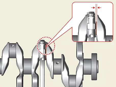
Inspect the side clearance of connecting rod.
Measure the side clearance of connecting rod big end using a feeler gauge.
|
•
|
If the side clearance is outside the limit value, replace the connecting rod.
|
|
•
|
If the side clearance is still out of the limit value even after replacing the
connecting rod,
replace the crankshaft.
|
|
Side clearance
Specified value : 0.1 - 0.25 mm (0.0039
- 0.0098)
|
|
| 2.
|
Check the connecting rod bearing oil clearance.
| (1)
|
Check the connecting rod and connecting rod bearing marks.
|
| (2)
|
Remove the connecting rod bearing cap bolts.
|
| (3)
|
Remove the connecting rod bearing cap and lower bearing.
|
| (4)
|
Clean the crankshaft pin journals and bearings.
|
| (5)
|
Place the plastic gauge axially.
|
| (6)
|
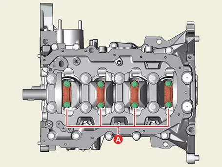
Reinstall the lower bearing and connecting rod cap and tighten the bolts to the
specified torque.
|
Tightening torque
Step 1 : 17.7 - 21.6 N·m
(1.8 - 2.2 kgf·m, 13.0 -
15.9 lb·ft)
Step 2 : 68 - 72°
|
|
•
|
Do not rotate the crankshaft.
|
|
•
|
Do not reuse connecting rod bearing cap bolts.
|
|
|
| (7)
|
Remove the connecting rod bearing cap and lower bearing.
|
| (8)
|
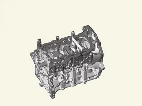
Measure the plastic gauge at its widest point.
|
Specified value : 0.037
- 0.055 mm (0.0014 -
0.0216 in.)
|
|
| (9)
|
If the measured value of the plastic gauge is out of the specified value,
replace it with a new
bearing with the same identification color and re-measure the oil gap. (Refer to
the connecting rod
bearing selection table)
|
Do not adjust the clearance by machining the bearing or cap.
|
|
| (10)
|
If the remeasured value is still out of the specified value, install the next
larger or smaller
bearing and then remeasure the oil clearance.
|
If the marks are indecipherable because of an accumulation of
dirt and dust, do not scrub
them with a wire brush or scraper. Clean them only with solvent
or detergent.
|
Classification Mark Position For
Connecting Rod
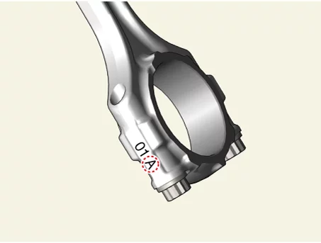
Classification table for connecting
rod
Classification Mark
|
Mark
|
Inside Diameter
|
A
|
0
|
45.000 - 45.006 mm (1.7717 - 1.7719 in.)
|
B
|
1
|
45.006 - 45.012 mm (1.7719 - 1.7721 in.)
|
C
|
2
|
45.012 - 45.018 mm (1.7721 - 1.7724 in.)
|
Classification mark position for
outer diameter of
crankshaft pin
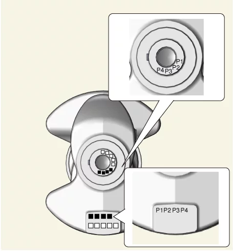
Identification Of Crankshaft Pin
Outside Diameter
Classification Mark
|
Mark
|
Pin journal diameter
|
â…
|
1
|
41.966 - 41.972 mm (1.6522 - 1.6524 in.)
|
â…¡
|
2
|
41.960 - 41.966 mm (1.6520 - 1.6522 in.)
|
â…¢
|
3
|
41.954 - 41.960 mm (1.6517 - 1.6520 in.)
|
Classification Color Position For
Connecting Rod
Bearing
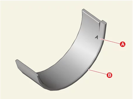
A : Mark
B : Color
Classification Table For Connecting
Rod Bearing
Classification Mark
|
Color
|
Connecting rod bearing
thickness
|
A
|
Blue
|
1.510 - 1.513 mm (0.05945 - 0.05957 in.)
|
B
|
Black
|
1.507 - 1.510 mm (0.05933 - 0.05945 in.)
|
C
|
No color
|
1.504 - 1.507 mm (0.05921 - 0.5933 in.)
|
D
|
Green
|
1.501 - 1.504 mm (0.05909 - 0.05921 in.)
|
E
|
Red
|
1.498 - 1.501 mm (0.05898 - 0.05909 in.)
|
|
| (11)
|
Select the proper connecting rod bearing using the below bearing selection
table.
Selection Table For Connecting Rod
Bearing
|
Connecting Rod
Identification Mark
|
A
|
B
|
C
|
Crank
shaft
pin journal
classification mark
|
1
|
E
(Red)
|
D
(Green)
|
C
(No Color)
|
2
|
D
(Green)
|
C
(No Color)
|
B
(Black)
|
3
|
C
(No Color)
|
B
(Black)
|
A
(Blue)
|
|
|
| 3.
|
Check the connecting rods.
| (1)
|
When installing a new connecting rod, make sure that the bearing retaining
notch on the rod and
cap are installed in the same direction.
|
| (2)
|
If even one end of the connecting rod is damaged, replace the connecting rod.
Also, replace it
when the inner surface of the small end of the connecting rod is worn out or the
inner surface is
too rough.
|
| (3)
|
Measure the bending and torsion of the rod using a connecting rod aligner, and
if the measured
value is close to the limit, correct the rod using a press. If the bending and
torsion are
excessive, replace the connecting rod.
|
Allowable bend of connecting
rod : 0.05 mm 0.05
(0.0020 in.) / 100 mm (3.9370 in.)
Allowable twist of connecting
rod : 0.1 mm (0.0039
in.) / 100 mm (3.9370 in.)
|
|
When the connecting rods are installed without bearings, there
should be no difference on
side surface.
|
|
|
Piston
| 1.
|
Clean the piston.
| (1)
|
Using a gasket scraper, remove the carbon from the piston top.
|
| (2)
|
Using a groove cleaning tool or broken ring, clean the piston ring grooves.
|
| (3)
|
Using solvent and a brush, thoroughly clean the piston.
|
|
Do not use the wire brush.
|
|
| 2.
|
Check the clearance by calculating the difference between the cylinder bore inner diameter and
the piston
outer diameter.
|
Piston to cylinder clearance : 0.035 -
0.055 mm (0.001378
- 0.002165 in.)
|
| (1)
|
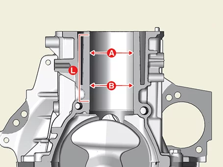
Using a cylinder bore gauge, measure the inner diameter points A and B of the
cylinder bore in
the axial and vertical directions.
|
Cylinder bore inner diameter
: 75.60 - 75.63 mm
(2.9764 - 2.9776 in.)
|
|
L : The straight
distance between the piston TDC
NO.1 ring and BDC oil ring
A : 1/4 point of L.
B : 3/4 point of L.
|
|
| (2)
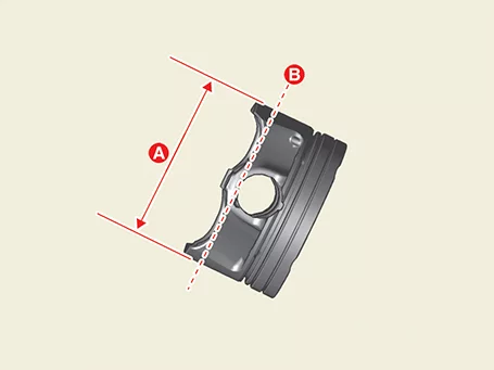
|
The outer diameter of the piston is based (A) on the value measured 13.000 mm
(0.5118 in.) above
the bottom of the piston.
|
Specified value :
75.555 - 75.585 mm (2.9746 -
2.9758 in.)
|
|
|
| 3.
|
Select a suitable piston according to the size of the cylinder inner diameter.
| (1)
|
Check the size mark on the side of the cylinder block.
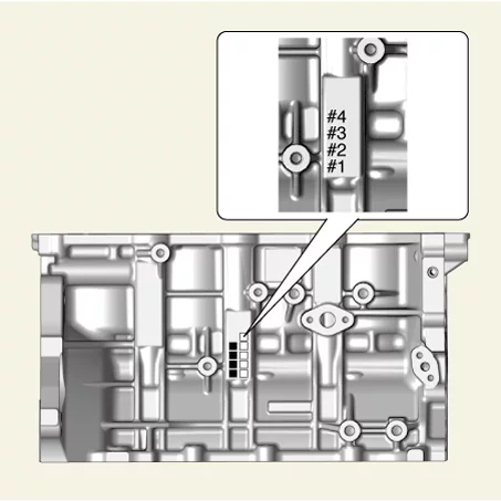
Cylinder Bore Size Classification
Table
Class
|
Mark
|
Cylinder Bore Inner
Diameter
|
a
|
A
|
75.60 - 75.61 mm (2.9764 - 2.9768 in.)
|
b
|
B
|
75.61 - 75.62 mm (2.9768 - 2.9772 in.)
|
c
|
C
|
75.62 - 75.63 mm (2.9772 - 2.9776 in.)
|
|
| (2)
|
Check the piston outer diameter size indication on the upper surface of the
piston.
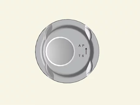
A : Classification mark (A, B, C)
T : Type/Engine mark (T-GDI)
6: Cylinder number classification mark (1.6 L)
P: Specification
Piston Outer diameter Size
Classification Table
Mark
|
Piston outer diameter
|
A
|
75.555 - 75.565 mm (2.9746 - 2.9750 in.)
|
B
|
75.565 - 75.575 mm (2.9750 - 2.9754 in.)
|
C
|
75.575 - 75.585 mm (2.9754 - 2.9758 in.)
|
|
|
Piston ring
| 1.
|
Inspect the piston ring side clearance.
| (1)
|
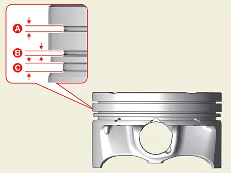
Measure the clearance between the piston ring groove and the piston ring using
a feeler gauge.
|
Piston ring groove width
dimensions
Piston ring (NO.1) (A) :
1.23 - 1.25 mm (0.0484 -
0.04921 in.)
Piston ring (No. 2) (B) :
1.03 - 1.05 mm (0.0405
- 0.0413 in.)
Oil ring(C) : 2.030 -
2.045 mm (0.0799 - 0.08051
in.)
|
|
| (2)
|
Measure the piston ring width using a micrometer.
|
Piston ring width
dimensions
Piston ring (No. 1) (A)
: 1.17 - 1.19 mm (0.0461 -
0.0468 in.)
Piston ring (No. 2) (B)
: 0.97 - 0.99 mm (0.0382 -
0.0390 in.)
Oil ring (C) : 1.92 -
1.95 mm (0.0756 - 0.0768
in.)
|
|
| (3)
|
Measure the side clearance between the piston and piston ring using a feeler
gauge.
|
Piston ring side
clearance
Piston ring (No.1) (A) :
0.04 - 0.08 mm (0.00157 -
0.00314 in.)
Piston ring (No.2) (B) :
0.04 - 0.08 mm (0.00157 -
0.00314 in.)
Oil ring (C) : 0.080 -
0.125 mm (0.00315 - 0.00492
in.)
|
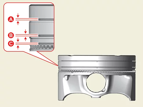
If the clearance is over than limit value, replace the piston.
|
|
| 2.
|
Inspect piston ring end gap.
| (1)
|
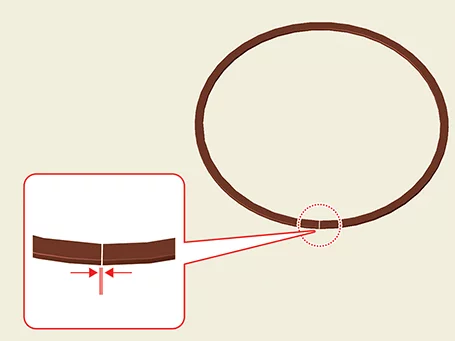
Insert the piston ring into the cylinder to measure the end gap of the piston
ring.
|
| (2)
|
At this time, gently push the ring with the piston so that the ring is
positioned at the correct
angle with the cylinder wall.
|
| (3)
|
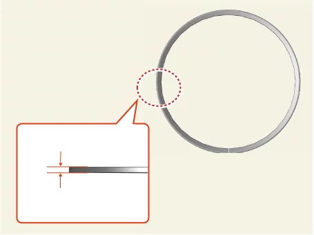
Measure the end gap using a filler gauge and replace the piston ring if the
measured value
exceeded the limit value.
|
piston ring end gap
Specifications
No. 1 ring : 0.14 - 0.19
mm (0.0055 - 0.0074 in.)
No. 2 ring : 0.20 - 0.30
mm (0.0078 - 0.011 in.)
Oil ring : 0.10 - 0.40
mm (0.0039 - 0.0157 in.)
|
|
|
Piston pin
| Clearance inspection between the piston pin and piston.
|
| 1.
|
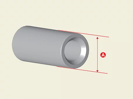
Measure the piston pin outer diameter (A).
|
Specified value : 18.997 - 19.000 mm
(0.7479 - 0.7480 in.)
|
|
| 2.
|
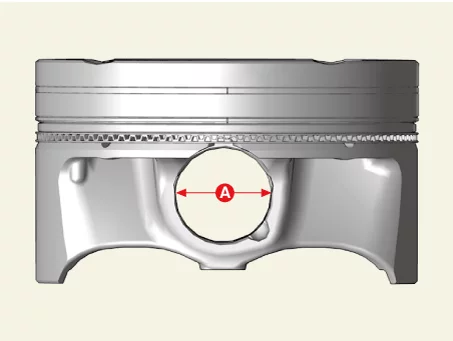
Measure the piston pin hole inner diameter (A).
|
Specified value : 19.004 - 19.009 mm
(0.7481 - 0.7483 in.)
|
|
| 3.
|
Calculate the side clearance using the piston pin outer diameter and piston pin hole inner
diameter.
|
Expression : (Piston pin hole inner
diameter) - (Piston
pin outer diameter) = (Side spacing)
Specified value : 0.004 - 0.012 mm
(0.000157 - 0.000472
in.)
|
|
| Clearance inspection between the piston pin and connecting
rod.
|
| 1.
|
Measure the diameter (A) of the piston pin.
|
Specified value : 18.997 - 19.000 mm
(0.74791 - 0.74803
in.)
|
|
| 2.
|
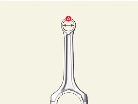
Measure the connecting rod small end inner diameter (A).
|
Specified value : 19.005 - 19.011 mm
(0.74823 - 0.74846
in.)
|
|
| 3.
|
Calculate the clearance using the piston pin outer diameter and connecting rod small end inner
diameter.
|
Expression : (Connecting rod small end
inner diameter) -
(Piston pin outer diameter) = (Side spacing)
Specified value : 0.005 - 0.014 mm
(0.000196 - 0.000551
in.)
|
|
Other information:
Kia K4 (CL4) 2025-2026 Service Manual: Tightening Torque
Tightening Torque
Cooling System
Cooling Fan
Item
N·m
kgf·m
lb·ft
lb·in
Degassing hose clip bolt
3.
Kia K4 (CL4) 2025-2026 Service Manual: Storage compartments
The Kia K4 interior is designed with several convenient storage compartments to organize small items for both the driver and passengers:
For your security, it is highly recommended not to store high-value items in any vehicle storage compartments to avoid potential theft.
Always ensure that compartment lids are fully closed while the Kia K4 is in motion.