Contents:
Components and Components Location
| Components and Components Location |
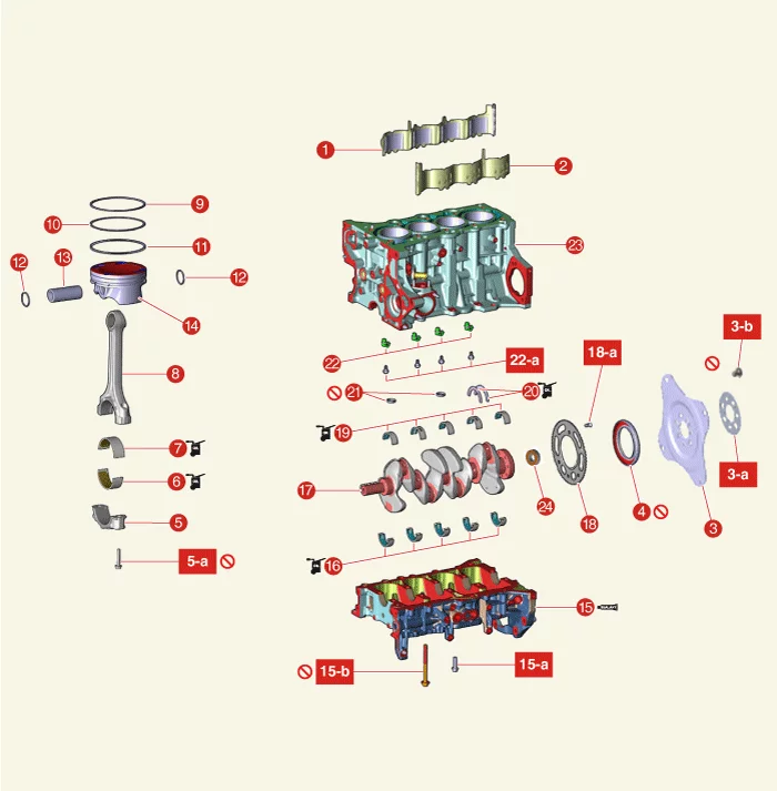
1. Water Jacket
Insert
[Exhaust]
2. Water Jacket Insert [Intake]
3. Drive Plate
3-a Drive Plate Adapter
3-b.
71.6 - 75.5
N·m (7.3 - 7.7 kgf·m, 52.8 - 55.7 lb·ft)
4. Rear Oil Seal
5. Connecting Rod Bearing
Cap
5-a. Step 1 :
17.7 - 21.6 N·m (1.8 - 2.2 kgf·m, 13.0 - 15.9 lb·ft)
5-a. Step 2 : 68 - 72°
6. Connecting Rod
Lower
Bearing
7. Connecting Rod Upper Bearing
8. Connecting Rod
9. Piston Ring (No.1)
10.
Piston Ring
(No.2)
11. Oil Ring
12. Snap Ring
13. Piston Pin
|
14.
Piston
15. Lower
Crankcase
15-a. 18.6 - 23.5 N·m (1.9 - 2.4 kgf·m, 13.7 - 17.4 lb·ft)
15-b. Step 1 : 27.5 -
31.4 N·m (2.8
- 3.2 kgf·m, 20.3 - 23.1 lb·ft)
15-b. Step 2 : 118 - 122°
16. Crankshaft Lower Bearing
17.
Crankshaft
18. Crankshaft Position Sensor Wheel
18-a. 12.7 - 13.7 N·m (1.3 - 1.4 kgf·m, 9.4 -
10.1
lb·ft)
19. Crankshaft Upper Bearing
20. Thrust Bearing
21. O-Ring
22. Piston Cooling Oil
Jet
22-a. 8.8 - 12.7 N·m (0.9 - 1.3 kgf·m, 6.5 - 9.4 lb·ft)
23. Cylinder Block
24. Pilot
Bearing
|
Water Jacket Insert Removal and Installation
| 1.
|
Remove the cylinder head.
(Refer to Cylinder Head Assembly - "Cylinder Head")
|
| 2.
|
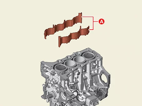
Remove the water jacket insert (A).
|
When removing the water jacket insert, be careful not to damage the top
surfaces of the cylinder
block.
|
|
| 1.
|
Install in reverse order of removal.
|
•
|
Do not reuse the water jacket insert.
|
|
•
|
Refit the top of the water jacket insert so that it is located
below the top of the
cylinder block.
|
|
•
|
When installing the water jacket insert, check the LH, RH
classification and installation
directions.
|
|
•
|
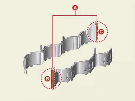
When fitting a new water jacket insert, check the lip seal (A)
and the cylinder block
mounting surface before refitting.
B : Intake
C : Exhaust
|
|
•
|
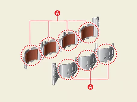
Do not press the sus spring (A) when installing a new water
jacket insert.
|
|
|
Drive Plate Removal and Installation
| 1.
|
Remove the automatic transaxle.
(Refer to Automatic Transaxle System - "Automatic
Transaxle")
|
| 2.
|
Remove the drive plate adapter (A) and drive plate (B).
|
Tightening torque :
71.6 - 75.5 N·m (7.3 - 7.7 kgf·m, 52.8 - 55.7 lb·ft)
|
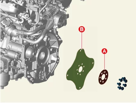
|
Do not reuse drive plate bolt.
|
|
| 1.
|
Install in reverse order of removal.
|
Install to the specified torque.
|
|
Rear Oil Seal Replacement
Tool Name / Number
|
Illustration
|
Description
|
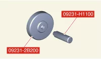
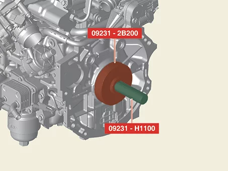
Crankshaft rear oil seal installer
09231 - H1100
09231 - 2B200
|
|
Used for installing crankshaft rear oil seal
|
| 1.
|
Remove the drive plate.
(Refer to Cylinder Block - "Drive plate")
|
| 2.
|
Remove the rear oil seal (A).
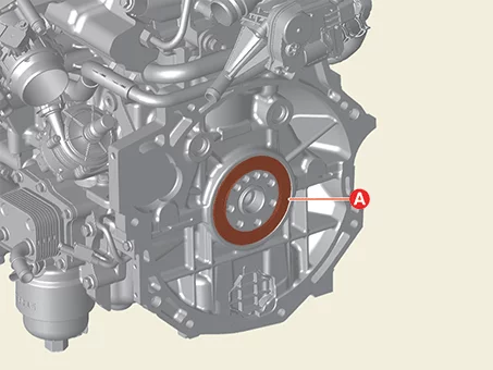
|
| 3.
|
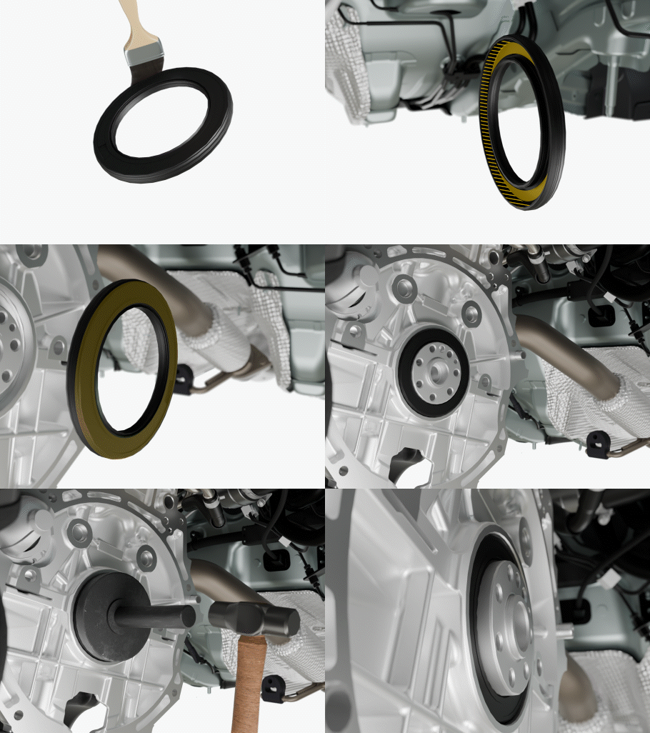
Install the oil seal with new one.
| (1)
|
Apply engine oil to the outer peripheral surface of the new rear oil seal.
|
| (2)
|
Using the SST (09231 - H1100, 09231 - 2B200), install the new rear oil seal.
|
Do not reuse the rear oil seal.
|
|
|
| 4.
|
Install in reverse order of removal.
|
Piston and Connecting Rod Disassembly
|
•
|
This video was created using 3D graphics to help understand the vehicle
maintenance manual.
|
|
•
|
There may be some differences from actual vehicles.
|
|
•
|
The location and repair procedures of the parts may vary depending on vehicle
model, model year,
region, and specifications.
|
|
•
|
Check the KDS Guide for detailed information on how to use the KDS.
|
|
•
|
Check the manual for detailed maintenance procedures.
|
|
•
|
Unauthorized reproduction, distribution, or sharing of this video is
prohibited.
|
|
Piston and Connecting Rod Removal and Disassembly
(Click to play)

Video: Piston and Connecting Rod Removal and
Disassembly
|
•
|
Use a fender cover to protect the painted surface.
|
|
•
|
Wait for the engine to cool to room temperature before disassembling to prevent
damage to the
cylinder head.
|
|
•
|
When handling a metal gasket, take care not to fold the gasket or damage the
contact surface of
the gasket.
|
|
•
|
Be careful not to damage the connector when disconnecting.
|
|
|
•
|
Mark all wiring and hoses to prevent incorrect connections.
|
|
•
|
Turn the crankshaft to position the piston of cylinder 1 at compression top
dead center.
|
|
| 1.
|
Remove the engine and transaxle assembly.
(Refer to Engine and Transaxle Assembly - "Engine and Transaxle
Assembly")
|
| 2.
|
Remove the automatic transaxle.
(Refer to Automatic Transaxle System - "Automatic
Transaxle")
|
| 3.
|
Remove the rear oil seal.
(Refer to Cylinder Block - "Rear Oil Seal")
|
| 4.
|
Install the engine on the engine stand for disassembly.
|
| 5.
|
Remove the intake manifold.
(Refer to Intake and Exhaust System - "Intake Manifold")
|
| 6.
|
Remove the turbo manifold.
(Refer to Intake and Exhaust System - "Turbo Manifold")
|
| 7.
|
Remove the cylinder head cover.
(Refer to Cylinder Head Assembly - "Cylinder Head
Cover")
|
| 8.
|
Remove the oil pan.
(Refer to Lubrication - "Oil Pan")
|
| 9.
|
Remove the timing chain.
(Refer to Timing System - "Timing Chain Cover")
|
| 10.
|
Remove the Integrated Thermal Management Module (ITM).
(Refer to Cooling System - "Integrated Thermal Management
Module
(ITM)")
|
| 11.
|
Remove the cylinder head.
(Refer to Cylinder Head Assembly - "Cylinder Head")
|
| 12.
|
Remove the oil pump.
(Refer to Lubrication System - "Oil Pump")
|
| 13.
|
Remove the piston and connecting rod assembly.
| (1)
|
Remove the carbon deposits on the top of piston.
|
| (2)
|
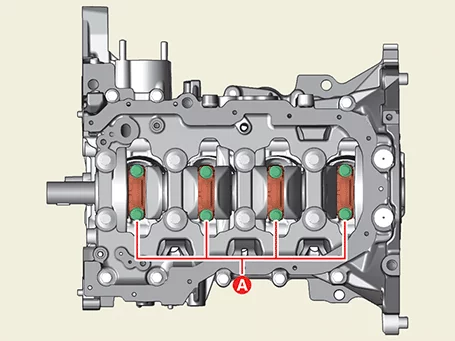
Remove the connecting rod bearing caps (A) after removing the bolts.
|
Tightening torque
Step 1 : 17.7 - 21.6 N·m
(1.8 - 2.2 kgf·m, 13.0 -
15.9 lb·ft)
Step 2 : 68 - 72°
|
|
Mark the connecting rod, and caps to be able to reassemble in
the original position and
direction.
|
|
| (3)
|
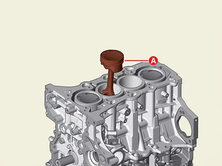
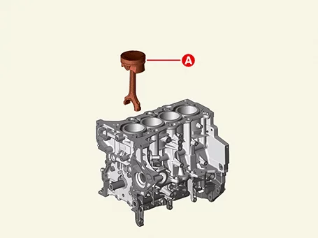
Push the piston and connecting rod assembly (A) with upper bearing through the
top of the
cylinder block.
|
|
•
|
Keep the connecting rod and cap with their bearings assembled
together.
|
|
•
|
Arrange the piston and connecting rod assemblies in the correct
order.
|
|
•
|
Mark the cylinder No. so that the piston and connecting rod
assembly removed from each
cylinder can be installed to original positon.
|
|
|
| 14.
|
Check the clearance between the piston and the piston pin.
If you feel a gap with the piston pin, move the piston back and forth and exchange the piston
and piston
pin.
|
| 15.
|
Remove the piston ring.
| (1)
|
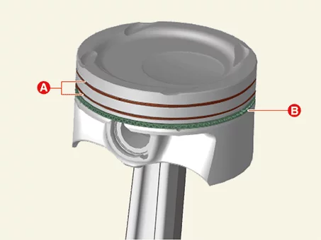
Remove the piston ring (A) and oil ring (B).
|
|
| 16.
|
Remove the piston and connecting rod.
| (1)
|
Remove the snap ring (A).
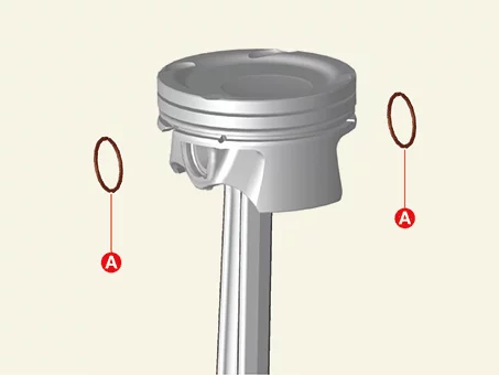
|
| (2)
|
Remove the piston pin (A) from the piston.
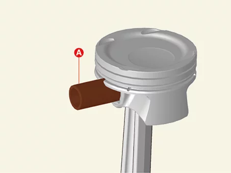
|
| (3)
|
Remove the piston (A) and the connecting rod (B).
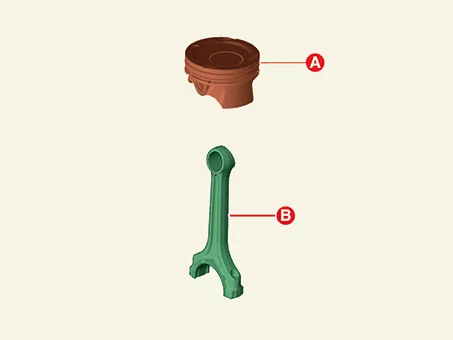
|
|
Piston and Connecting Rod Reassembly
|
•
|
This video was created using 3D graphics to help understand the vehicle
maintenance manual.
|
|
•
|
There may be some differences from actual vehicles.
|
|
•
|
The location and repair procedures of the parts may vary depending on vehicle
model, model year,
region, and specifications.
|
|
•
|
Check the KDS Guide for detailed information on how to use the KDS.
|
|
•
|
Check the manual for detailed maintenance procedures.
|
|
•
|
Unauthorized reproduction, distribution, or sharing of this video is
prohibited.
|
|
Piston and Connecting Rod Reassembly and Installation
(Click to play)
Video: Piston and Connecting Rod Reassembly and
Installation
|
•
|
Thoroughly clean all parts to be assembled.
|
|
•
|
Before installing the parts, apply fresh engine oil to all sliding and rotating
surfaces.
|
|
| 1.
|
Assemble the piston and the connecting rod.
| (1)
|
Install the snap ring (A) on one side of the piston pin hole.
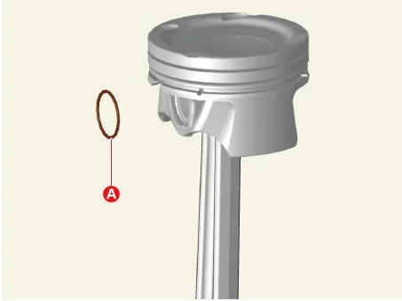
|
| (2)
|
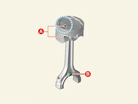
Align the front mark (A) on the piston with the front mark (B) on the
connecting rod.
|
| (3)
|
Insert the piston pin (A) into the piston pinhole and the hole at the small end
of the connecting
rod.
|
| (4)
|
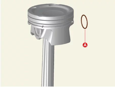
Install the snap ring (A) in the remaining holes of the piston pin.
|
•
|
Before assembling the piston pin, apply a
sufficient amount of engine to the
outer surface of piston, inner surface of piston
hole and connecting small end bore.
|
|
•
|
When inserting, be careful not to damage or
scratch the connecting rod small end
hole, piston pin and piston pin hole.
|
|
•
|
Set the snap ring so that it contacts securely
with the whole groove of the
piston pin hole.
|
|
•
|
Do not reuse snap ring.
|
|
•
|
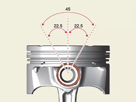
The snap ring cutout is installed so that it is
positioned 45° upwards.
|
|
|
|
| 2.
|
Install the piston ring.
| (1)
|
Install the oil ring expander and the two side rails by hand.
|
| (2)
|
Install the 2 compression rings using the piston ring expander with the
engraving marks on the
piston facing upwards.
|
| (3)
|
Make sure the end of each piston ring is seated as shown below.
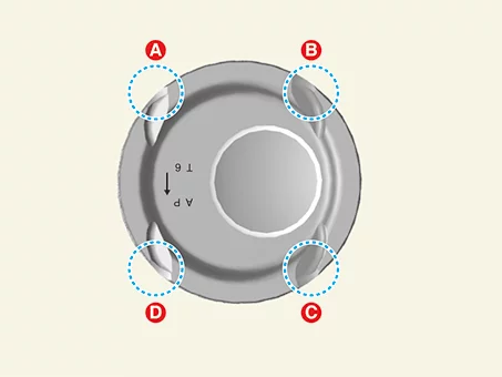
A : Lower side ring
B : Piston ring (NO.1)
C : Upper side rail
D : Piston ring (NO.2)
|
|
| 3.
|
Install the connecting rod bearings.
| (1)
|
Make sure that the grooves of the connecting rod and bearing cap are aligned
with the protrusion
of the bearing.
|
| (2)
|
Install the bearing (A) on the connecting rod and the connecting rod bearing
cap.
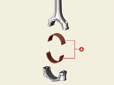
|
|
| 4.
|
Install the piston connecting rod assembly.
|
•
|
Before installing the piston, apply a coat of engine oil to the
ring grooves and cylinder
bores.
|
|
•
|
Make sure the front mark (A) on the piston and the front mark
(B) on the connecting rod
face the timing chain.
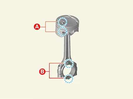
|
|
| (1)
|
Install the ring compressor, check that the rings are securely in place, and
then position the
piston in the cylinder, and tap it in using the wooden handle of a hammer.
|
| (2)
|
When the piston ring parts enter the cylinder, stop inserting and recheck the
alignment of the
journal and connecting rod.
|
Insert the piston while pressing down the piston ring
compressor to prevent the piston
ring expansion before piston ring is inserted into the cylinder.
|
|
| (3)
|
Install the connecting rod caps (A) and then tighten the bolts to the specified
torque.
|
Tightening torque
Step 1 : 17.7 - 21.6 N·m
(1.8 - 2.2 kgf·m, 13.0 -
15.9 lb·ft)
Step 2 : 68 - 72°
|
|
Do not reuse connecting rod bearing cap bolts.
|
|
|
| 5.
|
Install in reverse order of removal.
|
Install the piston and connecting rod to the specified torque.
|
|
Crankshaft Disassembly
|
•
|
This video was created using 3D graphics to help understand the vehicle
maintenance manual.
|
|
•
|
There may be some differences from actual vehicles.
|
|
•
|
The location and repair procedures of the parts may vary depending on vehicle
model, model year,
region, and specifications.
|
|
•
|
Check the KDS Guide for detailed information on how to use the KDS.
|
|
•
|
Check the manual for detailed maintenance procedures.
|
|
•
|
Unauthorized reproduction, distribution, or sharing of this video is
prohibited.
|
|
Crankshaft Removal
(Click to play)
Video: Crankshaft Removal
|
•
|
Use a fender cover to protect the painted surface.
|
|
•
|
Wait for the engine to cool to room temperature before disassembling to prevent
damage to the
cylinder head.
|
|
•
|
When handling a metal gasket, take care not to fold the gasket or damage the
contact surface of
the gasket.
|
|
•
|
Be careful not to damage the connector when disconnecting.
|
|
|
•
|
Mark all wiring and hoses to prevent incorrect connections.
|
|
•
|
Rotate the crankshaft to place the no.1 cylinder piston at the compress TDC.
|
|
| 1.
|
Remove the engine and transaxle assembly.
(Refer to Engine and Transaxle Assembly - "Engine and Transaxle
Assembly")
|
| 2.
|
Remove the automatic transaxle.
(Refer to Automatic Transaxle System - "Automatic
Transaxle")
|
| 3.
|
Remove the drive plate.
(Refer to Cylinder Block - "Drive plate")
|
| 4.
|
Remove the rear oil seal.
(Refer to Cylinder Block - "Rear Oil Seal")
|
| 5.
|
Install the engine assembly on the stand.
|
| 6.
|
Remove the intake manifold.
(Refer to Intake and Exhaust System - "Intake Manifold")
|
| 7.
|
Remove the turbo manifold.
(Refer to Intake and Exhaust System - "Turbo Manifold")
|
| 8.
|
Remove the cylinder head cover.
(Refer to Cylinder Head Assembly - "Cylinder Head
Cover")
|
| 9.
|
Remove the oil pan.
(Refer to Lubrication - "Oil Pan")
|
| 10.
|
Remove the timing chain.
(Refer to Timing System - "Timing Chain Cover")
|
| 11.
|
Remove the Integrated Thermal Management Module (ITM).
(Refer to Cooling System - "Integrated Thermal Management
Module
(ITM)")
|
| 12.
|
Remove the cylinder head.
(Refer to Cylinder Head Assembly - "Cylinder Head")
|
| 13.
|
Remove the oil pump.
(Refer to Lubrication System - "Oil Pump")
|
| 14.
|
Remove the oil filter & oil cooler.
(Refer to Lubrication System - "Oil filter & oil
cooler")
|
| 15.
|
Remove the piston and connecting rod.
(Refer to Cylinder Block - "Piston and Connecting Rod")
|
| 16.
|
Remove the rear cap (A).
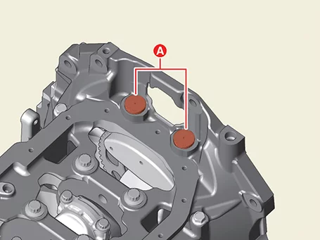
|
| 17.
|
Remove the lower crankcase.
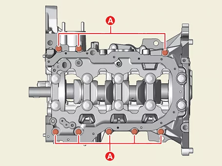
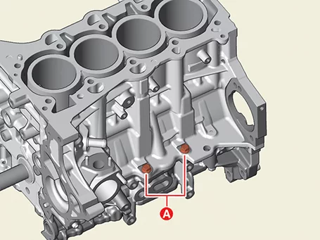
| (1)
|
Remove the lower crankcase bolts (A).
|
Tightening torque :
18.6 - 23.5 N·m (1.9 - 2.4 kgf·m, 13.7 - 17.4 lb·ft)
|
|
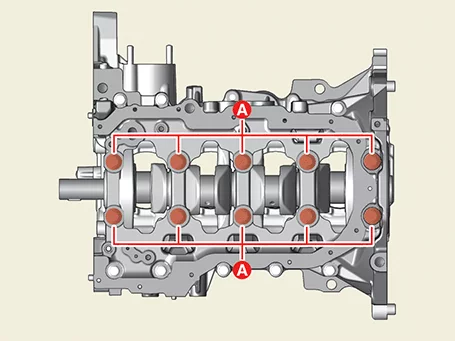
| (2)
|
Remove the crankshaft main bearing cap bolts (A).
|
Tightening torque
Step 1 :
27.5 - 31.4 N·m (2.8 - 3.2 kgf·m, 20.3 - 23.1 lb·ft)
Step 2 : 118 - 122°
|
|
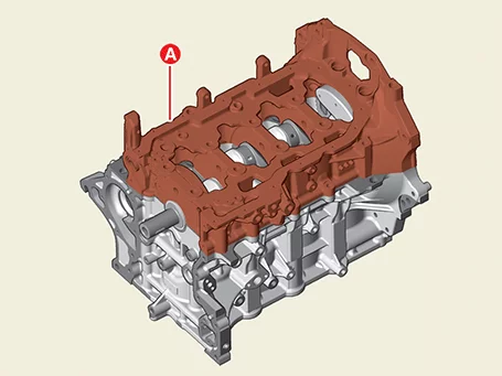
| (3)
|
R emove the crankcase (A).
|
|
| 18.
|
Lift the crankshaft (A) off the block.
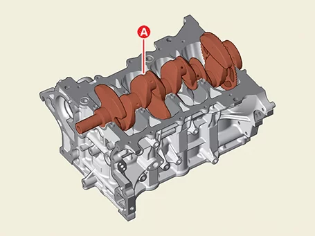
|
Be careful not to damage the journal.
|
|
| 19.
|
Remove the crankshaft position sensor wheel (A) after removing the bolts.
|
Specified torque :
12.7 - 13.7 N·m (1.3 - 1.4 kgf·m, 9.4 - 10.1 lb·ft)
|
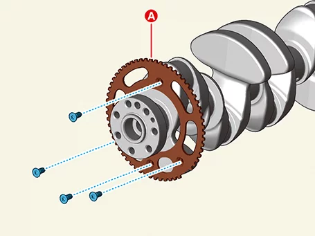
|
| 20.
|
Remove the main bearing.
| (1)
|
Remove the thrust bearing (A).
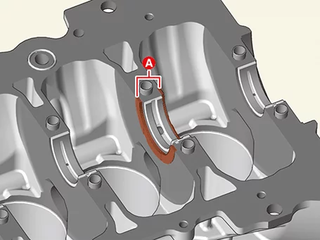
|
| (2)
|
Remove the upper bearing (A).
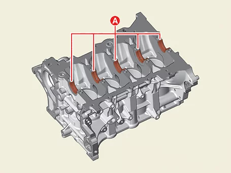
|
| (3)
|
Remove the lower bearing (A).
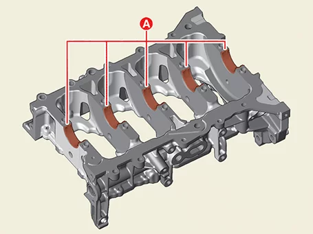
|
Align the main bearing and thrust bearing in order.
|
|
|
| 21.
|
Remove the cylinder block O-rings (A).
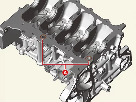
|
Do not reuse cylinder block O-ring (A)
|
|
Crankshaft Reassembly
|
•
|
This video was created using 3D graphics to help understand the vehicle
maintenance manual.
|
|
•
|
There may be some differences from actual vehicles.
|
|
•
|
The location and repair procedures of the parts may vary depending on vehicle
model, model year,
region, and specifications.
|
|
•
|
Check the KDS Guide for detailed information on how to use the KDS.
|
|
•
|
Check the manual for detailed maintenance procedures.
|
|
•
|
Unauthorized reproduction, distribution, or sharing of this video is
prohibited.
|
|
Crankshaft Installation
(Click to play)
Video: Crankshaft Installation
|
•
|
Thoroughly clean all parts to be assembled.
|
|
•
|
Apply new engine oil on the rotating surface before assembling parts.
|
|
•
|
Do not reuse gaskets, o-rings and oil rings.
|
|
| 1.
|
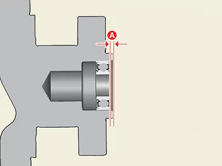
When replacing the crankshaft or short engine, check whether the pilot bearing (A) is
installed, and if
not, install the pilot bearing (A).
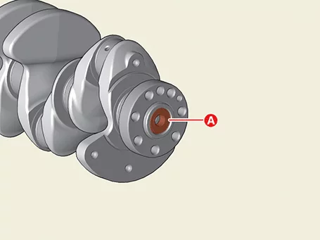
|
•
|
When removing the pilot bearing, the crankshaft may deform, so
always replace it
together.
|
|
•
|
Loads on the pilot bearing seal (B) or the inner lace (C) may
cause internal damage, so
always load the outer lace (A).
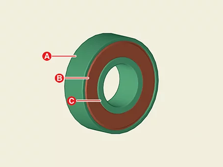
|
|
•
|
Insert the pilot bearing into the crankshaft as shown below.
|
Press depth (A)
: 1.5 mm (0.059 in.)
|
|
|
|
| 2.
|
Install the crankshaft position sensor wheel (A) and then tighten the bolts.
|
Specified torque :
12.7 - 13.7 N·m (1.3 - 1.4 kgf·m, 9.4 - 10.1 lb·ft)
|
|
| 3.
|
Install the main bearing.
|
The upper bearing has oil grooves and the lower bearings do not have oil
grooves.
|
| (1)
|
Install the upper bearings (A) by aligning the cylinder block groove and the
bearing protrusion.
|
| (2)
|
Install lower bearings (A) to match the main bearing cap groove and the bearing
protrusion.
|
Be careful not to change the cylinder block bearing and the
main bearing cap.
[#2, 4 Upper bearing]
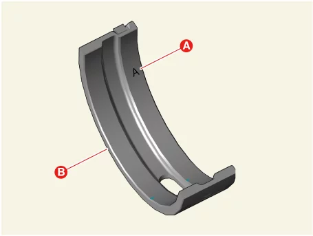
A : Mark
B : Color
[#1, 3, 5 Lower bearing]
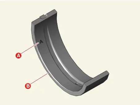
A : Mark
B : Color
[Lower bearing]
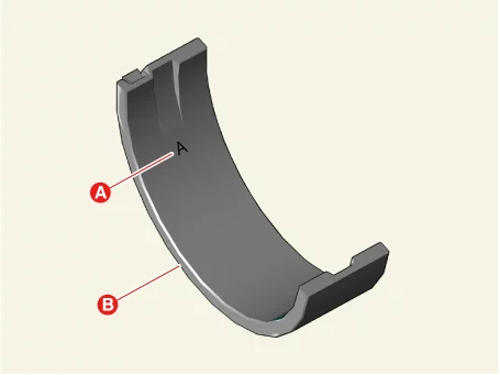
A : Mark
B : Color
|
|
|
| 4.
|
Install the thrust bearings.
Install the thrust bearings (A) under the cylinder block No. 4 journal, with the oil groove
facing
outward.
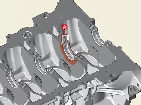
|
| 5.
|
Install the crankshaft (A) to the cylinder block.
|
| 6.
|
Install the cylinder block O-rings (A).
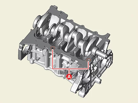
|
Do not reuse cylinder block O-ring (A)
|
|
| 7.
|
Apply liquid gasket to the lower crankcase mounting surface and then assemble within 5 minutes.
|
Bead width : 2.5 - 3.5 mm (0.0984 -
0.1378)
Sealant specifications : THREEBOND 1217H
/ LOCTITE 5900H
or equivalent
|
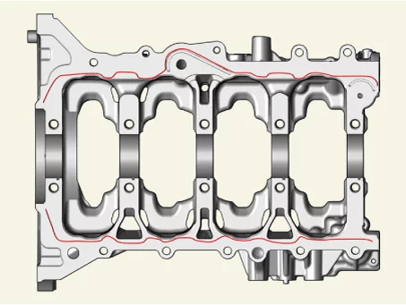
|
| 8.
|
Install the lower crankcase.
| (1)
|
Install the lower crankcase (A).
|
| (2)
|
Install the main bearing cap bolts.
|
Tightening torque
Step 1 : 27.5 - 31.4
N·m (2.8 - 3.2 kgf·m, 20.3 -
23.1 lb·ft)
Step 2 : 118 - 122°
|
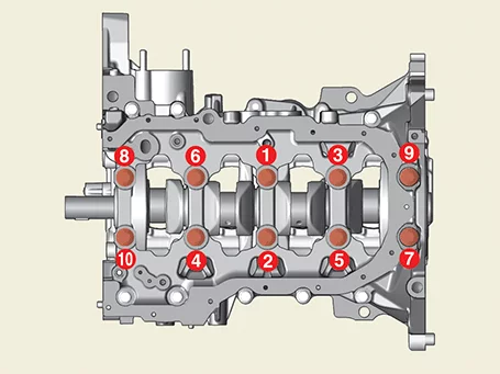
|
Do not reuse the main bearing cap bolts.
|
|
| (3)
|
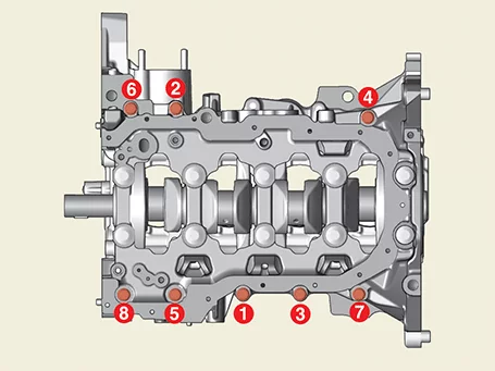
Install the lower crankcase bolts (A).
|
Tightening torque :
18.6 - 23.5 N·m (1.9 - 2.4 kgf·m, 13.7 - 17.4 lb·ft)
|
|
| (4)
|
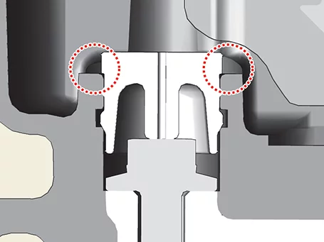
Install the rear cap (A).
|
•
|
When installing the rear cap, ensure that the
cylinder block mounting surface and
the rear cap mounting face match.
|
|
|
| (5)
|
Check if the crankshaft rotates smoothly.
|
|
| 9.
|
Check the crankshaft end play.
|
| 10.
|
Install the piston and connecting rod assembly.
(Refer to Cylinder Block - "Piston and Connecting Rod")
|
| 11.
|
Install in reverse order of removal.
|
Install the crankshaft to the specified torque.
|
|
•
|
When the cylinder block replaced with a new one, select the
proper crankshaft main
bearing and piston according to crankshaft journal bore mark and
cylinder bore size mark on
the cylinder block.
|
|
•
|
Connecting rod bearing selection.
(Refer to Cylinder Block -
"Piston and Connecting
Rod")
|
|
|
Crankshaft Inspection
|
•
|
This video was created using 3D graphics to help understand the vehicle
maintenance manual.
|
|
•
|
There may be some differences from actual vehicles.
|
|
•
|
The location and repair procedures of the parts may vary depending on vehicle
model, model year,
region, and specifications.
|
|
•
|
Check the KDS Guide for detailed information on how to use the KDS.
|
|
•
|
Check the manual for detailed maintenance procedures.
|
|
•
|
Unauthorized reproduction, distribution, or sharing of this video is
prohibited.
|
|
Crankshaft Inspection
(Click to play)
Video: Crankshaft Inspection
| 1.
|
Check the pilot bearing.
| (1)
|
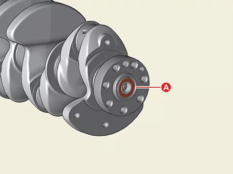
Visually check the pilot bearing (A) damaged.
|
| (2)
|
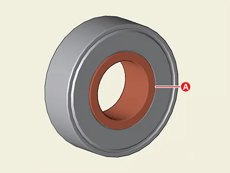
If there is noise or damage to the pilot bearing, replace the pilot bearing and
crankshaft
together.
|
| (3)
|
When removing the pilot bearing, the crankshaft may deform, so always replace
it together.
|
When removing the pilot bearing, the crankshaft may deform, so
always replace it
together.
|
|
|
| 2.
|
Measure the oil clearance of crankshaft bearing.
| (1)
|
Remove bearing and cap to measure the main journal bearing oil clearance.
|
| (2)
|
Clean each main journal and bearing using a cloth, etc.
|
| (3)
|
Place a piece of plastigauge in the axial direction of each main journal.
|
| (4)
|
Install the lower crankcase (A).
|
| (5)
|
Install the main bearing cap bolts (A).
|
Tightening torque
Step 1 : 27.5 - 31.4 N·m
(2.8 - 3.2 kgf·m, 20.3 -
23.1 lb·ft)
Step 2 : 118 - 122°
|
|
| (6)
|
Install the lower crankcase bolts (A).
|
Tightening torque :
18.6 - 23.5 N·m (1.9 - 2.4 kgf·m, 13.7 - 17.4 lb·ft)
|
|
| (7)
|
Measure the width of the plastigage at its widest point.
|
Bearing oil clearance :
0.010 - 0.028 mm (0.00039 - 0.00110 in.)
|
|
| (8)
|
If the measured value of the plastic gauge exceeds the specified value, replace
it with a new
bearing with the same classification color and re-measure the oil gap.
|
Do not adjust the clearance by machining the bearing or cap.
|
|
| (9)
|
If the remeasured value is still out of the specified value, install the next
larger or smaller
bearing and then remeasure the oil clearance.
|
•
|
If an appropriate oil gap cannot be obtained
even after installing a step larger
or smaller bearing, replace the crankshaft and
inspect again.
|
|
•
|
If the marks are indecipherable because of an
accumulation of dirt and dust, do
not scrub them with a wire brush or scraper.
Clean them only with solvent or
detergent.
|
|
Classification mark position for
crankshaft bore inner
diameter
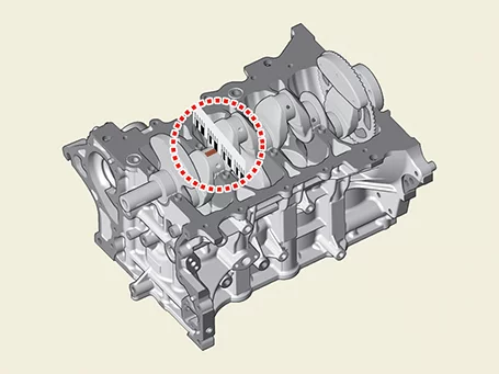
The each size mark of the 5 main journal bores is engraved on the side of
cylinder block.
Use the journal bore markings engraved on the block and the journal bore
markings on the
crankshaft for correct bearing selection.
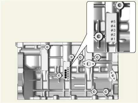
A : Crankshaft journal exterior diameter size mark
Cylinder Block Journal Bore
Classification Table
Class
|
Mark
|
Cylinder
block journal bore inner
diameter
|
a
|
A
|
50.000 - 50.006 mm (1.9685 - 1.9687 in.)
|
b
|
B
|
50.006 - 50.012 mm (1.9687 - 1.9690 in.)
|
c
|
C
|
50.012 - 50.018 mm (1.9690 - 1.9692 in.)
|
Crankshaft Main Journal
Classification Mark Location
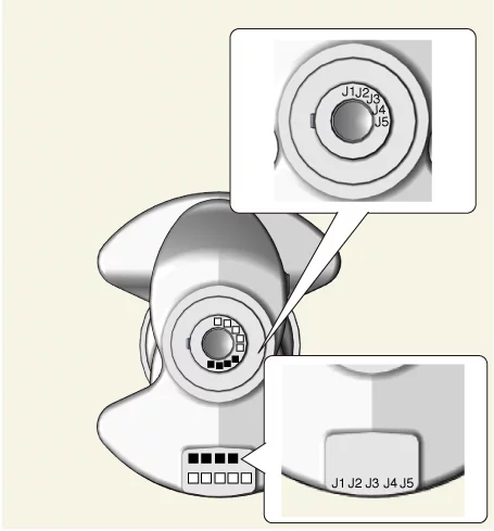
Crankshaft Main Journal
Classification Table
Class
|
Mark
|
Main journal
outer diameter
|
I
|
1
|
44.954 - 44.960 mm (1.7698 - 1.7701 in.)
|
II
|
2
|
44.948 - 44.954 mm (1.7696 - 1.7698 in.)
|
III
|
3
|
44.942 - 44.948 mm (1.7694 - 1.4363 in.)
|
Crankshaft Bearing Classification
Mark Location
[#2,4 Journal upper bearing]
A : Color
B : Mark
[#1, 3, 5 Journal upper bearing]
A : Color
B : Mark
[Lower bearing]
A : Color
B : Mark
Crankshaft Bearing Classification
Table
Classification
Mark
|
Classification
Color
|
Connecting
rod bearing
thickness
|
A
|
Blue
|
2.524 - 2.527 mm (0.0994 - 0.0994 in.)
|
B
|
Black
|
2.521 - 2.524 mm (0.0992 - 0.0994 in.)
|
C
|
No color
|
2.518 - 2.521 mm (0.0991 - 0.0992 in.)
|
D
|
Green
|
2.515 - 2.518 mm (0.0990 - 0.0991 in)
|
E
|
Red
|
2.512 - 2.515 mm (0.0988 - 0.0990 in.)
|
|
| (10)
|
Select the appropriate crank shaft main bearing using the bearing selection
table below.
Crankshaft Main Bearing Selection
Table
|
Main journal bore
classification mark
|
a (A)
|
b (B)
|
c (C)
|
Crankshaft Main Journal Classification Mark
|
I (1)
|
E
(Red)
|
D
(Green)
|
C
(No Color)
|
II (2)
|
D
(Green)
|
C
(No Color)
|
B
(Black)
|
III (3)
|
C
(No Color)
|
B
(Black)
|
A
(Blue)
|
|
|
| 3.
|
Measure the crankshaft end play.
Check the axial clearance by moving the crankshaft back and forth using a dial gauge.
|
Crankshaft end play : 0.10 - 0.28 mm
(0.0039 - 0.0110 in.)
|
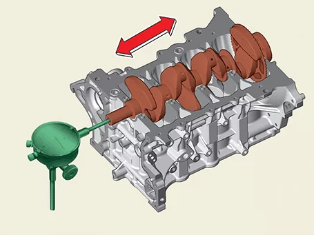
If end play exceeds limit value, replace the thrust bearing.
|
Thrust bearing thickness : 2.91 - 2.95
mm (0.1145 - 0.1161
in.)
|
|
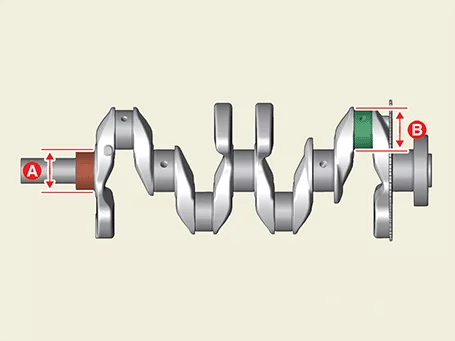
| 4.
|
Check the crankshaft main journals and pin journals.
Measure the outer diameter of the main journals (A) and pin journals (B) using a micrometer.
|
Main journal outer diameter : 44.942 -
44.960 mm (1.769 -
1.770 in.)
Pin journal diameter : 41.954 - 41.972
mm (1.651 - 1.652
in.)
|
|
Cylinder Block Disassembly
|
•
|
This video was created using 3D graphics to help understand the vehicle
maintenance manual.
|
|
•
|
There may be some differences from actual vehicles.
|
|
•
|
The location and repair procedures of the parts may vary depending on vehicle
model, model year,
region, and specifications.
|
|
•
|
Check the KDS Guide for detailed information on how to use the KDS.
|
|
•
|
Check the manual for detailed maintenance procedures.
|
|
•
|
Unauthorized reproduction, distribution, or sharing of this video is
prohibited.
|
|
Cylinder Block Removal and Disassembly
(Click to play)
Video: Cylinder Block Removal and
Disassembly
|
•
|
Use a fender cover to protect the painted surface.
|
|
•
|
Wait for the engine to cool to room temperature before disassembling to prevent
damage to the
cylinder head.
|
|
•
|
When handling a metal gasket, take care not to fold the gasket or damage the
contact surface of
the gasket.
|
|
•
|
Be careful not to damage the connector when disconnecting.
|
|
|
•
|
Mark all wiring and hoses to prevent incorrect connections.
|
|
•
|
Rotate the crankshaft to place the no.1 cylinder piston at the compress TDC.
|
|
| 1.
|
Remove the engine and transaxle assembly.
(Refer to Engine and Transaxle Assembly - "Engine and Transaxle
Assembly")
|
| 2.
|
Remove the automatic transaxle.
(Refer to Automatic Transaxle System - "Automatic
Transaxle")
|
| 3.
|
Remove the drive plate.
(Refer to Cylinder Block - "Drive plate")
|
| 4.
|
Remove the rear oil seal.
(Refer to Cylinder Block - "Rear Oil Seal")
|
| 5.
|
Install the engine on the engine stand for disassembly.
|
| 6.
|
Remove the intake manifold.
(Refer to Intake and Exhaust System - "Intake Manifold")
|
| 7.
|
Remove the turbo manifold.
(Refer to Intake and Exhaust System - "Turbo Manifold")
|
| 8.
|
Remove the cylinder head cover.
(Refer to Cylinder Head Assembly - "Cylinder Head
Cover")
|
| 9.
|
Remove the oil pan.
(Refer to Lubrication - "Oil Pan")
|
| 10.
|
Remove the timing chain.
(Refer to Timing System - "Timing Chain Cover")
|
| 11.
|
Remove the Integrated Thermal Management Module (ITM).
(Refer to Cooling System - "Integrated Thermal Management
Module
(ITM)")
|
| 12.
|
Remove the cylinder head.
(Refer to Cylinder Head Assembly - "Cylinder Head")
|
| 13.
|
Remove the oil pump.
(Refer to Lubrication System - "Oil Pump")
|
| 14.
|
Remove the oil filter & oil cooler.
(Refer to Lubrication System - "Oil filter & oil
cooler")
|
| 15.
|
Remove the piston and connecting rod.
(Refer to Cylinder Block - "Piston and Connecting Rod")
|
| 16.
|
Remove the crankshaft.
(Refer to Cylinder Block - "Crankshaft")
|
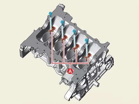
| 17.
|
Remove the piston cooling oil jet (A) after removing the bolts.
|
Specified torque :
8.8 - 12.7 N·m (0.9 - 1.3 kgf·m, 6.5 - 9.4 lb·ft)
|
|
Cylinder Block Reassembly
|
•
|
Thoroughly clean all parts to be assembled.
|
|
•
|
Apply new engine oil to the rotating surface before installing the parts.
|
|
•
|
Do not reuse the gasket, O-ring and oil seal.
|
|
| 1.
|
install the piston cooling oil jet (A) after installing the bolts.
|
Specified torque :
8.8 - 12.7 N·m (0.9 - 1.3 kgf·m, 6.5 - 9.4 lb·ft)
|
|
| 2.
|
Install the crankshaft.
(Refer to Cylinder Block - "Crankshaft")
|
| 3.
|
Check the crankshaft end play.
(Refer to Cylinder Block - "Crankshaft")
|
| 4.
|
Remove the lower crankcase and then inspect the oil clearance of crankshaft bearing.
(Refer to Cylinder Block - "Crankshaft")
|
| 5.
|
Install the piston and connecting rod assembly.
(Refer to Cylinder Block - "Piston and Connecting Rod")
|
| 6.
|
Inspect the oil clearance of connecting rod bearing cap.
(Refer to Cylinder Block - "Piston and Connecting Rod")
|
| 7.
|
Inspect the connecting rod end play.
(Refer to Cylinder Block - "Piston and Connecting Rod")
|
| 8.
|
Install in reverse order of removal.
|
Install the cylinder block to the specified torque.
|
|
|
•
|
When replacing the cylinder block, select and install the appropriate
crankshaft main bearings
and pistons according to the crankshaft journal bore mark and the cylinder bore
size mark on the
cylinder block.
|
|
•
|
Crankshaft main bearing selection.
(Refer to Cylinder Block - "Crankshaft")
|
|
•
|
Connecting rod bearing selection.
(Refer to Cylinder Block - "Piston and
Connecting Rod")
|
|
Cylinder Block Inspection
|
•
|
This video was created using 3D graphics to help understand the vehicle
maintenance manual.
|
|
•
|
There may be some differences from actual vehicles.
|
|
•
|
The location and repair procedures of the parts may vary depending on vehicle
model, model year,
region, and specifications.
|
|
•
|
Check the KDS Guide for detailed information on how to use the KDS.
|
|
•
|
Check the manual for detailed maintenance procedures.
|
|
•
|
Unauthorized reproduction, distribution, or sharing of this video is
prohibited.
|
|
Cylinder Block Inspection
(Click to play)
Video: Cylinder Block Inspection
| 1.
|
Remove the gasket debris on the top of cylinder block using a scraper.
|
| 2.
|
Using a soft brush and solvent, thoroughly clean the cylinder block.
|
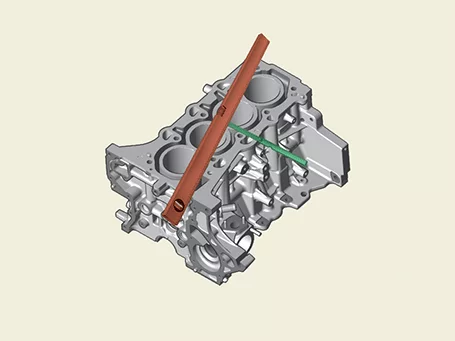
| 3.
|
Measure the flatness of the top surface of cylinder block.
Measure the flatness of the surface in contact with the cylinder head gasket using the precise
square
ruler and feeler gauge.
|
Flatness of cylinder block gasket face
Total : 0.05 mm (0.0020 in) or less
100 mm × 100 mm (3.9370 in. x 3.9370 in.) : 0.02 mm (0.0008 in.) or less
|
|
| 4.
|
Visually inspect the inside of cylinder bore for scratches, etc., and replace the cylinder
block if
noticeable scratches are found.
|
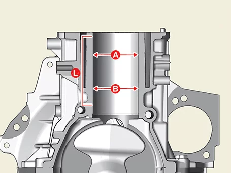
| 5.
|
Using a cylinder bore gauge, measure the inner diameter points A and B of the cylinder bore in
the axial
and vertical directions.
|
Specified value : 75.60 - 75.63 mm
(2.9764 - 2.9776 in.)
|
|
L : The straight distance between the
piston TDC NO.1 ring
and BDC oil ring.
A : 1/4 point of L.
B : 3/4 point of L.
|
|
Other information:
Kia K4 (CL4) 2025-2026 Service Manual: Tilt and telescopic steering wheel
The Kia K4 features a highly adjustable tilt and telescopic steering wheel, allowing you to fine-tune the driving position to your exact preferences before setting off. This versatile system also enables you to raise the wheel to its highest position, providing additional legroom for effortless entry and exit from the Kia K4.
For the safest and most comfortable driving experience, the steering wheel should be positioned so that it feels natural during operation while ensuring you have a clear, unobstructed view of all instrument panel gauges and warning lights.
Kia K4 (CL4) 2025-2026 Service Manual: General Safety Information and Caution
Precaution (R-134a)
When Handling Refrigerant
1.
R-134a liquid refrigerant is highly volatile. A drop on the skin of your hand could result in
localized
frostbite. When handling the refrigerant, be sure to wear gloves.
2.