Contents:
Components and Components Location
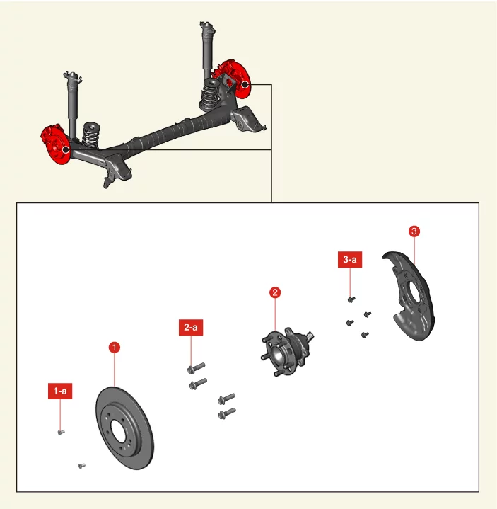
1. Rear Brake Disc
1-a. 4.9 - 5.9 N·m (0.5
- 0.6
kgf·m, 3.6 - 4.3 lb·ft, 43.4 - 52.1 lb·in)
2. Rear Hub Assembly
2-a. 49.0 - 58.8 N·m (5.0 -
6.0 kgf·m,
36.2 - 43.4 lb·ft)
|
3. Rear Dust Cover
3-a. 6.9 - 10.8 N·m (0.7
- 1.1
kgf·m, 5.1 - 8.0 lb·ft, 60.8 - 95.5 lb·in)
|
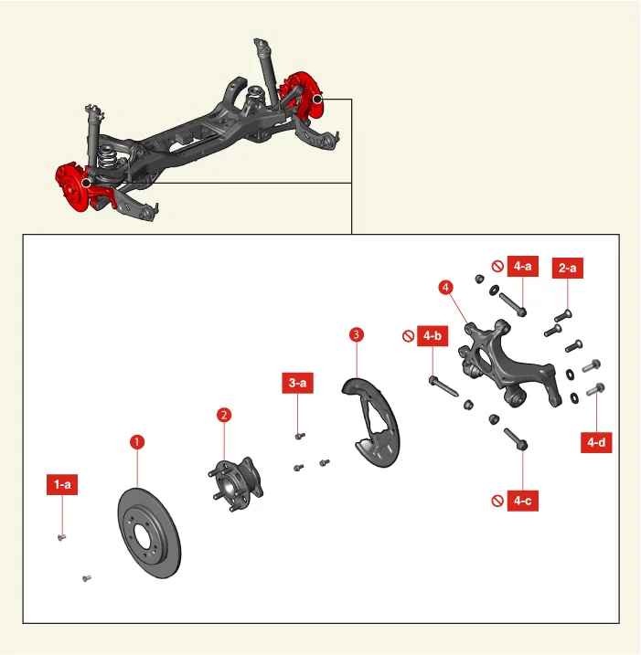
1. Rear Brake Disc
1-a. 4.9 - 5.9 N·m (0.5
- 0.6
kgf·m, 3.6 - 4.3 lb·ft, 43.4 - 52.1 lb·in)
2. Rear Hub Assembly
2-a. 88.3 - 107.9 N·m (9.0 -
11.0 kgf·m,
65.1 - 79.6 lb·ft)
3. Rear Dust Cover
3-a. 6.9 - 10.8 N·m (0.7 - 1.1 kgf·m, 5.1 - 8.0 lb·ft,
60.8 -
95.5 lb·in)
|
4. Rear Carrier
4-a. 44.1 - 53.9 N·m (4.5 -
5.5
kgf·m, 32.5 - 39.8 lb·ft) + 355 - 365°
4-b. 44.1 - 53.9 N·m (4.5 - 5.5 kgf·m, 32.5 - 39.8 lb·ft)
+ 355 -
365°
4-c. 6.5 - 7.5 N·m (6.5 - 7.5 kgf·m, 47.0 - 55.0 lb·ft) + 175 - 185°
4-d. 137.3 - 156.9
N·m (14.0 -
16.0 kgf·m, 101.3 - 115.7 lb·ft)
|
Rear Carrier Removal and Installation
|
If a transmission jack is used with a two-post lift, do not lift the vehicle too much. The
center gravity
of the vehicle may change and fall.
|
| 1.
|
Remove the rear dust cover. [Multi-link Type]
(Refer to Rear Axle Assembly - "Rear Dust Cover")
|
| 2.
|
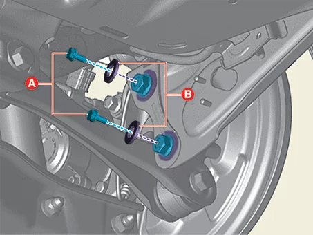
Remove the rear trailing arm bolts (A) and wahsers (B).
|
Tightening torque :
137.3 - 156.9 N·m (14.0 - 16.0 kgf·m, 101.3 - 115.7 lb·ft)
|
|
| 3.
|
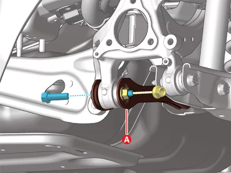
Separate the rear assist arm (A) after removing the bolt and nut.
|
Tightening torque :
63.7 - 73.5 N·m (6.5 - 7.5 kgf·m, 47.0 - 55.0 lb·ft) + 175 - 185°
|
|
•
|
Do not reuse the bolt and nut.
|
|
•
|
Install the transmission jack and lift up the parts to prevent
the bolt and nut from
damage when installing or removing.
|
|
•
|
Be careful not to change the bolt and nut installing position.
|
|
|
Fix the bolt and remove or install the nut.
|
|
| 4.
|
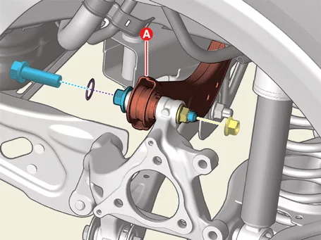
Separate the rear upper arm (A) after removing the bolt, nut and washer.
|
Tightening torque :
44.1 - 53.9 N·m (4.5 - 5.5 kgf·m, 32.5 - 39.8 lb·ft) + 355 - 365°
|
|
•
|
Do not reuse the bolt and nut.
|
|
•
|
Install the transmission jack and lift up the parts to prevent
the bolt and nut from
damage when installing or removing.
|
|
•
|
Be careful not to change the bolt, nut and washer installing
position.
|
|
|
Fix the bolt and remove or install the nut.
|
|
| 5.
|
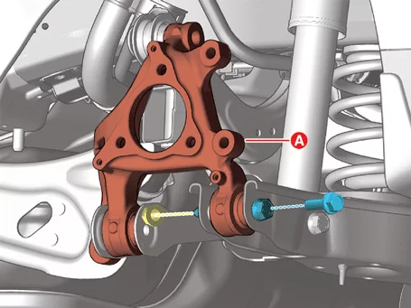
Remove the rear carrier (A) after removing the bolt and nut.
|
Tightening torque :
44.1 - 53.9 N·m (4.5 - 5.5 kgf·m, 32.5 - 39.8 lb·ft) + 355 - 365°
|
|
•
|
Do not reuse the bolt and nut.
|
|
•
|
Install the transmission jack and lift up the parts to prevent
the bolt and nut from
damage when installing or removing.
|
|
•
|
Be careful not to change the bolt and nut installing position.
|
|
|
Fix the bolt and remove or install the nut.
|
|
| 1.
|
Install in the reverse order of removal.
|
Install to the specified torque.
|
|
| 2.
|
Check the alignment.
(Refer to Suspension System - "Alignment")
|
Rear Carrier Inspection
| 1.
|
Check the rear carrier for cracks.
|
Rear Hub Assembly Removal and Installation - Torsion Beam Axle
| 1.
|
Remove the rear brake disc.
(Refer to Brake System - "Rear Brake Disc")
|
| 2.
|
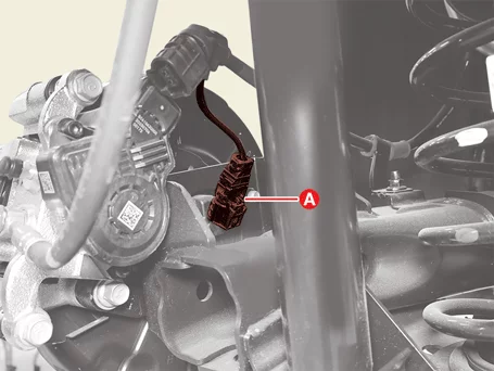
Disconnect the rear wheel speed sensor connector (A).
|
| 3.
|
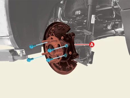
Remove the rear hub assembly (A) after removing the bolts.
|
Tightening Torque :
49.0 - 58.8 N·m (5.0 - 6.0 kgf·m, 36.2 - 43.4 lb·ft)
|
|
| 1.
|
Install in the reverse order of removal.
|
Install to the specified torque.
|
|
Rear Hub Assembly Removal and Installation - Multi Link
| 1.
|
Remove the rear wheel and tires.
(Refer to Suspension System - "Wheel")
|
| 2.
|
Remove the rear brake disc.
(Refer to Brake System - "Rear Brake Disc")
|
| 3.
|
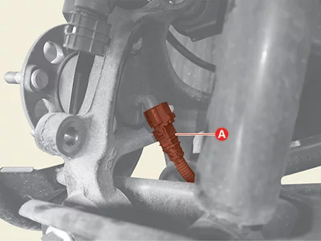
Disconnect the rear wheel speed sensor connector (A).
|
| 4.
|
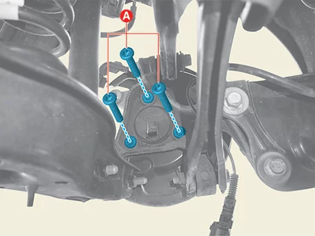
Remove the rear hub assembly bolts (A).
|
Tightening torque :
88.3 - 107.9 N·m (9.0 - 11.0 kgf·m, 65.1 - 79.6 lb·ft)
|
|
| 5.
|
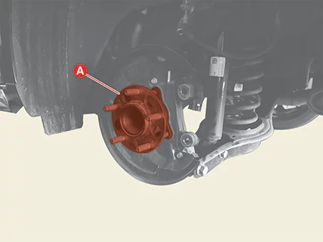
Remove the rear hub assembly (A).
|
| 1.
|
Install in the reverse order of removal.
|
Install to the specified torque.
|
|
Rear Hub Assembly Inspection
| 1.
|
Check the rear hub assembly for wear and damage.
|
Rear Dust Cover Removal and Installation - Torsion Beam Axle
| 1.
|
Remove the rear hub assembly.
(Refer to Rear Axle Assembly - "Rear Hub Assembly")
|
| 2.
|
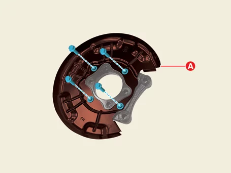
Remove the rear dust cover (A) after removing the bolts.
|
Tightening torque :
6.9 - 10.8 N·m (0.7 - 1.1 kgf·m, 5.1 - 8.0 lb·ft, 60.8 - 95.5 lb·in)
|
|
| 1.
|
Install in the reverse order of removal.
|
Install to the specified torque.
|
|
Rear Dust Cover Removal and Installation - Multi Link
| 1.
|
Remove the rear hub assembly.
(Refer to Rear Axle Assembly - "Rear Hub Assembly")
|
| 2.
|
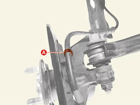
Remove the EPB extension wire clip (A) from the dust cover.
|
| 3.
|
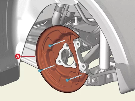
Remove the rear dust cover (A) after removing the bolts.
|
Tightening torque :
6.9 - 10.8 N·m (0.7 - 1.1 kgf·m, 5.1 - 8.0 lb·ft, 60.8 - 95.5 lb·in)
|
|
| 1.
|
Install in the reverse order of removal.
|
Install to the specified torque.
|
|
Rear Dust Cover Inspection
| 1.
|
Check the rear dust cover for scratches or damage.ds
|
Other information:
Kia K4 (CL4) 2025-2026 Service Manual: Integrated memory system
The Kia K4 is equipped with a sophisticated Integrated Memory System (IMS) designed to enhance your driving comfort. This feature allows you to store and recall personalized driving settings for multiple drivers with a simple, one-touch operation, ensuring that your Kia K4 always feels tailored to your preferences.
The system stores the following configurations:
Driver’s seat position (height, recline, and slide)
Outside rearview mirror angles
WARNING
For your safety, never attempt to operate the Integrated Memory System while the Kia K4 is in motion.
Kia K4 (CL4) 2025-2026 Service Manual: If you have a flat tire (with spare tire)
If you encounter a flat tire while driving your Kia K4, you can utilize the onboard emergency tools to replace the damaged tire with the spare tire stored in your vehicle.
WARNING
Driving on a flat tire causes permanent structural damage to the tire carcass. Never attempt to reinflate a tire that has been driven on while severely underinflated or flat, as this significantly increases the risk of a blowout and a serious crash.