Contents:
Rear Coil Spring Components and Components Location
| Component and Component Location |
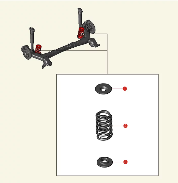
1. Rear Coil Spring Upper Pad
2. Rear Coil
Spring
3. Rear Coil Spring Lower Pad
|
|
Rear Coil Spring Removal and Installation
| 1.
|
Remove the rear wheel and tires.
(Refer to Wheel and Tire - "Wheel")
|
| 2.
|
Remove the rear shock absorber bolts (A).
|
Tightening torque :
98.1 - 117.7 N·m (10.0 - 12.0 kgf·m, 72.3 - 86.8 lb·ft)
|
[LH]
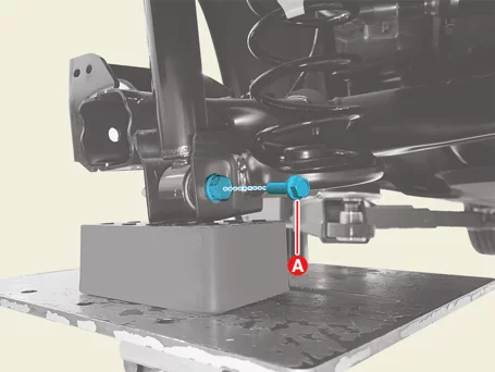
[RH]
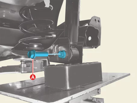
|
| 3.
|
Remove the rear coil spring and pad (A).
[LH]
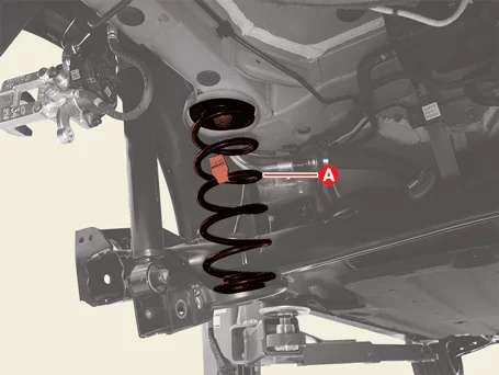
[RH]
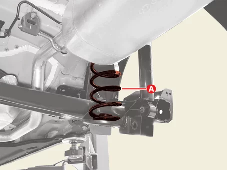
|
| 1.
|
Install in the reverse order of removal.
|
Install to the specified torque.
|
|
Rear Coil Spring Inspection
| 1.
|
Check the coil spring for cracks or deformation.
|
| 2.
|
Check the coil spring pad for damage and deformation.
|
Rear Torsion Beam Axle Components and Components Location
| Component and Component Location |
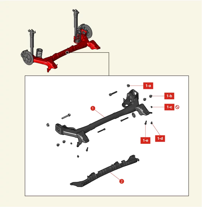
1. Rear Torsion Beam Axle
1-a. 98.1 - 117.7
N·m
(10.0 - 12.0 kgf·m, 72.3 - 86.8 lb·ft)
1-b. 98.1 - 117.7 N·m (10.0 - 12.0 kgf·m, 72.3 - 86.8
lb·ft)
1-c.
63.7 - 73.5 N·m (6.5 - 7.5 kgf·m, 47.0 - 54.2 lb·ft) + 265 - 275°
1-d. 49.0 - 63.7 N·m (5.0 - 6.5
kgf·m,
36.2 - 47.0 lb·ft)
1-e. 98.1 - 117.7 N·m (10.0 - 12.0 kgf·m, 72.3 - 86.8 lb·ft)
|
2. Rear Torsion Beam Axle Under Cover
|
Rear Torsion Beam Axle Removal and Installation
|
•
|
This video was created using 3D graphics to help understand the vehicle
maintenance manual.
|
|
•
|
There may be some differences from actual vehicles.
|
|
•
|
The location and repair procedures of the parts may vary depending on vehicle
model, model year,
region, and specifications.
|
|
•
|
Check the KDS Guide for detailed information on how to use the KDS.
|
|
•
|
Check the manual for detailed maintenance procedures.
|
|
•
|
Unauthorized reproduction, distribution, or sharing of this video is
prohibited.
|
|
Rear Torsion Beam Axle (Disc Type)
(Click to play)

Video: Rear Torsion Beam Axle (Disc Type)
Rear Torsion Beam Axle (Drum Type)
(Click to play)
Video: Rear Torsion Beam Axle (Drum Type)
| 1.
|
Remove the rear hub assembly.
(Refer to Driveshaft and Axle - "Rear Hub Assembly")
|
| 2.
|
Remove the rear coil springs.
(Refer to Rear Suspension System - "Rear Coil Spring")
|
| 3.
|
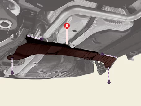
Remove the torsion beam axle under cover (A).
| (1)
|
Separate the torsion beam axle under cover locking clip (B).
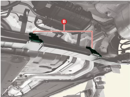
|
| (2)
|
Remove the torsion beam axle under cover (A) after removing the fasteners.
|
|
| 4.
|
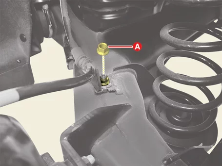
Remove the rear wheel speed sensor after removing the nut (A).
|
Tightening torque :
8.8 - 13.7 N·m (0.9 - 1.4 kgf·m, 6.5 - 10.1 lb·ft)
|
|
| 5.
|
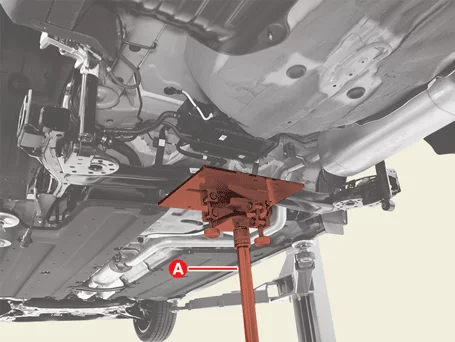
Support the torsion beam axle with a suitable jack (A).
|
| 6.
|
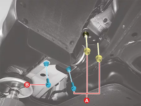
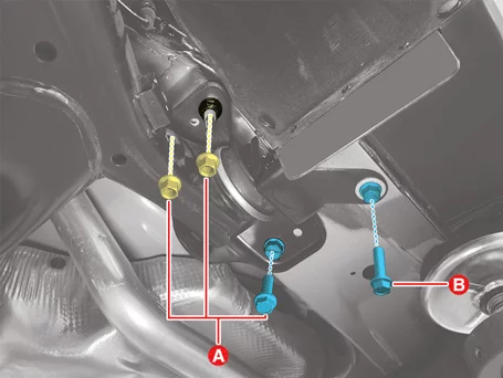
Remove the torsion beam axle stay bolts and nuts (A, B).
|
Tightening torque :
(A) : 98.1 - 117.7 N·m (10.0 - 12.0 kgf·m, 72.3 - 86.8 lb·ft)
(B) : 49.0 - 63.7 N·m (5.0 - 6.5 kgf·m, 36.2 - 47.0 lb·ft)
|
|
| 7.
|
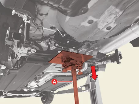
Remove the torsion beam axle by lowering the jack (A).
|
Check if there is no interfere with surrounding parts when removing or
installing the torsion
beam axle.
|
|
| 8.
|
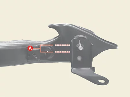
Mark (A) between the torsion beam axle stay and the torsion beam axle.
|
| 9.
|
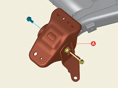
Remove the rear torsion beam axle stay (A) after removing the bolt and nut.
|
Tightening torque :
63.7 - 73.5 N·m (6.5 - 7.5 kgf·m, 47.0 - 54.2 lb·ft) + 265 - 275°
|
|
Do not reuse the bolt and nut.
|
|
| 1.
|
Install in the reverse order of removal.
|
Install to the specified torque.
|
|
Rear Torsion Beam Axle Replacement
CTBA (Coupled Torsion Beam Axle) Bushing
Tool Name / Number
|
Illustration
|
Description
|
CTBA bushing remover & installer
09551 - AL100
|
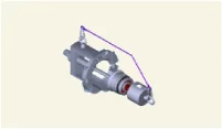
|
Used for removal or installing of the CTBA bushing
|
|
•
|
Make sure the main bolt and nut threads are clean before using.
|
|
•
|
The main bolt and nut should be lubricated each time it is used.
|
|
•
|
After use, cool the main bolt and nut every time to prevent overheating. It can
be damaged.
|
|
SST List
* Refer to the table below for the SST numbers used in the
replacement
procedure.
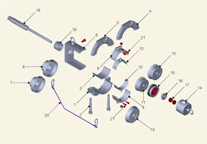
1. Beam Clamp A
2. Beam Clamp
Bolt
3. Beam
Clamp Adaptor
4. Beam Clamp B
5. Beam Clamp C
6. Installer Adaptor A
7. Installer
Adaptor B
|
8. Beam Clamp Support
9. Bushing
Guide
A
10. Bushing Guide B
11. Remover Adaptor A
12. Remover Adaptor B
13. Installer Adaptor
C
14.
Safety Cap
|
15. Bearing
16. Bearing Washer
17.
Nut
18. Main Bolt
19. Main Nut
20. Safety Wire
21. Bushing Guide Bolt
|
| 1.
|
Remove the rear torsion beam axle.
(Refer to Rear Suspension System - "Rear Torsion Beam Axle")
|
| 2.
|
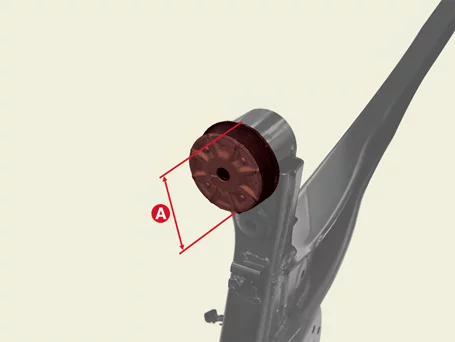
Measure the outer diameter (A) of the CTBA bushing.
|
| 3.
|
Refer to the following table and prepare the SST according to the size of the bushing outer
diameter.
|
Type 1 : 78.0 mm (3.0708 in.)
Type 2 : 84 mm (3.3070 in.)
|
Type
|
Outer Diameter
|
SST
|
Type 1
|
78 mm (3.0708 in.)
|
1, 3, 5, 7, 8, 11, 13, 14, 15, 16, 17, 18, 19, 20
|
Type 2
|
84 mm (3.3070 in.)
|
1, 4, 6, 8, 11, 13, 14, 15, 16, 17, 18, 19, 20
|
|
| 4.
|
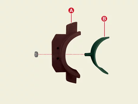
Install the SST[3] (B) to the SST[1] (A) by tightening the nut. [Type 1
Only]
|
| 5.
|
Pre-install the SST[1] (B) to the SST[5 or 4] (A) by tightening the bolts[2].
Type 1 : SST [5]
Type 2 : SST [4]
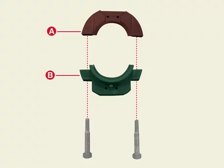
|
| 6.
|
Install the SST[5 or 4 + 1] (A) to the outside of the bushing.
Type 1 : SST [5, 1]
Type 2 : SST [4, 1]
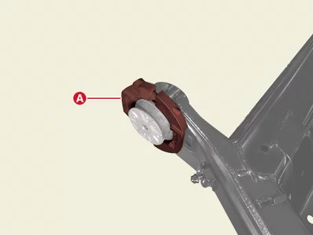
|
| 7.
|
Install SST [8,19,18] (A) to SST [5 or 4 + 1] by passing through the bushing inner diameter.
Type 1 : SST [5, 1]
Type 2 : SST [4, 1]
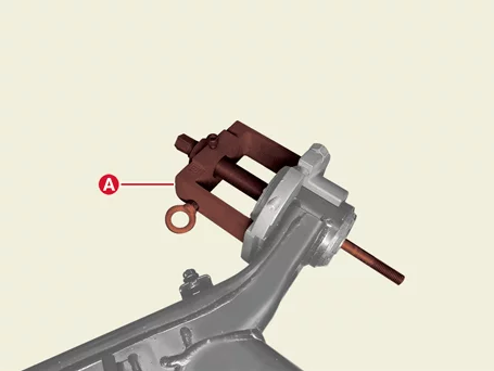
|
| 8.
|
Install the SST[11] (A) to the SST[18].
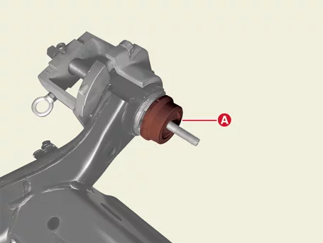
|
| 9.
|
Install the SST[15] (A) to the SST[18].
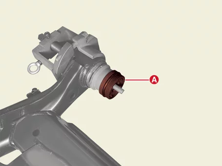
|
| 10.
|
Install the SST[16] (A) to the SST[18].
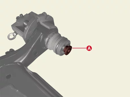
|
| 11.
|
Install the 2 SST[17] (A) to the SST[18].
|
Tightening torque : 49.0 N·m (5.0 kgf·m,
36.2 lb·ft)
|
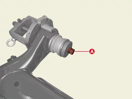
|
The end of SST[17] (A) and SST[18] should be aligned in straight line.
|
|
| 12.
|
Install the SST[14] (A).
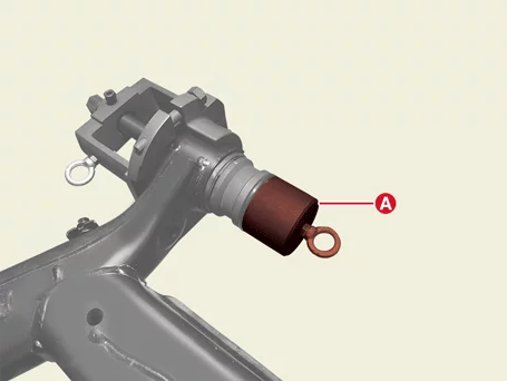
|
| 13.
|
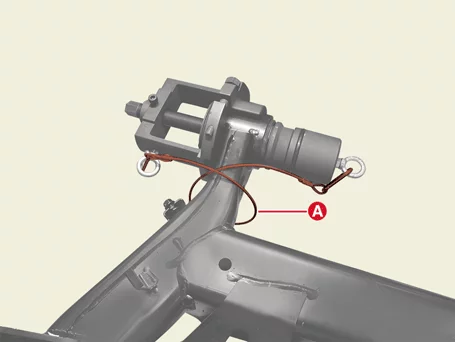
Install the SST[20] (A) to the 2 hooks as shown as below.
|
If the SST [20] is not installed properly, injury may occur.
|
|
| 14.
|
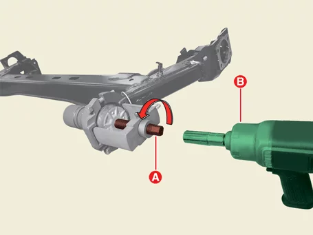
Rotate the bolt (A) counter clockwise using an impact wrench (B) to remove the bushing.
|
| 15.
|
Remove the SST[20] (A).
|
| 16.
|
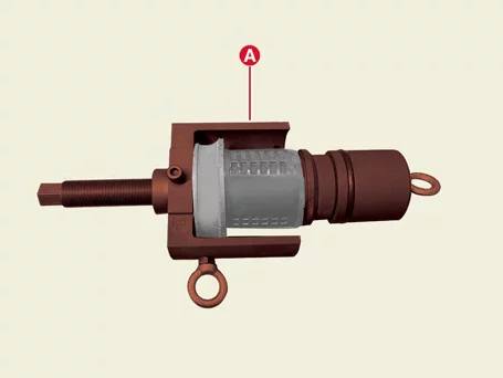
Remove the SST[1, 4 or 5,8,18,19] (A) from the bushing.
Remove the SST[1, 4 or 5,8,18,19] (A) from the bushing.
Type 1 : SST [5]
Type 2 : SST [4]
|
| 17.
|
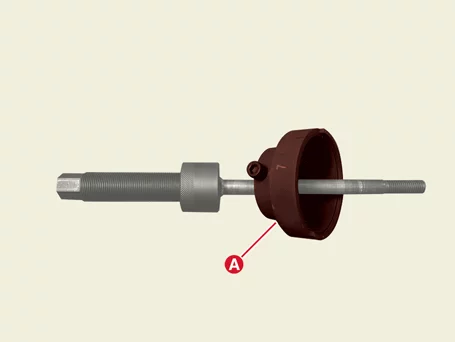
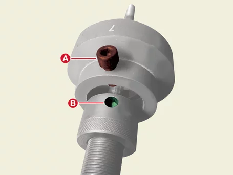
Install the SST[6 or 7] (A) to the SST[18,19].
Type 1 : SST [7]
Type 2 : SST [6]
|
Install the SST[6 or 7] bolt (A) to the SST[19] hole (B).
|
|
| 18.
|
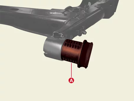
Install the new bushing (A) to the CTBA.
|
| 19.
|
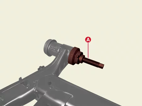
Install the SST[7,18] (A) by passing through the bushing inner diameter.
|
| 20.
|
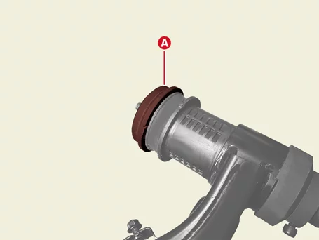
Install the SST[13] (A) to the SST[18].
|
| 21.
|
Install the SST[15] (A) to the SST[18].
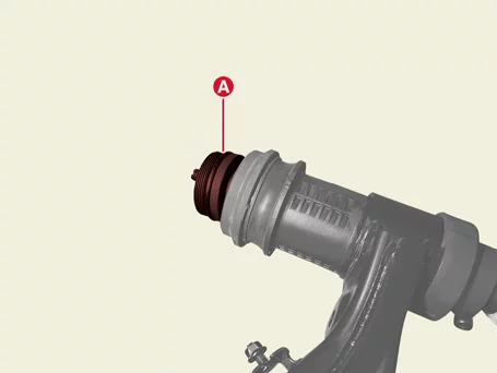
|
| 22.
|
Install the SST[16] (A) to the SST[18].
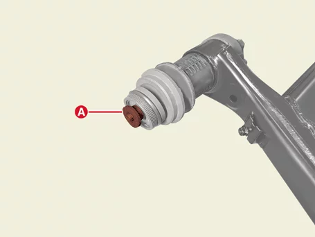
|
| 23.
|
Install the 2 SST[17] to the SST[18].
|
Tightening torque : 49.049.049.049.0 N·m
(5.0 kgf·m, 36.2
lb·ft)
|
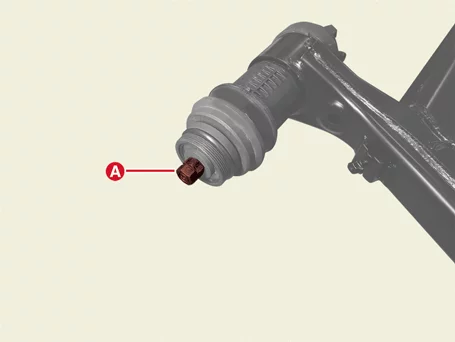
The end of SST[17] (A) and SST[18] should be aligned in straight line.
|
| 24.
|
Install the SST[14] (A).
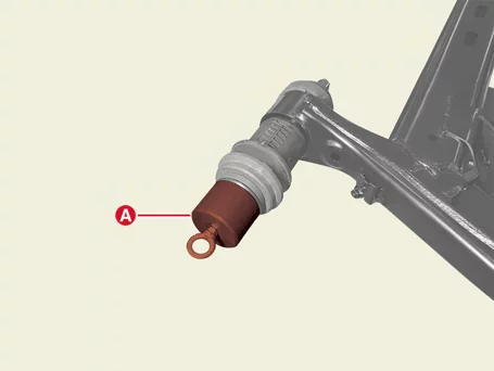
|
| 25.
|
Install the SST[20] (A) to the 2 hooks as shown as below.
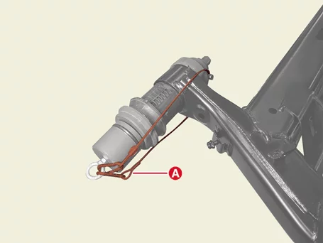
|
If the SST [20] is not installed properly, injury may occur.
|
|
| 26.
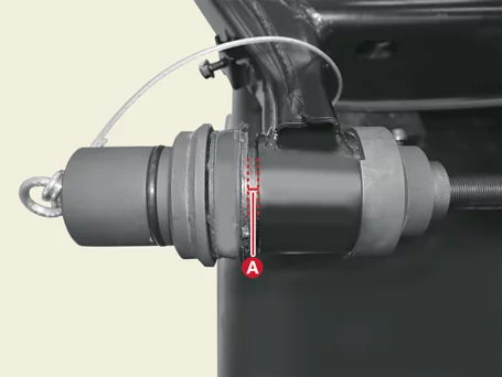
|
Install the new CTBA bushing by rotating the main bolt (A) counter clockwise using the impact
wrench (B).
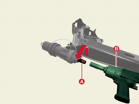
|
Install the bushing until there is no gap (A) between the bushing and CTBA.
|
|
Rear Torsion Beam Axle Inspection
| 1.
|
Check the bushing for wear or aging.
|
| 2.
|
Check all bolts and nuts.
|
Rear Shock Absorber Components and Components Location
| Component and Component Location |
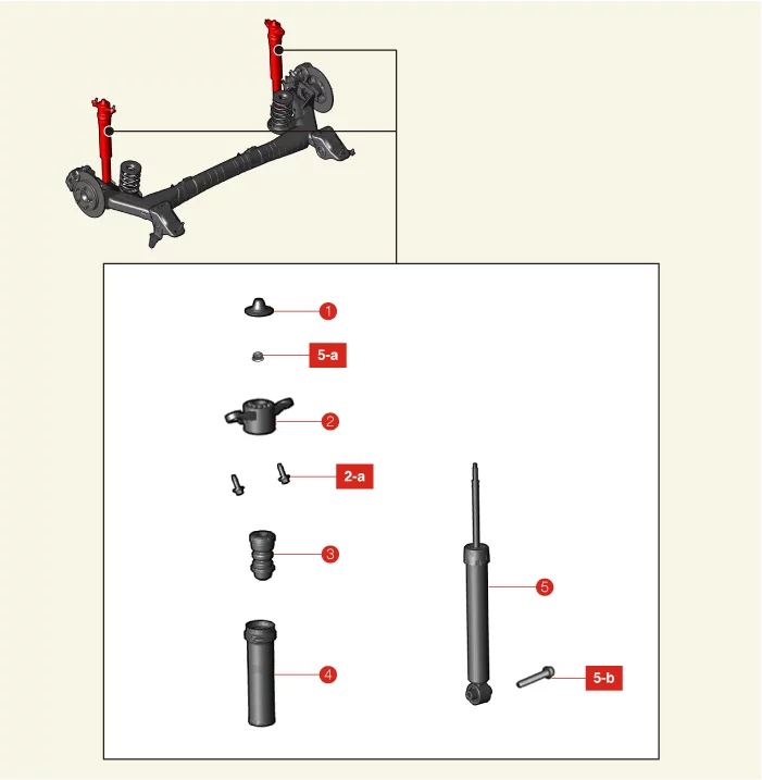
1. Insulator Cap
2. Insulator
2-a. 58.8
- 73.5
N·m (6.0 - 7.5 kgf·m, 43.4 - 54.2 lb·ft)
|
3. Bumper Rubber
4. Dust Cover
5. Shock
Absorber
Assembly
5-a. 19.6 - 24.5 N·m (2.0 - 2.5 kgf·m, 14.5 - 18.1 lb·ft)
5-b. 98.1 - 117.7 N·m (10.0
- 12.0
kgf·m, 72.3 - 86.8 lb·ft)
|
Rear Shock Absorber Removal and Installation
| 1.
|
Remove the rear wheel and tires.
(Refer to Wheel and Tire - "Wheel")
|
| 2.
|
Remove the rear shock absorber bolt (A).
|
Tightening torque :
98.1 - 117.7 N·m (10.0 - 12.0 kgf·m, 72.3 - 86.8 lb·ft)
|
|
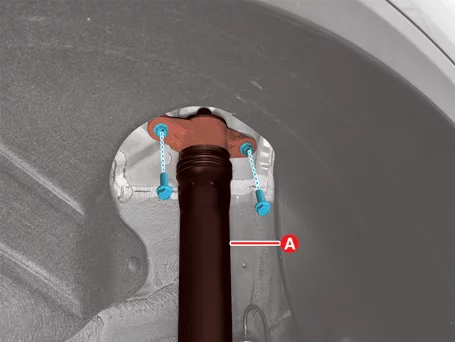
| 3.
|
Remove the rear shock absorber (A) after removing the bolts.
|
Tightening torque :
58.8 - 73.5 N·m (6.0 - 7.5 kgf·m, 43.4 - 54.2 lb·ft)
|
|
| 1.
|
Install in reverse order of removal.
|
Install to the specified torque.
|
|
Rear Shock Absorber Disassembly
Tool Name / Number
|
Illustration
|
Description
|
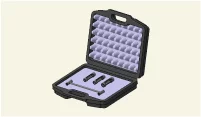
Shock absorber lock nut remover.
09546 - 3X100
|
|
Used for removal or installing of rear shock absorber lock nut.
|
| 1.
|
Remove the rear shock absorber.
(Refer to Rear Suspension System - "Rear Shock
Absorber")
|
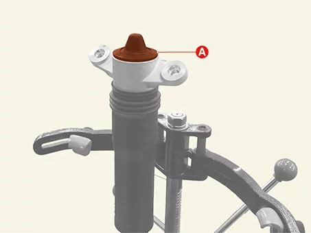
| 2.
|
Remove the insulator cap (A).
|
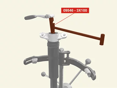
| 3.
|
Remove the self locking nut using the SST (09546 - 3X100).
|
Tightening torque :
19.6 - 24.5 N·m (2.0 - 2.5 kgf·m, 14.5 - 18.1 lb·ft)
|
|
Do not reuse the lock nut.
|
|
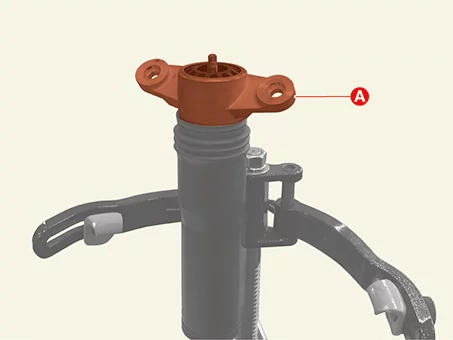
| 4.
|
Remove the insulator (A).
|
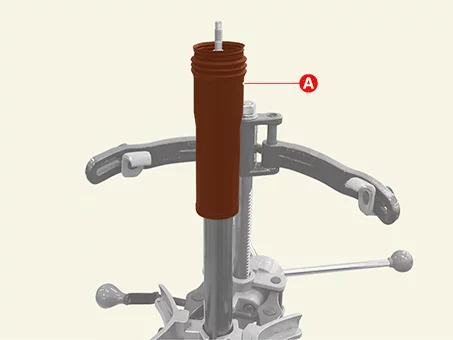
| 5.
|
Remove the dust cover (A).
|
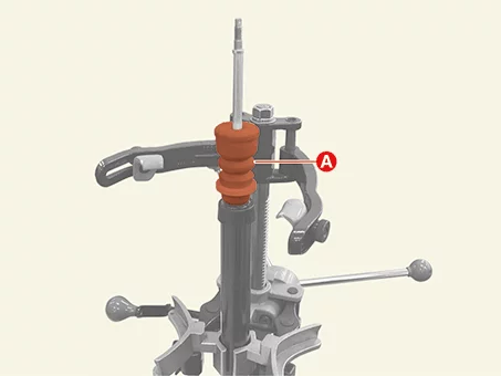
| 6.
|
Remove the bumper stopper (A).
|
| 7.
|
Refer to the table below and disassemble the rear shock absorber assembly.
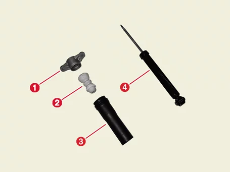
Disassembling Orders :
1 → 2 → 3 → 4
Number
|
Item
|
1
|
Insulator
|
2
|
Bumper rubber
|
3
|
Dust cover
|
4
|
Shock absorber assembly
|
|
Rear Shock Absorber Inspection
| 1.
|
Check the rubber parts for damage or deterioration.
|
| 2.
|
Check all bolts and nuts.
|
| 3.
|
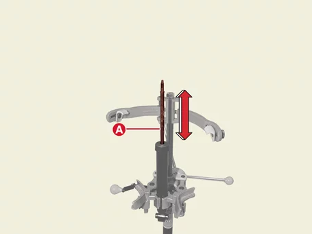
Repeat compression and tension of the rear shock absorber rod (A) to check for abnormal
resistance or
noise between operations.
|
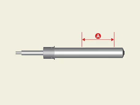
| 1.
|
Fully extend the piston rod.
|
| 2.
|
Drill a hole on the A section to remove gas from the cylinder.
|
The gas coming out is harmless, but be careful of debris that may fly when
drilling.
|
|
Rear Shock Absorber Reassembly
Tool Name / Number
|
Illustration
|
Description
|
Shock absorber lock nut remover.
09546 - 3X100
|
|
Used for removal or installing of rear shock absorber lock nut.
|
| 1.
|
Refer to the table below and reassemble the rear shock absorber assembly.
Reassembling Orders :
4 → 3 → 2 → 1
Number
|
Item
|
1
|
Insulator
|
2
|
Bumper rubber
|
3
|
Dust cover
|
4
|
Shock absorber assembly
|
|
| 2.
|
Install the rear shock absorber lock nut using the SST (09546 - 3X100).
|
Tightening torque :
19.6 - 24.5 N·m (2.0 - 2.5 kgf·m, 14.5 - 18.1 lb·ft)
|
|
Do not reuse the self locking nut.
|
|
| 3.
|
Install the insulator cap (A).
|
Other information:
Kia K4 (CL4) 2025-2026 Service Manual: Fuse/relay panel description
Located on the interior side of the fuse and relay panel covers, you will find a detailed label identifying the function, name, and amperage capacity of each fuse and relay for your Kia K4. This information is essential for troubleshooting electrical systems efficiently.
TIP
While the fuse panel descriptions provided in this manual are accurate as of the printing date, please be aware that minor variations in configuration may occur depending on the specific trim level, production date, and optional equipment fitted to your Kia K4.