Contents:
Rear Assist Arm Components and Components Location
| Component and Component Location |
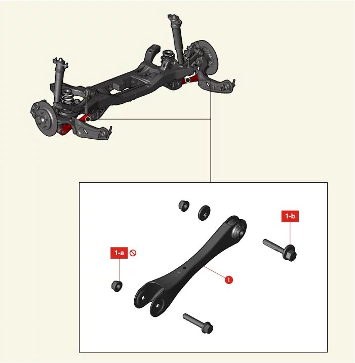
1. Rear Assist Arm
1-a. 63.7 - 73.5 N·m
(6.5 - 7.5
kgf·m, 47.0 - 54.2 lb·ft) + 175 - 185°
1-b. 127.5 - 137.3 N·m (13.0 - 14.0 kgf·m, 94.0 - 101.3
lb·ft)
|
|
Rear Assist Arm Removal and Installation
| 1.
|
Remove the rear wheel and tires.
(Refer to Wheel and Tire - "Wheel")
|
| 2.
|
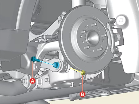
Remove the rear assist arm bolt (A) and nut (B).
|
Tightening torque :
63.7 - 73.5 N·m (6.5 - 7.5 kgf·m, 47.0 - 54.2 lb·ft) + 175 - 185°
|
|
•
|
Do not reuse the bolt and nut.
|
|
•
|
Install the transmission jack and lift up the parts to prevent
the bolts and nuts from
damage when installing or removing.
|
|
•
|
Mark and remove all bolt, nut and plate to prevent incorrectly
positioned installation.
|
|
|
Fix the bolt and remove or install the nut.
|
|
| 3.
|
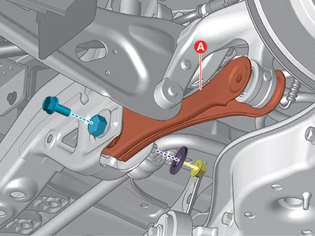
Remove the rear assist arm (A) after removing the bolt, nut, and plate.
|
Tightening torque :
127.5 - 137.3 N·m (13.0 - 14.0 kgf·m, 94.0 - 101.3 lb·ft)
|
|
•
|
Install the transmission jack and lift up the parts to prevent
the bolts and nuts from
damage when installing or removing.
|
|
•
|
Mark and remove all bolt, nut and plate to prevent incorrectly
positioned installation.
|
|
|
Fix the bolt and remove or install the nut.
|
|
| 1.
|
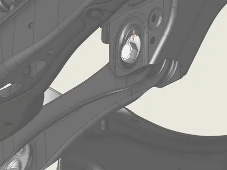
Install in reverse order of removal.
|
•
|
Align the center of the plate scale with the guideline when
installing bolt and nut.
|
|
•
|
Install to the specified torque.
|
|
|
| 2.
|
Check the alignment.
(Refer to Alignment - "Repair Procedures")
|
Rear Assist Arm Inspection
| 1.
|
Check the bushing for wear and aging.
|
| 2.
|
Check the rear assist arm for bent or damage.
|
Rear Coil Spring Components and Components Location
| Component and Component Location |
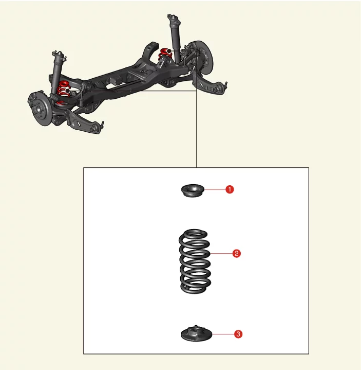
1. Rear Coil Spring Upper Pad
2. Rear Coil
Spring
3. Rear Coil Spring Lower Pad
|
|
Rear Coil Spring Removal and Installation
| 1.
|
Remove the rear wheel and tires.
(Refer to Wheel and Tire - "Wheel")
|
| 2.
|
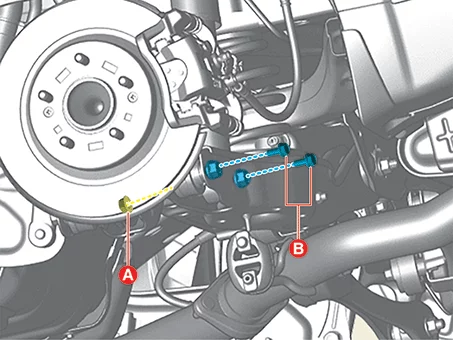
Remove the rear lower arm nut (A) and bolts (B).
|
Tightening torque :
44.1 - 53.9 N·m (4.5 - 5.5 kgf·m, 32.5 - 39.8 lb·ft) + 355 - 365°
|
|
•
|
Do not reuse the bolt and nut.
|
|
•
|
Install the transmission jack and lift up the parts to prevent
the bolts and nuts from
damage when installing or removing.
|
|
•
|
Mark and remove all bolts and nuts to prevent incorrectly
positioned installation.
|
|
|
Fix the bolt and remove or install the nut.
|
|
| 3.
|
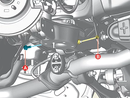
Remove the rear stabilizer bar link bolt (A) and nut (B).
|
Tightening torque :
58.8 - 68.6 N·m (6.0 - 7.0 kgf·m, 43.4 - 50.6 lb·ft)
|
|
•
|
Install the transmission jack and lift up the parts to prevent
the bolts and nuts from
damage when installing or removing.
|
|
•
|
Mark and remove all bolts and nuts to prevent incorrectly
positioned installation.
|
|
|
Fix the bolt and remove or install the nut.
|
|
| 4.
|
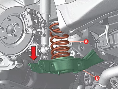
Lower the rear lower arm (B) in the direction of the arrow, then remove the rear coil spring
(A).
|
| 1.
|
Install in the reverse order of removal.
|
•
|
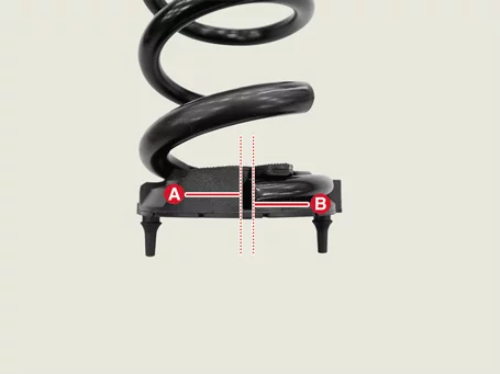
When installing the rear coil spring, mount it so that the
surface (A) of the lower pad
of the spring and the end of the spring (B) contact as much as
possible.
|
Maximum
allowable gap : 3 mm (0.11 in.)
|
|
|
•
|
Install to the specified torque.
|
|
|
| 2.
|
Check the alignment.
(Refer to Alignment - "Repair Procedures")
|
Rear Coil Spring Inspection
| 1.
|
Check the coil spring for cracks or deformation.
|
| 2.
|
Check the coil spring pad for damage and deformation.
|
Rear Crossmember Components and Components Location
| Component and Component Location |
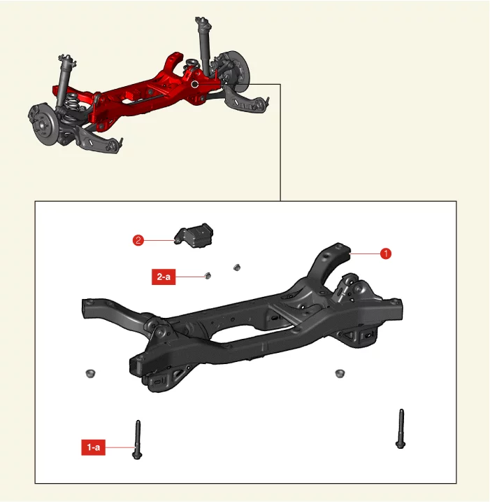
1. Rear Crossmember
1-a. 176.5 - 196.1 N·m
(18.0 -
20.0 kgf·m, 130.2 - 144.7 lb·ft)
|
2. Rear Crossmember Dynamic Damper
2-a.
44.1 - 53.9
N·m (4.5 - 5.5 kgf·m, 32.5 - 39.8 lb·ft)
|
Rear Crossmember Removal and Installation
|
•
|
This video was created using 3D graphics to help understand the vehicle
maintenance manual.
|
|
•
|
There may be some differences from actual vehicles.
|
|
•
|
The location and repair procedures of the parts may vary depending on vehicle
model, model year,
region, and specifications.
|
|
•
|
Check the KDS Guide for detailed information on how to use the KDS.
|
|
•
|
Check the manual for detailed maintenance procedures.
|
|
•
|
Unauthorized reproduction, distribution, or sharing of this video is
prohibited.
|
|
Rear Crossmember Removal
(Click to play)

Video: Rear Crossmember Removal
|
If a transmission jack is used with a two-post lift, do not lift the vehicle too much. The
center gravity
of the vehicle may change and fall.
|
| 1.
|
Remove the center and rear muffler.
G 1.6 T-GDI GAMMA II (Refer to Engine Mechanical System -
"Muffler")
G 2.0 MPI NU(ATKINSON) (Refer to Engine Mechanical System-
"Muffler")
|
| 2.
|
Remove the rear brake disc.
(Refer to Brake System - "Rear Brake Disc")
|
| 3.
|
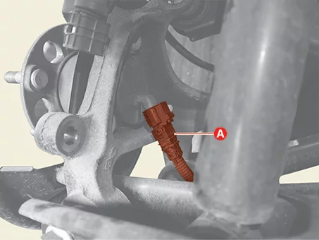
Disconnect the rear wheel speed sensor connector (A).
|
| 4.
|
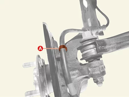
Remove the parking brake harness clip (A) from the dust cover.
|
| 5.
|
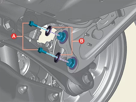
Remove the rear trailing arm bolts (A) and wahsers (B).
|
Tightening torque :
137.3 - 156.9 N·m (14.0 - 16.0 kgf·m, 101.3 - 115.7 lb·ft)
|
|
| 6.
|
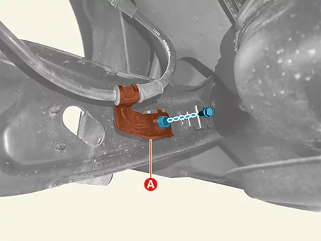
Separate the rear wheel speed sensor wiring bracket (A) after removing the bolt.
|
Tightening torque :
8.8 - 13.7 N·m (0.9 - 1.4 kgf·m, 6.5 - 10.1 lb·ft)
|
|
| 7.
|
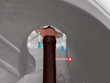
Separate the rear shock absorber (A) after removing the bolts.
|
Tightening torque :
58.8 - 73.5 N·m (6.0 - 7.5 kgf·m, 43.4 - 54.2 lb·ft)
|
|
•
|
Install the transmission jack and lift up the parts to prevent
the bolts and nuts from
damage when installing or removing.
|
|
•
|
Mark and remove all bolt to prevent incorrectly positioned
installation.
|
|
|
| 8.
|
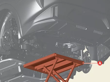
Support the rear crossmember with a suitable jack (A).
|
| 9.
|
Remove the rear crossmember bolts and nuts (A).
|
Tightening torque :
176.5 - 196.1 N·m (18.0 - 20.0 kgf·m, 130.2 - 144.7 lb·ft)
|
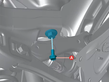
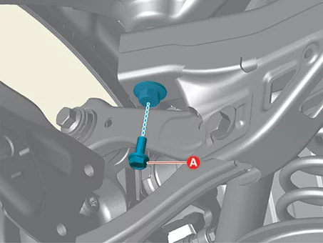
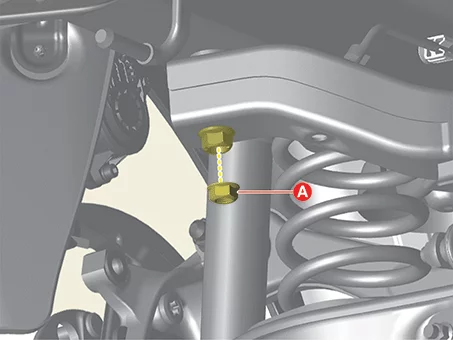
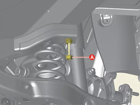
|
| 10.
|
Remove the rear crossmember by lowering the jack (A).
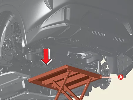
|
Check if there is no interfere with surrounding parts when removing or
installing the rear
crossmember.
|
|
| 11.
|
Remove the rear coil spring (A).
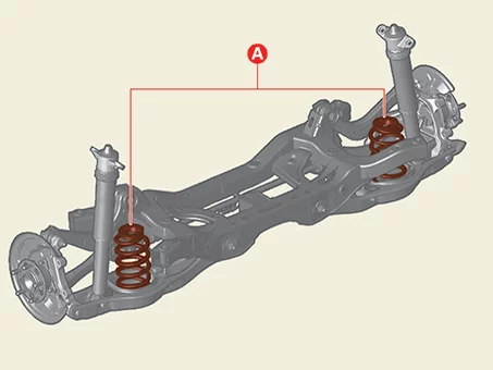
|
| 12.
|
Remove the rear shock absorber (A) after removing the bolts.
|
Tightening torque :
44.1 - 53.9 N·m (4.5 - 5.5 kgf·m, 32.5 - 39.8 lb·ft) + 355 - 365°
|
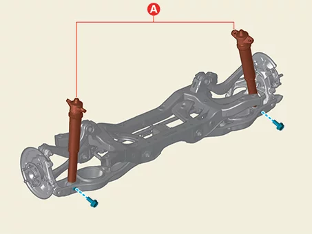
|
| 13.
|
Remove the rear upper arm (A) bolt, nut and washer.
|
Tightening torque :
44.1 - 53.9 N·m (4.5 - 5.5 kgf·m, 32.5 - 39.8 lb·ft) + 175 - 185°
|
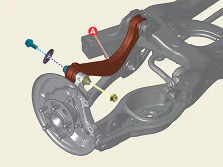
|
Do not reuse the bolt and nut.
|
|
| 14.
|
Remove the rear assist arm (A) bolt and nut.
|
Tightening torque :
63.7 - 73.5 N·m (6.5 - 7.5 kgf·m, 47.0 - 54.2 lb·ft) + 175 - 185°
|
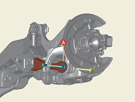
|
Do not reuse the bolt and nut.
|
|
| 15.
|
Remove the rear lower arm (A) bolt and nut.
|
Tightening torque :
44.1 - 53.9 N·m (4.5 - 5.5 kgf·m, 32.5 - 39.8 lb·ft) + 355 - 365°
|
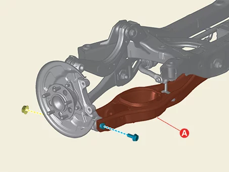
|
Do not reuse the bolt and nut.
|
|
| 16.
|
Remove the rear axle assembly (A).
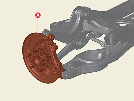
|
| 17.
|
Remove the rear upper arm (A) after removing the bolts.
|
Tightening torque :
63.7 - 73.5 N·m (6.5 - 7.5 kgf·m, 47.0 - 54.2 lb·ft) + 355 - 365°
|
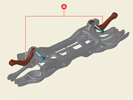
|
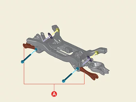
| 18.
|
Remove the rear assist arm (A) after removing the bolts, nuts and plates.
|
Tightening torque :
127.5 - 137.3 N·m (13.0 - 14.0 kgf·m, 94.0 - 101.3 lb·ft)
|
|
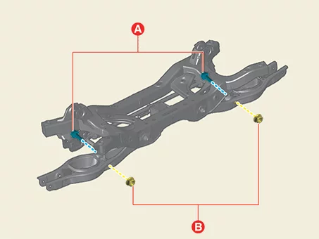
| 19.
|
Remove the rear stabilizer bar link bolts (A) and nuts (B).
|
Tightening torque :
58.8 - 68.6 N·m (6.0 - 7.0 kgf·m, 43.4 - 50.6 lb·ft)
|
|
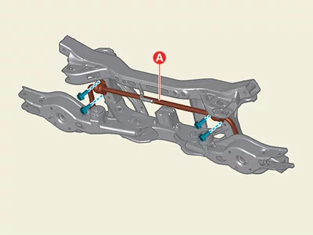
| 20.
|
Remove the rear stabilizer bar (A) after removing the bolts.
|
Tightening torque :
44.1 - 53.9 N·m (4.5 - 5.5 kgf·m, 32.5 - 39.8 lb·ft)
|
|
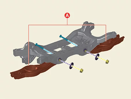
| 21.
|
Remove the rear lower arm (A) after removing the bolts, nuts and plates.
|
Tightening torque :
127.5 - 137.3 N·m (13.0 - 14.0 kgf·m, 94.0 - 101.3 lb·ft)
|
|
| 22.
|
Remove the dynamic damper (A) after removing the nuts.
|
Tightening torque :
44.1 - 53.9 N·m (4.5 - 5.5 kgf·m, 32.5 - 39.8 lb·ft)
|
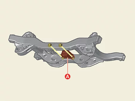
|
| 1.
|
Install in reverse order of removal.
|
Align the center of the plate scale with the guideline when installing bolt and
nut.
[Rear Assist Arm]
[Rear Lower Arm]
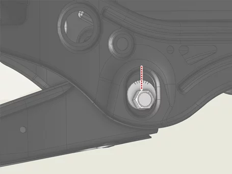
|
|
| 2.
|
Check the alignment.
(Refer to Alignment - "Repair Procedures")
|
Rear Crossmember Inspection
| 1.
|
Check the bushing for aging or wearing.
|
| 2.
|
Check all bolts and nuts.
|
Rear Lower Arm Components and Components Location
| Component and Component Location |
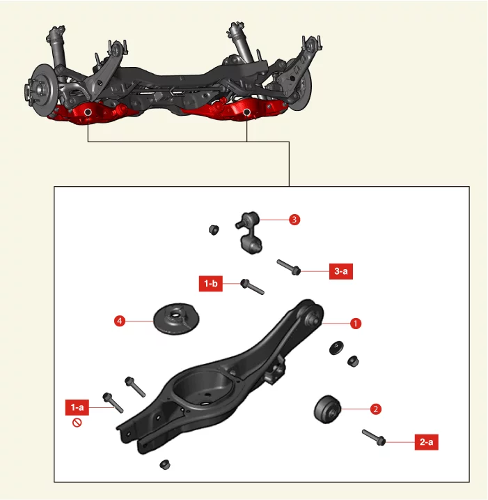
1. Rear Lower Arm
1-a. 44.1 - 53.9 N·m (4.5
- 5.5
kgf·m, 32.5 - 39.8 lb·ft) + 355 - 365°
1-b. 127.5 - 137.3 N·m (13.0 - 14.0 kgf·m, 94.0 - 101.3
lb·ft)
|
2. Rear Lower Arm Dynamic Damper
2-a. 44.1
- 53.9
N·m (4.5 - 5.5 kgf·m, 32.5 - 39.8 lb·ft)
3. Rear Stabilizer Bar Link
3-a. 58.8 - 68.6 N·m (6.0
- 7.0
kgf·m, 43.4 - 50.6 lb·ft)
4. Rear Coil Spring Lower Pad
|
Rear Lower Arm Removal and Installation
| 1.
|
Remove the rear coil spring.
(Refer to Rear Suspension System - "Rear Coil Spring")
|
| 2.
|
Remove the rear lower arm dynamic damper (A) after removing the bolt.
|
Tightening torque :
44.1 - 53.9 N·m (4.5 - 5.5 kgf·m, 32.5 - 39.8 lb·ft)
|
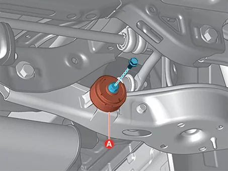
|
| 3.
|
Remove the rear lower arm (A) after removing the bolt, nut, and plate.
|
Tightening torque :
127.5 - 137.3 N·m (13.0 - 14.0 kgf·m, 94.0 - 101.3 lb·ft)
|
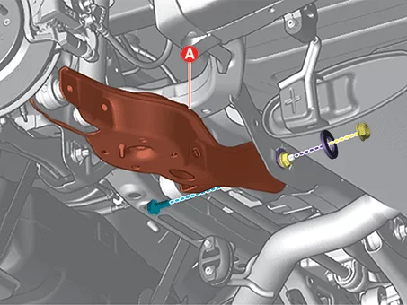
|
•
|
Install the transmission jack and lift up the parts to prevent
the bolts and nuts from
damage when installing or removing.
|
|
•
|
Mark and remove all bolt, nut and plate to prevent incorrectly
positioned installation.
|
|
|
Fix the bolt and remove or install the nut.
|
|
| 4.
|
Remove the rear coil spring lower pad (A) from the rear lower arm.
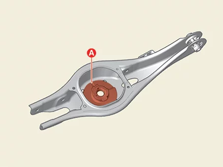
|
| 1.
|
Install in reverse order of removal.
|
•
|
Align the center of the plate scale with the guideline when
installing bolt and nut.
|
|
•
|
Install to the specified torque.
|
|
|
| 2.
|
Check the alignment.
(Refer to Alignment - "Repair Procedures")
|
Rear Lower Arm Inspection
| 1.
|
Check the bushing for wear and aging.
|
| 2.
|
Check the rear lower arm for bent or damage.
|
| 3.
|
Check all bolts and nuts.
|
Rear Shock Absorber Components and Components Location
| Component and Component Location |
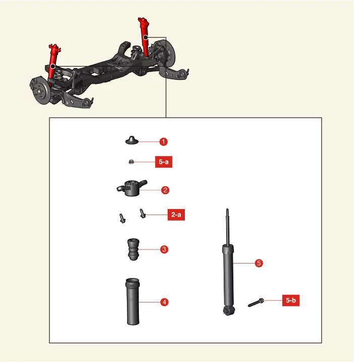
1. Insulator Cap
2. Insulator
2-a. 58.8
- 73.5
N·m (6.0 - 7.5 kgf·m, 43.4 - 54.2 lb·ft)
|
3. Bumper Rubber
4. Dust Cover
5. Shock
Absorber
Assembly
5-a. 19.6 - 24.5 N·m (2.0 - 2.5 kgf·m, 14.5 - 18.1 lb·ft)
5-b. 44.1 - 53.9 N·m (4.5 -
5.5
kgf·m, 32.5 - 39.8 lb·ft) + 355 - 365°
|
Rear Shock Absorber Removal and Installation
| 1.
|
Remove the rear wheel and tires.
(Refer to Wheel and Tire - "Wheel")
|
| 2.
|
Remove the rear shock absorber lower bolt (A).
|
Tightening torque :
44.1 - 53.9 N·m (4.5 - 5.5 kgf·m, 32.5 - 39.8 lb·ft) + 355 - 365°
|
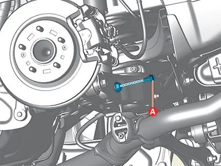
|
•
|
Install the transmission jack and lift up the parts to prevent
the bolts and nuts from
damage when installing or removing.
|
|
•
|
Mark and remove all bolt to prevent incorrectly positioned
installation.
|
|
|
| 3.
|
Remove the rear shock absorber (A) after removing the bolts.
|
Tightening torque :
58.8 - 73.5 N·m (6.0 - 7.5 kgf·m, 43.4 - 54.2 lb·ft)
|
|
| 1.
|
Install in reverse order of removal.
|
Install to the specified torque.
|
|
Rear Shock Absorber Disassembly
Tool Name / Number
|
Illustration
|
Description
|
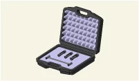
Shock absorber lock nut remover.
09546 - 3X100
|
|
Used for removal or installing of rear shock absorber lock nut.
|
| 1.
|
Remove the rear shock absorber.
(Refer to Rear Suspension System - "Rear Shock
Absorber")
|
| 2.
|
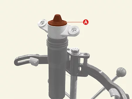
Remove the insulator cap (A).
|
| 3.
|
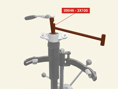
Remove the self locking nut using the SST (09546 - 3X100).
|
Tightening torque :
19.6 - 24.5 N·m (2.0 - 2.5 kgf·m, 14.5 - 18.1 lb·ft)
|
|
Do not reuse the lock nut.
|
|
| 4.
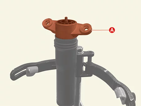
|
Remove the insulator (A).
|
| 5.
|
Remove the dust cover (A).
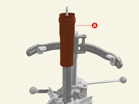
|
| 6.
|
Remove the bumper stopper (A).
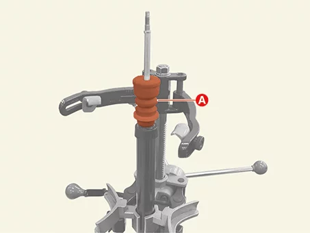
|
| 7.
|
Refer to the table below and disassemble the rear shock absorber assembly.
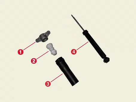
Disassembling Orders :
1 → 2 → 3 → 4
Number
|
Item
|
1
|
Insulator
|
2
|
Bumper rubber
|
3
|
Dust cover
|
4
|
Shock absorber assembly
|
|
Rear Shock Absorber Inspection
| 1.
|
Check the rubber parts for damage or deterioration.
|
| 2.
|
Check all bolts and nuts.
|
| 3.
|
Repeat compression and tension of the rear shock absorber rod (A) to check for abnormal
resistance or
noise between operations.
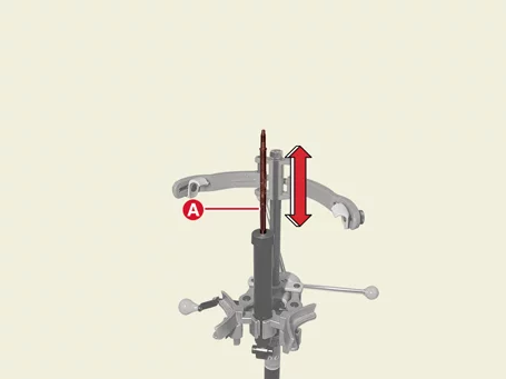
|
| 1.
|
Fully extend the piston rod.
|
| 2.
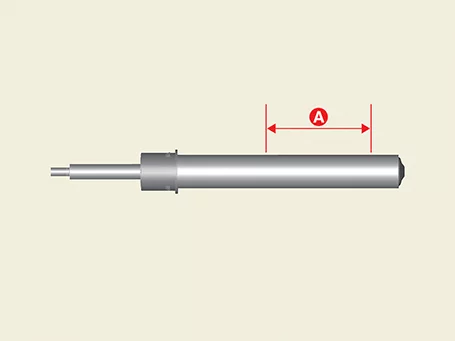
|
Drill a hole on the A section to remove gas from the cylinder.
|
The gas coming out is harmless, but be careful of debris that may fly when
drilling.
|
|
Rear Shock Absorber Reassembly
Tool Name / Number
|
Illustration
|
Description
|
Shock absorber lock nut remover.
09546 - 3X100
|
|
Used for removal or installing of rear shock absorber lock nut.
|
| 1.
|
Refer to the table below and reassemble the rear shock absorber assembly.
Reassembling Orders :
4 → 3 → 2 → 1
Number
|
Item
|
1
|
Insulator
|
2
|
Bumper rubber
|
3
|
Dust cover
|
4
|
Shock absorber assembly
|
|
| 2.
|
Install the rear shock absorber lock nut using the SST (09546 - 3X100).
|
Tightening torque :
19.6 - 24.5 N·m (2.0 - 2.5 kgf·m, 14.5 - 18.1 lb·ft)
|
|
Do not reuse the self locking nut.
|
|
| 3.
|
Install the insulator cap (A).
|
Rear Stabilizer Bar Components and Components Location
| Component and Component Location |
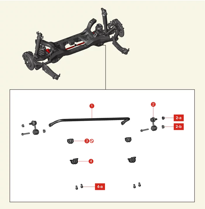
1. Rear Stabilizer Bar
2. Rear
Stabilizer Bar Link
2-a. 58.8 - 78.5 N·m (6.0 - 8.0 kgf·m, 43.4 - 57.9 lb·ft)
2-b. 58.8 - 68.6
N·m (6.0
- 7.0 kgf·m, 43.4 - 50.6 lb·ft)
|
3. Rear Stabilizer Bar Bushing
4. Rear
Stabilizer
Bar Bracket
4-a. 44.1 - 53.9 N·m (4.5 - 5.5 kgf·m, 32.5 - 39.8 lb·ft)
|
Rear Stabilizer Bar Removal and Installation
[Rear Stabilizer Bar Link]
| 1.
|
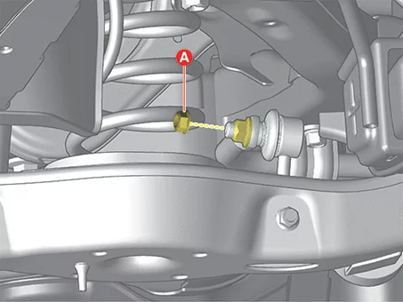
Remove the rear stabilizer bar link nut (A).
|
Tightening torque :
58.8 - 78.5 N·m (6.0 - 8.0 kgf·m, 43.4 - 57.9 lb·ft)
|
|
•
|
Fix the outer stud using a tool such as a wrench when
installing and removing the
stabilizer bar link nut.
|
|
•
|
Be careful not to damage the boot of the link.
|
|
•
|
Use a hand tool when removing or installing the rear stabilizer
bar link nut.
|
|
|
| 2.
|
Remove the rear stabilizer bar link after removing the bolt (A) and nut (B).
|
Tightening torque :
58.8 - 68.6 N·m (6.0 - 7.0 kgf·m, 43.4 - 50.6 lb·ft)
|
|
•
|
Install the transmission jack and lift up the parts to prevent
the bolts and nuts from
damage when installing or removing.
|
|
•
|
Mark and remove all bolts and nuts to prevent incorrectly
positioned installation.
|
|
|
Fix the bolt and remove or install the nut.
|
|
[Rear Stabilizer Bar]
| 1.
|
Remove the rear stabilizer bar link nut (A).
|
Tightening torque :
58.8 - 78.5 N·m (6.0 - 8.0 kgf·m, 43.4 - 57.9 lb·ft)
|
|
•
|
Fix the outer stud using a tool such as a wrench when
installing and removing the
stabilizer bar link nut.
|
|
•
|
Be careful not to damage the boot of the link.
|
|
•
|
Use a hand tool when removing or installing the rear stabilizer
bar link nut.
|
|
|
| 2.
|
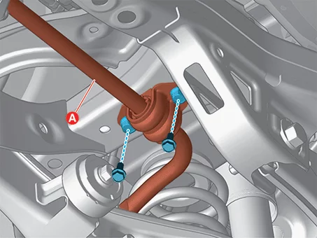
Remove the stabilizer bar (A) after removing the bolts.
|
Tightening torque :
44.1 - 53.9 N·m (4.5 - 5.5 kgf·m, 32.5 - 39.8 lb·ft)
|
[LH]
[RH]
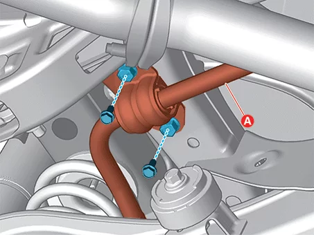
|
| 3.
|
Remove the stabilizer bar bracket (A) using a flat-head screw driver.
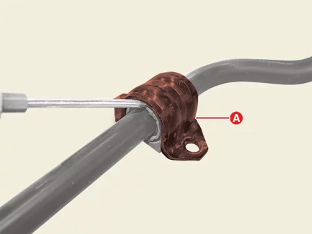
|
Do not reuse the rear stabilizer bar bracket (A) if it is deformed.
|
|
| 4.
|
Remove the stabilizer bar bushing (A) using a flat-head screw driver.
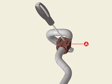
|
Do not reuse the rear stabilizer bar bushing (A).
|
|
When replacing the rear stabilizer bar bushing (A), lubricate it for better
installation.
|
|
| 1.
|
Install in reverse order of removal.
|
Install to the specified torque.
|
|
| 2.
|
Check the alignment. [After replacing the rear stabilizer
bar]
(Refer to Alignment - "Repair Procedures")
|
Rear Stabilizer Bar Inspection
| 1.
|
Check the rear stabilizer bar bushing for damage.
|
| 2.
|
Check the rear stabilizer bar link ball joint for damage.
|
| 3.
|
Check all bolts and nuts.
|
Rear Upper Arm Components and Components Location
| Component and Component Location |
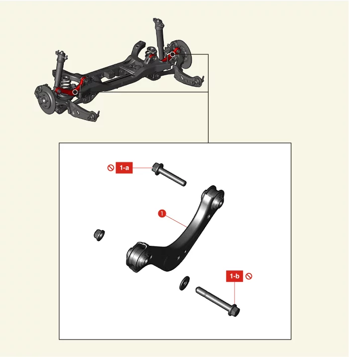
1. Rear Upper Arm
1-a. 63.7 - 73.5 N·m (6.5
- 7.5
kgf·m, 47.0 - 54.2 lb·ft) + 355 - 365°
1-b. 44.1 - 53.9 N·m (4.5 - 5.5 kgf·m, 32.5 - 39.8 lb·ft)
+ 175 -
185°
|
|
Rear Upper Arm Removal and Installation
| 1.
|
Remove the rear wheel and tires.
(Refer to Wheel and Tire - "Wheel")
|
| 2.
|
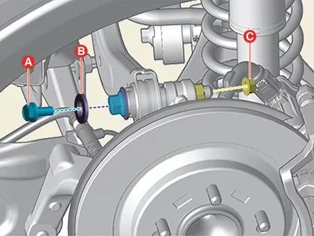
Remove the rear upper arm bolt (A), washer (B), and nut (C).
|
Tightening torque :
44.1 - 53.9 N·m (4.5 - 5.5 kgf·m, 32.5 - 39.8 lb·ft) + 175 - 185°
|
|
•
|
Do not reuse the bolt and nut.
|
|
•
|
Install the transmission jack and lift up the parts to prevent
the bolts and nuts from
damage when installing or removing.
|
|
•
|
Mark and remove all bolt to prevent incorrectly positioned
installation.
|
|
|
Fix the bolt and remove or install the nut.
|
|
| 3.
|
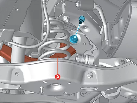
Remove the rear upper arm (A) after removing the bolt.
|
Tightening torque :
63.7 - 73.5 N·m (6.5 - 7.5 kgf·m, 47.0 - 54.2 lb·ft) + 355 - 365°
|
|
•
|
Install the transmission jack and lift up the parts to prevent
the bolt from damage when
installing or removing.
|
|
|
| 1.
|
Install in reverse order of removal.
|
Install to the specified torque.
|
|
| 2.
|
Check the alignment.
(Refer to Alignment - "Repair Procedures")
|
Rear Upper Arm Inspection
| 1.
|
Check the bushing for wear and aging.
|
| 2.
|
Check the rear upper arm for bent or damage.
|
| 3.
|
Check all bolts and nuts.
|
Trailing Arm Components and Components Location
| Component and Component Location |
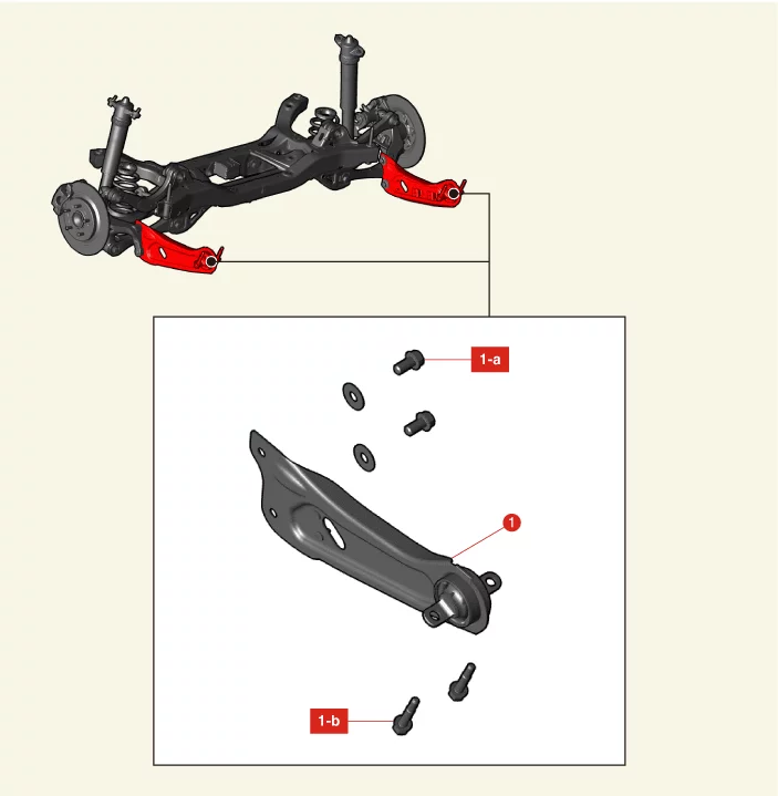
1. Trailing Arm
1-a. 137.3 - 156.9 N·m
(14.0 -
16.0 kgf·m, 101.3 - 115.7 lb·ft)
1-b. 98.1 - 117.7 N·m (10.0 - 12.0 kgf·m, 72.3 - 86.8 lb·ft)
|
|
Trailing Arm Removal and Installation
| 1.
|
Remove the rear wheel and tires.
(Refer to Wheel and Tire - "Wheel")
|
| 2.
|
Separate the rear wheel speed sensor wiring bracket (A) after removing the bolt.
|
Tightening torque :
8.8 - 13.7 N·m (0.9 - 1.4 kgf·m, 6.5 - 10.1 lb·ft)
|
|
| 3.
|
Remove the rear trailing arm bolts (A) and wahsers (B).
|
Tightening torque :
137.3 - 156.9 N·m (14.0 - 16.0 kgf·m, 101.3 - 115.7 lb·ft)
|
|
| 4.
|
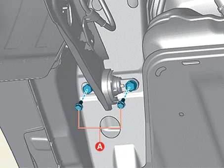
Remove the trailing arm after removing the bolts (A).
|
Tightening torque :
98.1 - 117.7 N·m (10.0 - 12.0 kgf·m, 72.3 - 86.8 lb·ft)
|
|
| 1.
|
Install in reverse order of removal.
|
Install to the specified torque.
|
|
| 2.
|
Check the alignment.
(Refer to Alignment - "Repair Procedures")
|
Trailing Arm Inspection
| 1.
|
Check the bushing for wear and aging.
|
| 2.
|
Check the trailing arm for bent or damage.
|
| 3.
|
Check all bolts and nuts.
|
Other information:
Kia K4 (CL4) 2025-2026 Service Manual: Lane Keeping Assist (LKA)
When operating your Kia K4 at speeds above a certain threshold, the Lane Keeping Assist (LKA) system actively monitors road lane markings and edges. Designed to enhance your driving experience, Lane Keeping Assist can provide proactive steering assistance to help prevent your Kia K4 from unintentionally drifting out of its lane. Furthermore, the system is engineered to provide an alert if it detects that the vehicle is departing from its lane without the driver engaging the turn signal.
Kia K4 (CL4) 2025-2026 Service Manual: Seat belt restraint system
To ensure maximum protection, occupants must wear their seat belts whenever the Kia K4 is in motion:
The shoulder belt should be adjusted to rest midway over the shoulder and across the collarbone, never against the neck.
For safety reasons, never allow children to ride in the front passenger seat. Please refer to the "Child Restraint System (CRS)" section of your Kia K4 owner's manual for detailed guidance on appropriate child seating.