Contents:
12V Lithium Auxiliary Battery Removal and Installation - 4DR
|
The indication below represents the location of a clip or fastener.

|
12V Lithium Auxiliary Battery
| 1.
|
Remove the luggage side trim. [Passenger's Side]
(Refer to Luggage Trim - "Luggage Side Trim")
|
| 2.
|
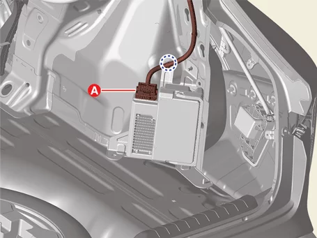
Disconnect the connector (A).
|
| 3.
|
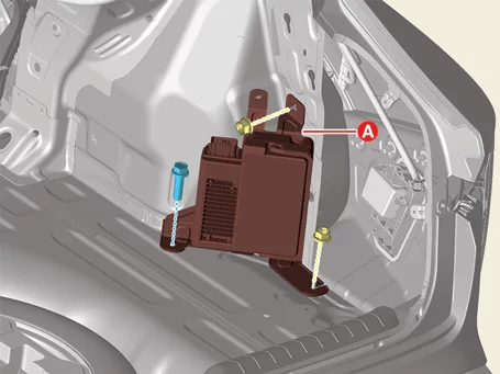
Remove the battery (A) after removing the bolt and nuts.
|
Tightening torque:
9.8 - 12.7 N·m (1.0 - 1.3 kgf·m, 7.2 - 9.4 lb·ft)
|
|
| 1.
|
Install in the reverse order of removal.
|
12V Lithium Auxiliary Battery Removal and Installation - 5DR
12V Lithium Auxiliary Battery
| 1.
|
Remove the front seat assembly. [Driver's Side]
(Refer to Front Seat - "Front Seat Assembly")
|
| 2.
|
Remove the floor console assembly.
(Refer to Floor Console - "Floor Console Assembly")
|
| 3.
|
Remove the cowl side trim. [Driver's Side]
(Refer to Interior Trim - "Cowl Side Trim")
|
| 4.
|
Remove the lower center pillar trim. [Driver's Side]
(Refer to Interior Trim - "Center Pillar Trim")
|
| 5.
|
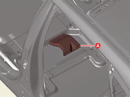
Remove the air vent duct (A).
|
| 6.
|
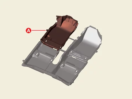
Separate the floor carpet assembly (A).
|
| 7.
|
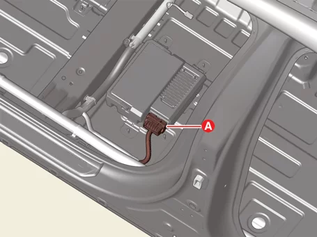
Disconnect the battery connector (A).
|
| 8.
|
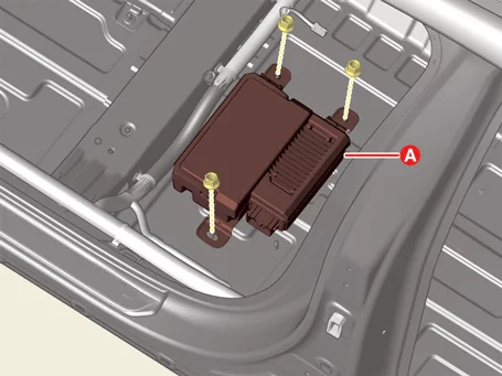
Remove the battery (A) after removing the nuts.
|
Tightening torque:
9.8 - 12.7 N·m (1.0 - 1.3 kgf·m, 7.2 - 9.4 lb·ft)
|
|
| 1.
|
Install in the reverse order of removal.
|
Body Domain Control Unit Description and Operation
| Description and Operation |
Body Domain Control Unit (BDC)
The body domain control unit is a unit that integrates functions such as a body control module (BCM), a smart
key
unit (SMK), a tire pressure monitoring system (TPMS), and an immobilizer.
| 1.
|
Body Control Module Functions
Burglar Alarm
|
Tailgate Burglar Alarm
|
Issues an alarm depending on the tailgate operation.
|
Panic Alarm
|
Generates warning sound and displays flasher lamp (horn & flasher) depending on
the panic
signal.
|
Security Lamp Control
|
Controls security lamp in vehicle alert status.
|
External Lamp
|
Tail Lamp
|
Turns on / off the tail lamp automatically. It also turns
off the tail lamp
automatically when the driver forgot to turn off the lamp switch.
|
Auto Light
|
Turns on/off the tail lamp and head lamp automatically depending on whether it is
day or night when
the headlamp switch is placed at Auto.
|
Welcome Light
|
The welcome light function turns on the headlamp and tail lamp for 15 seconds when
an unlock signal is
detected while vehicle door is locked.
|
Escort Function
|
Turns on the escort lamp when the power is turned off while the headlamp is on.
|
–
|
It turns on the headlamp and maintains the state for 20 minutes
if POWER is turned off
while the head lamp is on.
|
|
–
|
The head lamp remains on only for 30 seconds when the driver
seat door is opened and
closed during the 20 minute period.
|
|
–
|
The headlamp turns off when remote control lock button is
pressed twice while the head
lamp is on.
|
|
Headlamp (Low Beam / High Beam)
|
Controls high beam / low beam depending on the head lamp switch (multifunction
switch).
|
Daytime Driving Light Control
|
Controls the daytime driving light lamp depending on the conditions at the time of
vehicle start.
|
Telematics (MTS)
|
MTS Alarm Control
|
Controls the output of the door lock/unlock/remote
start/panic function in
response to the signal transmitted by the MTS unit
|
Front / Rear Parking Assist (PDW)
|
PDW Display
|
Receives a signal from parking assist sensor through LIN
communication and
displays it on the instrument cluster.
|
PDW Warning
|
Detects obstacles in front and rear sides using the ultrasonic sensor (PDW) in the
case of gear range
("R" or "D") and issues a warning if there is an obstacle.
|
Warning
|
Seat Belt Reminder and Indicator Lamp
|
Issues a warning if the seat belt is not fastened, and
prevents pattern
activation if the vehicle is driven while the seat belt is not fastened.
|
Key Reminder Warning
|
Issues a warning if the driver seat door is open while ACC is on.
|
Key Reminder Warning
|
Issues a warning if the driver seat door is open while POWER is on.
|
Sunroof Open Warning
|
Alarm output function when getting out of the car by removing the key while the
sunroof is open
|
Wiper and Washer
|
Wiper (Low / High / Mist / Auto)
|
Controls wiper operating power and fail-safe circuit.
|
Wiper
|
Control the washer interlocking wiper.
|
|
| 2.
|
Smart Key Unit Functions
SMK
|
Door Lock and Unlock
|
Locks/Unlocks the door based on the door unlock signal and
the signal from
push buttons on the driver's / passenger's side outside handles.
|
SMK Welcome Light
|
Controls door mirror and puddle lamp after smart key authentication when the driver
with smart key
approaches the vehicle.
|
Power Tailgate
|
When holding a smart key and staying in the rear bumper (in the LF antenna area) for
more than 3
seconds, the power tailgate opening function is performed.
|
SMK Warning
|
Key Reminder 1
|
When the driver attempts to lock the door, it checks if
there is a smart key
inside the vehicle and unlocks the door if there is one.
|
Key Reminder 2
|
Checks the door lock status for 0.5 seconds after the vehicle door is closed and
unlocks the door and
generates a warning sound using the external buzzer if the door is locked.
|
Door Lock Warning 1
|
Generates a warning sound with the external buzzer if the driver tries to leave the
vehicle while
POWER ON.
|
Door Lock Warning 2
|
Generates a warning sound with the external buzzer if the driver tries to lock the
door and leave the
vehicle while one or more doors are open.
|
Door Lock Warning 3
|
Searches for a smart key inside the vehicle when the driver tries to lock the door,
and issues a
warning and does not lock the door if there is a smart key inside.
|
Key Out Lamp Warning
|
If the vehicle moves at 3 km/h or less while POWER ON and the door is open, it
searches for the smart
key every 3 seconds and blinks the warning lamp if there is no smart key.
|
SMK RKE (Remote Keyless Entry)
|
Door Lock / Unlock
|
Locks/Unlocks the door based on the door unlock signal and the signal from push
buttons on the
driver's / passenger's side outside handles.
|
Panic
|
Performs vehicle panic and panic stop functions based on the panic button
signal.
|
Engine Start
|
Start stop button (SSB), immobilizer, start relay power control, SSB Lamp
Control.
|
|
| 3.
|
Tire Pressure Monitoring System (TPMS) Functions
Tire pressure monitoring system continuously monitors pressure and temperature inside the tire
in order
to warn the driver of the changes in tire pressure that may have influence on vehicle driving
conditions.
TPMS control module analyzes the data from the WE (Wheel Electronic) sensor attached inside each
wheel and
determines the tire conditions and generates a signal that is necessary for warning lamp
control.
|
| 4.
|
Identity Authentication Unit (IAU) Function
The IAU receives the encrypted digital key value from the smartphone, decrypts it, analyzes it,
and
delivers the authentication result to the BDC.
|
Body Domain Control Unit On Vehicle Inspection
| 1.
|
The Body Domain Control unit (BDC) can quickly diagnosed for problems with the KDS (Refer to
"DTC
guide").
| (1)
|
Self diagnosis : Inspect the Diagnostic Trouble Code (DTC) with the KDS.
(Refer to DTC guide when fault code is found.)
|
| (2)
|
S/W Management : Controlling other features including system option setting and
zero point
adjustment.
(S/W Management → BDC-BCM → Variant Coding)
(S/W Management → BDC-SMK → Smart Key Code Saving)
(S/W Management → BDC-TPMS → ID Writing)
(S/W Management → BDC-IAU → Status Information)
(S/W Management → BDC-IAU → Learning Mode)
(S/W Management → BDC-IAU → IAU Neutralization Mode)
(S/W Management → BDC-IAU → Activate Card Key Registration Mode)
|
|
Refer to the KDS screen for operating conditions and details
|
|
Body Domain Control Unit Removal and Installation
Body Domain Control Unit (BDC)
| 1.
|
Perform the order below with the KDS before removing the Body Domain Control unit (BDC).
(S/W Management → BDC-IAU → IAU Neutralization Mode)
|
Refer to the KDS screen for operating conditions and details.
|
|
| 2.
|
Remove the Connected Car Navigation Cockpit (ccNC).
(Refer to Infotainment System - "Connected Car Navigation
Cockpit
(ccNC)")
|
| 3.
|
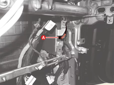
Disconnect the unit connector (A).
|
| 4.
|
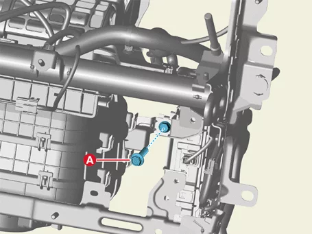
Remove the bolt (A).
|
Tightening torque :
6.6 - 9.9 N·m (0.67 - 1.01 kgf·m, 4.8 - 7.3 lb·ft, 58.2 - 87.7 lb·in)
|
|
| 5.
|
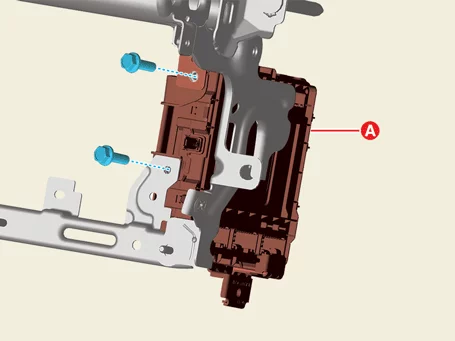
Remove the unit (A) after removing the bolts.
|
Tightening torque :
6.6 - 9.9 N·m (0.67 - 1.01 kgf·m, 4.8 - 7.3 lb·ft, 58.2 - 87.7 lb·in)
|
|
| 6.
|
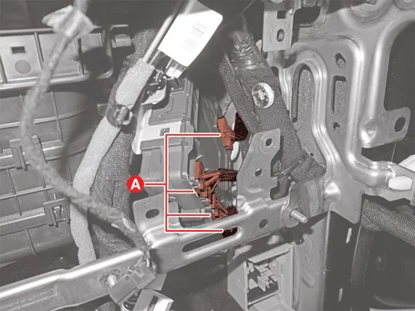
Disconnect the unit connectors (A).
|
| 1.
|
Install in the reverse order of removal.
|
| 2.
|
Perform the order below with the KDS when replacing the body domain control unit.
(S/W Management → BDC-BCM → Variant Coding)
(S/W Management → BDC-SMK → Smart Key Code Saving)
(S/W Management → BDC-TPMS → ID Writing)
(S/W Management → BDC-IAU → Learning Mode)
|
Refer to the KDS screen for operating conditions and details.
|
|
| 3.
|
Perform Over The Air (OTA) controller S/W update with KDS.
(Refer to Security & Vehicle Ignition System - "Over The
Air
(OTA)")
|
The system offers the following features:
|
–
|
Switching between off, IG ON and power by pushing the start button.
|
|
–
|
Controls external relays for ACC / IG1 / IG2 terminal switching and STARTER, without use of
mechanical IG
switch.
|
|
–
|
Indicating the vehicle status on cluster by displaying messages.
|
|
–
|
Immobilizer function by LF transponder communication between fob and button start switch.
|
|
–
|
Interface with Low Speed CAN vehicle communication network.
|
|
–
|
Interface with LIN vehicle communication network depending on platform.
|
System Main Function
|
•
|
Switching of ACC / IG1 / IG2 terminal.
|
|
•
|
Control of the STARTER relay based on communication with EMS ECU.
|
|
•
|
Management of the Immobilizer function.
|
|
•
|
Management of Button Start System warning function.
|
Wireless Communications
The electric signal is used to exchange information between vehicle and FOB key. For now, button start is
applied
with smart key FOB key together.
Smart key function is explained separately so refer to the corresponding system contents.
System Diagram
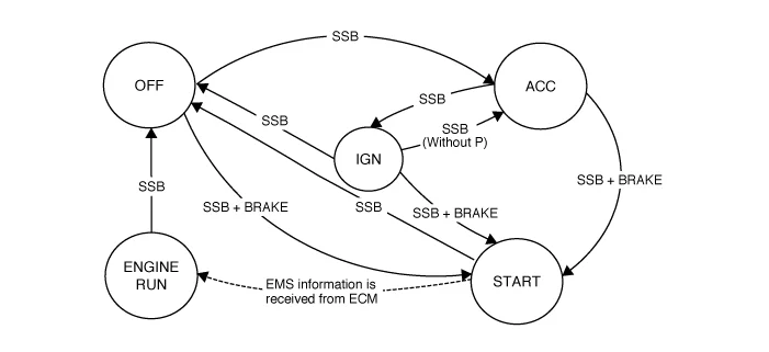
*SSB : Start / Stop Button
Schematic Diagram
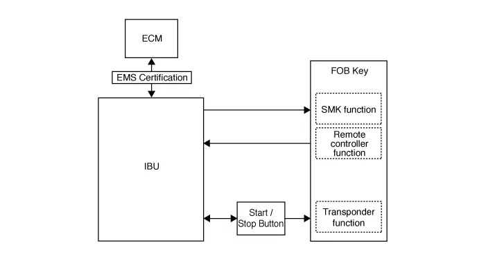
Body Domain Control Unit (BDC)
Body domain control unit function :
|
–
|
Start / Stop Button (SSB) control
|
|
–
|
Immobilizer communication (with ECM for releasing immobilizer)
|
|
–
|
Authentication server (Validity of Transponder and in case of Smart Key option Passive FOB
authentication)
|
|
–
|
System consistency monitoring
|
|
–
|
Control of display message / warning buzzer
|
Limp Home Mode
|
–
|
In case of no input signal for the brake switch (AT specification), the ACC mode shall cycle to
“START”
by pressing SSB for more than 10 seconds.
|
|
–
|
In case of problems with communication between EMS and CAN (the EMS state), the “START” state
cycles to
the “ENGINE RUN” based on rpm input.
|
|
–
|
In case that one out of two SSB input lines is disconnected, the electric power cycling is
available when
SSB is pressed twice within 10 seconds.
The buzzer rings when the button is pressed for the first time.
Electric power cycling is available and buzzer stops when the button is pressed twice within 10
seconds.
|
Terminal and Starter Relay
Relay is used to switch the terminal ACC / IG1 / IG2.
Normally-open relay is operated by smart key unit.
One relay coil is connected to output terminal of IBU.
| 1.
|
Remove the Start / Stop Button (SSB).
(Refer to Floor Console - "Floor Console Assembly")
|
| 1.
|
Install in the reverse order of removal.
|
Central Communication Unit (CCU) On Vehicle Inspection
| 1.
|
The central communication unit (CCU) can be quickly diagnosed for problems with the KDS. (Refer
to "DTC
guide")
| (1)
|
Self diagnosis : Inspect the Diagnostic Trouble Code (DTC) with the KDS.
(Refer to DTC guide when fault code is found)
|
| (2)
|
S/W Management : Controlling other features including system option setting and
zero point
adjustment.
(S/W Management → Central Communication Unit (CCNF) → Variant Coding)
(S/W Management → Central Communication Unit (CCNF) → OTA Initialization)
|
|
Refer to the KDS screen for operating conditions and details.
|
|
Central Communication Unit (CCU) Removal and Installation
Central Communication Unit (CCU)
| 1.
|
Remove the crash pad lower panel.
(Refer to Crash Pad - "Crash Pad Panel")
|
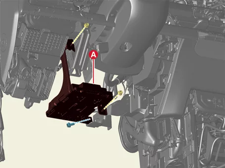
| 2.
|
Remove the unit (A) after removing the bolt and nuts.
|
Tightening torque :
6.9 - 10.8 N·m (0.7 - 1.1 kgf·m, 5.1 - 8.0 lb·ft)
|
|
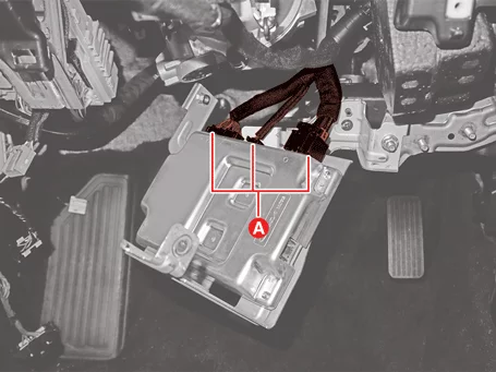
| 3.
|
Disconnect the unit connectors (A).
|
| 1.
|
Install in the reverse order of removal.
|
| 2.
|
Perform the order below with the KDS when replacing the Central Communication Unit (CCU).
(S/W Management → Central Communication Unit (CCNF) → Variant Coding)
|
Refer to the KDS screen for operating conditions and details.
|
|
| 3.
|
Perform Over The Air (OTA) controller S/W update with KDS.
(Refer to Security & Vehicle Ignition System - "Over The
Air
(OTA)")
|
Data Connectivity Unit (DCU) On Vehicle Inspection
| 1.
|
The Data Connectivity Unit (DCU) can be quickly diagnosed for problems with the KDS. (Refer to
"DTC
guide")
| (1)
|
Self diagnosis : Inspect the Diagnostic Trouble Code (DTC) with the KDS.
(Refer to DTC guide when fault code is found)
|
|
Refer to the KDS screen for operating conditions and details.
|
|
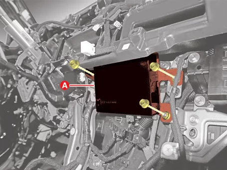
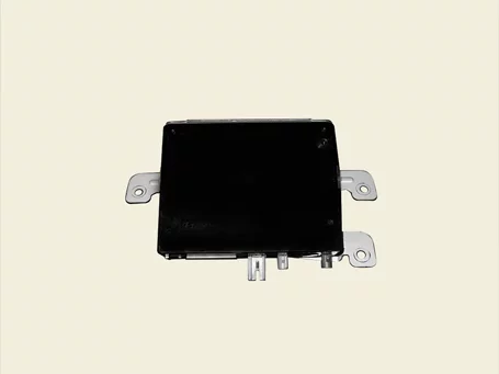
Data Connectivity Unit (DCU) Removal and Installation
Data Connectivity Unit (DCU)
| 1.
|
Remove the crash pad center panel.
(Refer to Crash Pad - "Crash Pad Panel")
|
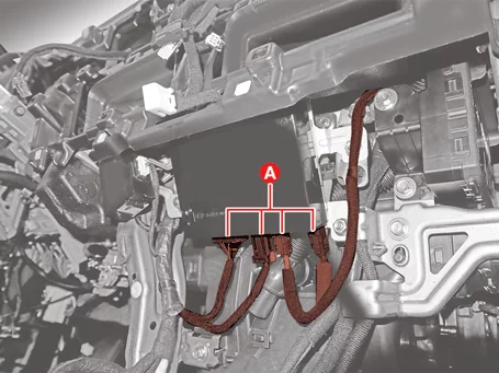
| 2.
|
Disconnect the unit connectors (A).
|
| 3.
|
Remove the unit (A) after removing the nuts.
|
Tightening torque :
7.8 - 11.8 N·m (0.8 - 1.2 kgf·m, 5.8 - 8.7 lb·ft)
|
|
| 1.
|
Install in the reverse order of removal.
|
| 2.
|
Perform the order below with the KDS when replacing the Data Connectivity Unit (DCU).
(S/W Management → DCU - Data Connectivity Unit → Software Information)
|
Refer to the KDS screen for operating conditions and details.
|
|
Digital Key System Description and Operation
Digital key system allows a driver to lock or unlock the vehicle doors with smartphone app or a NFC key card
without a smart key.
Main Features Of Digital Key System
|
•
|
A smartphone key can be issued from the digital key server and a NFC key card can be registered
through a
separate process.
|
|
•
|
The smartphone key can be registered through the ccNC screen of the vehicle by downloading the
app after
registering as a member on the Kia website.
|
|
•
|
The NFC card key can be registered through the ccNC screen of the vehicle after going through a
separate
authentication process.
(The separate authentication procedure is available with the digital key app or selecting “Card
key
registration mode activation” using the KDS.)
|
|
•
|
3 drivers can share a smartphone key at maximum but one NFC key card is provided.
|
|
•
|
When registering a smartphone key or an NFC card key, the user must possess the smart key, and
after
registration, door lock/unlock and start functions can be performed without carrying the smart
key.
|
|
•
|
If a smartphone is set up in the driver's profile (Profile 1, Profile 2, Guest) through the
ccNC screen,
the driver is automatically recognized when the door is unlocked and the personal preference
function (IMS,
ccNC, etc.) is executed.
|
|
•
|
Vehicle status information (mileage, fuel economy, battery level, etc.) can be checked on the
smartphone
app.
|
|
•
|
When you delete the smartphone key or NFC key card, you should have the smart key.
(Smartphone key or NFC key card is not required to carry to delete.)
|
Register a smartphone key or NFC key card using the registration process below.
Step
|
1. Sign up for membership
|
2. Install App & Login
|
3. Key Registration
|
4. Entry / Start
|
5. Key Sharing
|
Description
|
Create an account on the Kia membership website
|
Install the Kia Connect APP on your smartphone and login
|
Get in the car with the FOB key and register the smartphone and the NFC card key
|
NFC door lock/unlock, NFC vehicle start, remote control via APP
|
Digital key can be shared with others with the APP
|
|
Digital Key System On Vehicle Inspection
| 1.
|
The digital key system can quickly diagnosed for problems with the KDS. (Refer to "DTC guide")
| (1)
|
Self diagnosis : Inspect the Diagnostic Trouble Code (DTC) with the KDS.
(Refer to DTC guide when fault code is found)
|
| (2)
|
S/W Management : Controlling other features including system option setting
and zero point
adjustment.
(S/W Management → BDC-IAU → IAU Status Information)
(S/W Management → BDC-IAU → IAU - IBU Learning)
(S/W Management → BDC-IAU → Neutralization Mode)
|
|
Refer to the KDS screen for operating conditions and details.
|
|
Digital Key System NFC Key Card Registration
| NFC Key Card Registration Process |
|
•
|
The digital key system provides an NFC key card for emergency purposes, such as when a
smartphone cannot
be delivered directly, such as valet parking, or when the smartphone battery is off.
|
|
•
|
The card key must be registered in the vehicle for the first time after the vehicle is shipped
or the
first time after replacing the BDC to be used.
|
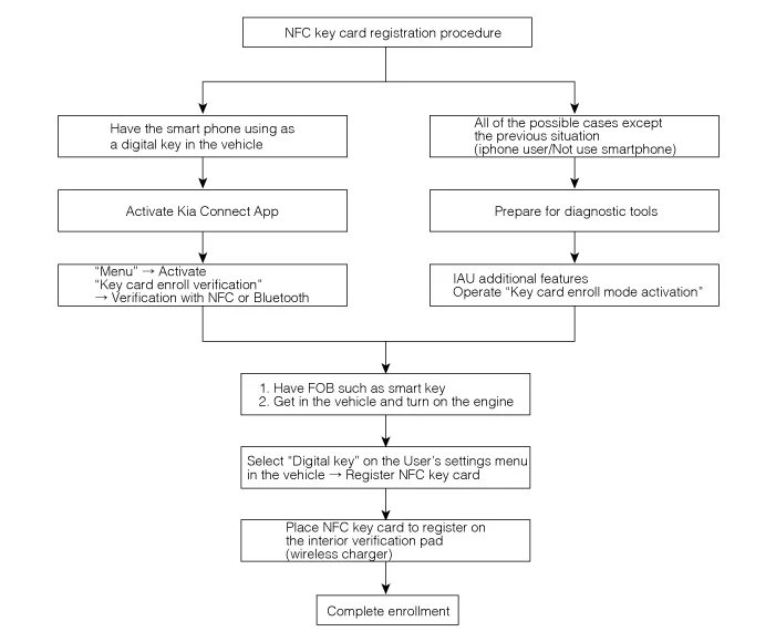
NFC Key Card Registration Process
You should follow the steps in the procedure below to register NFC key card.
| 1.
|
Make the vehicle enable to register NFC key card.
|
 It can be registered with KDS - S/W Management - "Card Key
Registration Mode Activation". |
|
 It also can be registered digital key app available in the
vehicle. |
|
|
| 2.
|
You should register the NFC key card on AVNT or the cluster within 5 minutes after getting in
the
vehicle.
|
•
|
When there is a previously enrolled NFC key card, the “Enroll”
button on the User’s
Settings menu is deactivated so press “Deletion” button to
delete the NFC key card and
register new one. (You should have your smart key to delete in
the vehicle)
|
|
•
|
A NFC key card can be registered and deleted repeatedly but if
you enroll a new NFC key
card, the previously enrolled key is not available.
|
|
•
|
When replacing the BDC-IAU (authentication controller), the
previously used NFC card key
cannot be used.
|
|
•
|
iPhone users and non-smartphone users can register the NFC card
key with KDS - S/W
Management - "Card Key Registration Mode Activation".
|
|
•
|
You should register the NFC key card in the vehicle within 5
minutes after proceeding
authentication process.
|
|
•
|
If the enrollment process fails to be completed within 5
minutes, you should retry after
re-processing the authentication.
|
|
|
NFC Key Card Registration With the KDS.
| 1.
|
Perform the order below with the KDS
(S/W Management → BDC-IAU → Card Key Registration Mode Activation)
|
Refer to the KDS screen for operating conditions and details.
|
|
| 2.
|
After placing the card key on the NFC wireless charger, register the card key on the Connected
Car
Navigation Cockpit (ccNC) screen.
|
•
|
You should get in the vehicle within 5 minutes and register the
key card After completing
“Key Card Enroll Mode” with the KDS.
|
|
•
|
When you register a NFC key card, the smart key should be in
the vehicle.
|
|
|
| 3.
|
Place the NFC key card that you want to register on the interior authentication pad (Wireless
charger) to
complete the process.
|
Digital Key System Digital Key System Inspection
Digital Key System Operation Verification
| 1.
|
When the digital key system failure occurs, the system operation should be confirmed as below.
| (1)
|
Checked the lock/unlock operation by touching the NFC antenna portion of the
door handle with a
smart phone or NFC card key.
|
| (2)
|
Check whether the start-up is working or not after placing your smart phone or
key card on the
wireless charger.
|
| (3)
|
Make sure confirm whether BLE lock or unlock are operable with the smart phone.
|
| (4)
|
If there is an abnormality in the operation of the digital key system, the
inspection is
performed according to the "Digital Key System A/S procedure" below.
|
|
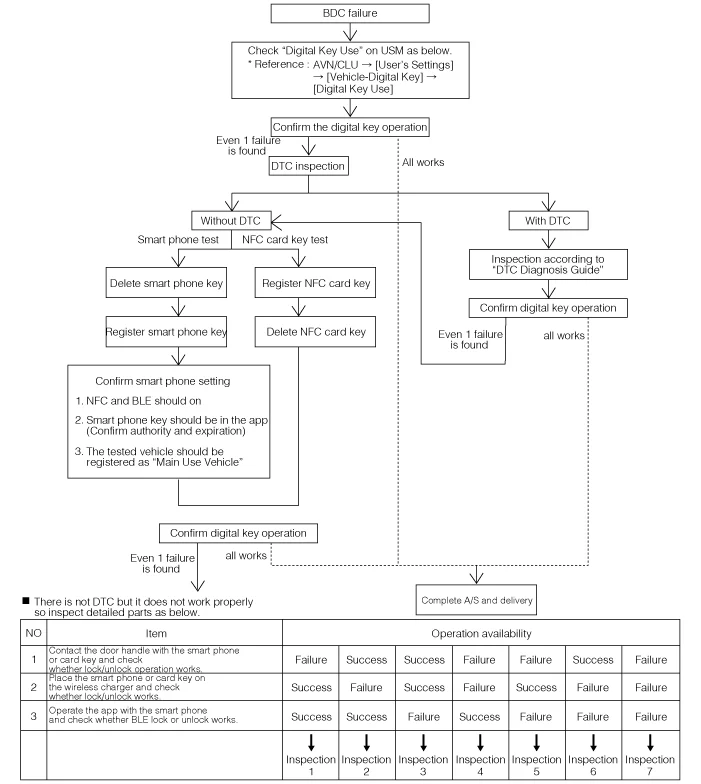
Digital Key System A/S Procedure
|
•
|
To inspect the digital key, vehicle owner’s smart phone or NFC card key is
required. If you do
not have both of those, you should register new NFC card key and complete the
test before delivering
the vehicle.
|
|
•
|
Once a new NFC key card is registered, the existing NFC key card is not
available.
|
|
Inspection 1 :
Check whether the door handles of driver’s seat and passenger’s seats work
properly. If the door
handle of the driver’s seat fails to operate, the handle should be checked after
replacing with
passenger’s seat door handle.
If it works properly, only the door handles of driver’s seat should be replaced
since it does not
have problem with wiring.
If both of those handles do not work, the door handles of driver’s seat and
passenger’s seat
should be replaced with a new handle to check whether it works properly.
If it performs normally, the handle should be replaced with a new one. However,
there is a
malfunction in the part, you assume (B166D00 driver’s seat door handle
malfunction) or (B166E00
passenger’s seat door handle malfunction) occurs and process inspections in
accordance with “DTC
Diagnosis Guide”.
|
|
Inspection 2 :
Check whether the tart-up with the digital key (smart phone or card key) after
replacing with new
wireless charger.
If it works properly, the vehicle can be delivered with the function on since
it does not have a
problem with wiring.
If it does not work even after replacing with a new product, the wireless
charger wiring should
be checked.
|
|
Inspection 3 :
After replacing with a new BLE module, check whether the digital key works.
If it does not work even after replacing with a new product, the wireless
charger wiring should
be checked.
If there is not a problem with wiring, we assume (B165A00 BLE module
malfunction), (B167F00 LIN
communication failure between IAU and BLE modules) occurs and process
inspections in accordance with
“DTC Diagnosis Guide”.
|
|
Inspection 4 :
Process above “Inspection 1” and “Inspection 2” in order.
|
|
Inspection 5 :
Process above “Inspection 1” and “Inspection 3” in order.
|
|
Inspection 6 :
Process above “Inspection 1” and “Inspection 3” in order.
|
|
Inspection 7 :
If it operates without any problem after processing from No.1 to No.3 with the
digital key, the
vehicle can be delivered with the function on since it does not have a problem
with wiring.
If it does not work, assume that (B165C00 IAU-BDC learning anomaly) has
occurred and perform a
check according to the "DTC Guide".
If still does not operate, “Inspection 1”, “Inspection 2”and “Inspection 3”
should be processes
in order.
If any one of the three works normally, check the wiring of the remaining
cases, and if all three
do not work, replace the BDC with a new one and perform "EMS/FOB learning" and
"IAU-BDC learning".
Since the BDC has been replaced with a new one, perform "Check 1", "Check 2",
and "Check 3" in
order to check the system operation.
|
|
IAU-BDC learning Status Inspection
|
Digital key function works only when the learning states of IAU and BDC are learnt.
|
| 1.
|
Perform the order below with the KDS.
(S/W Management → BDC-IAU → IAU Status Information)
|
Refer to the KDS screen for operating conditions and details.
|
Mark
|
Description
|
Learning Status
|
Virgin
|
Initial state
|
Non-learning state
|
Learnt
|
Learning completion state
|
Learning completion state
|
Neutralized
|
Neutral state
|
Non-learning state
|
|
Smartphone Key Registration Status Inspection
|
Smart phone key registration status can be checked via "Data Analysis".
|
| 1.
|
Connect KDS to vehicle.
|
| 2.
|
Select the "Data Analysis" and "IAU".
Mark
|
Description
|
Owner's smartphone registration state
|
0 : Main user's smart phone is not registered.
|
1 : Main user's smart phone is registered.
|
Number of currently registered digital key (smartphones)
|
0 : No registered phone.
|
1 - 4 : Currently registered device number.
|
|
NFC Key Card Registration Status Inspection
|
Smart phone key registration status can be checked via "Data Analysis".
|
| 1.
|
Connect KDS to vehicle.
|
| 2.
|
Select the "Data Analysis" and "IAU".
Mark
|
Description
|
Number of currently registered digital key (card key)
|
0 : No registered card.
|
1 : registered 1 card.
|
|
Digital Key System Removal and Installation
Ultra Wideband Unit [Front Bumper]
| 1.
|
Remove the front bumper assembly.
(Refer to Front & Rear Bumper - "Front Bumper
Assembly")
|
| 2.
|
Disconnect the unit connector (A).
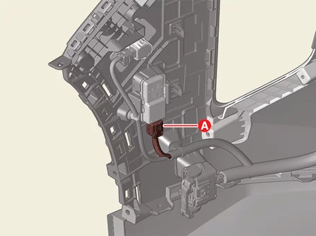
|
| 3.
|
Remove the unit (A).
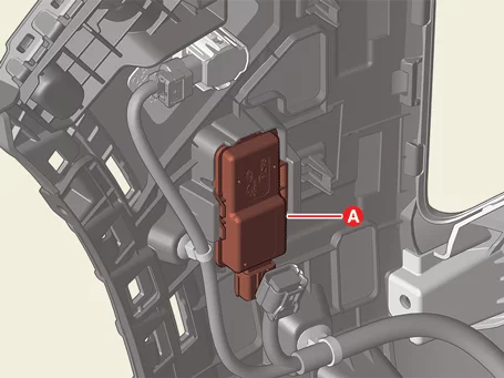
|
Ultra Wideband Unit [Rear Bumper]
| 1.
|
Remove the rear bumper assembly.
(Refer to Front & Rear Bumper - "Rear Bumper
Assembly")
|
| 2.
|
Disconnect the unit connector (A).
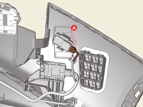
|
| 3.
|
Remove the unit (A).
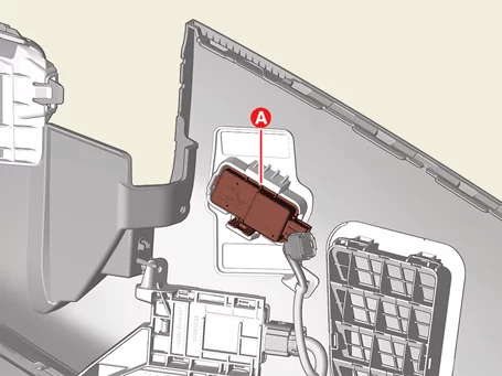
|
Ultra Wideband Unit [Rear Transverse Trim]
| 1.
|
Remove the rear transverse trim.
(Refer to Luggage Trim - "Rear Transverse Trim")
|
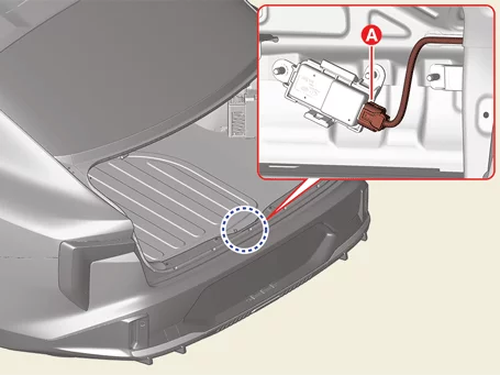
| 2.
|
Disconnect the unit connector (A).
|
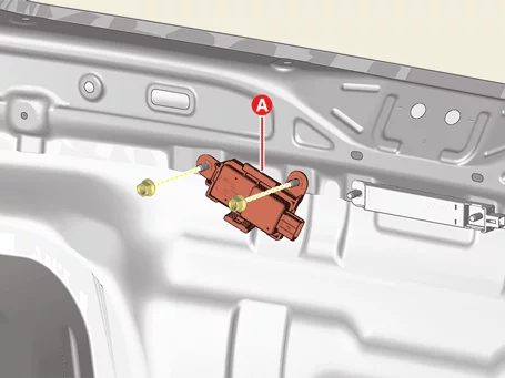
| 3.
|
Remove the unit (A) after removing the nuts.
|
Tightening torque:
3.9 - 4.2 N·m (0.40 - 0.43 kgf·m, 2.9 - 3.1 lb·ft, 34.7 - 37.3 lb·in)
|
|
Ultra Wideband and BLE Unit [4DR]
| 1.
|
Remove the roof trim assembly.
(Refer to Roof Trim - "Roof Trim Assembly")
|
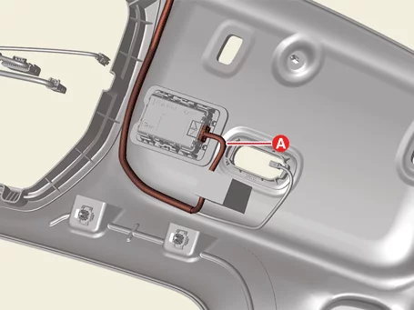
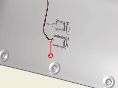
| 2.
|
Disconnect the unit connector (A).
Master
Slave
|
| 3.
|
Remove the unit (A).
Master
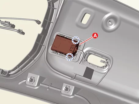
Slave
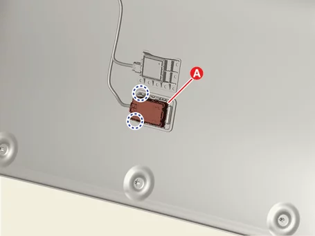
|
Ultra Wideband and BLE Unit [5DR]
| 1.
|
Remove the roof trim assembly.
(Refer to Roof Trim - "Roof Trim Assembly")
|
| 2.
|
Disconnect the unit connector (A).
Master
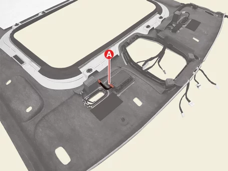
Slave
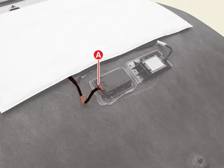
|
| 3.
|
Remove the unit (A).
Master
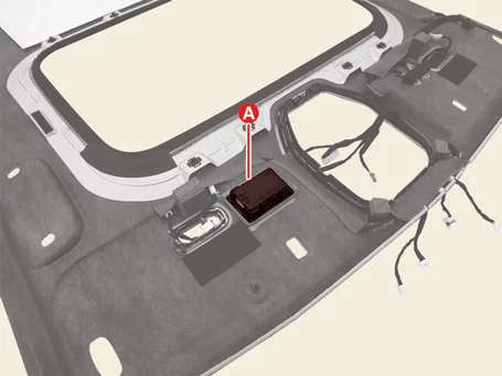
Slave
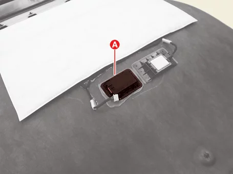
|
| 1.
|
Install in the reverse order of removal.
|
| 2.
|
When replacing the ultra-wideband and BLE unit, perform Over The Air (OTA) controller S/W
update with
KDS.
(Refer to Security & Vehicle Ignition System - "Over The
Air
(OTA)")
|
Junction Block On Vehicle Inspection
| 1.
|
PowerNet domain controllers can quickly diagnosed for problems with KDS. (Refer to "DTC Guide")
| (1)
|
Self diagnosis : Inspect the Diagnostic Trouble Code (DTC) with the KDS.
(Refer to DTC guide when fault code is found)
|
| (2)
|
S/W Management : Controlling other features including system option setting and
zero point
adjustment.
(S/W Management → Powernet Domain Controller → Variant Coding)
(S/W Management → Powernet Domain Controller → Mode Setting)
|
|
Refer to the KDS screen for operating conditions and details.
|
|
Junction Block Removal and Installation
|
The indication below represents the location of a clip or fastener.
|
PCB Block
| 1.
|
Disconnect the battery negative (-) terminal.
|
| 2.
|
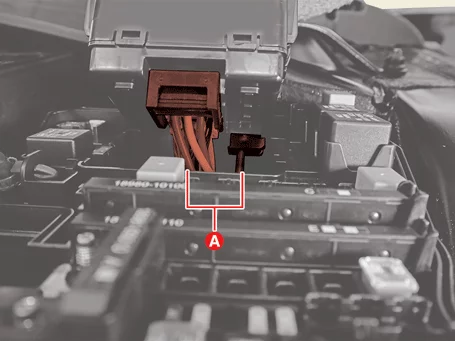
Disconnect the PCB block connector (A).
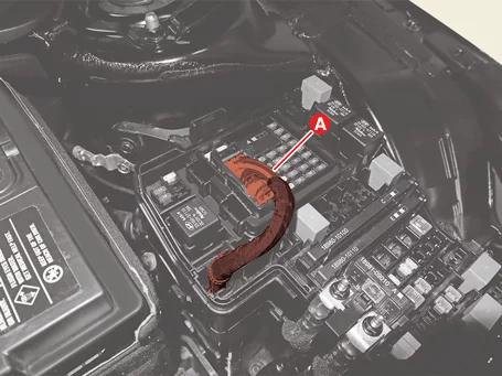
|
| 3.
|
Remove the PCB block (A).
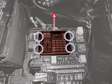
|
| 4.
|
Disconnect the PCB block connectors (A).
|
Powernet Domain Controller
| 1.
|
Remove the crash pad lower panel.
(Refer to Crash Pad - "Crash Pad Panel")
|
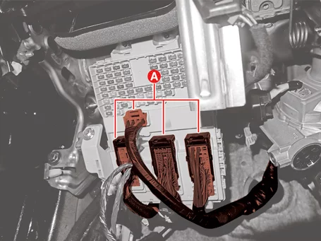
| 2.
|
Disconnect the unit connectors (A).
|
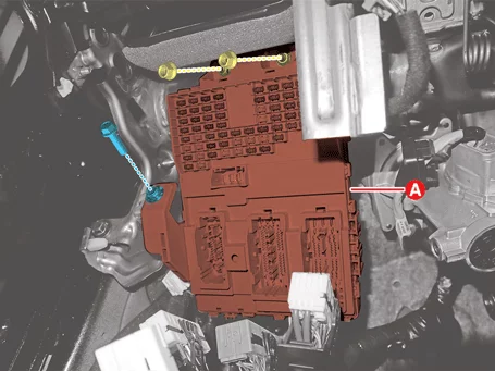
| 3.
|
Remove the unit (A) after removing the bolt and nuts.
|
Tightening torque
bolt : 6.9 - 9.8 N·m (0.7 - 1.0 kgf·m,
5.1 - 7.2 lb·ft)
nut : 5.9 - 8.8 N·m (0.6 - 0.9 kgf·m,
4.3 - 6.5 lb·ft,
52.1 - 78.1 lb·in)
|
|
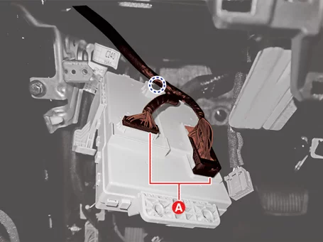
| 4.
|
Disconnect the unit connectors (A).
|
| 1.
|
Install in the reverse order of removal.
|
| 2.
|
Perform the order below with the KDS when replacing the powernet domain controller.
(S/W Management → Powernet Domain Controller → Variant Coding)
|
Refer to the KDS screen for operating conditions and details.
|
|
| 3.
|
Perform Over The Air (OTA) controller S/W update with KDS.
[Powernet
domain controller only]
(Refer to Security & Vehicle Ignition System - "Over The
Air
(OTA)")
|
Junction Block Inspection
Power Relay Inspection (Type A)
| 1.
|
Check for continuity between the terminals.
| (1)
|
After supplying power to between No. 85 and 86 power relay terminals, check
that there is
continuity between No. 30 and 87 terminals.
|
| (2)
|
After disconnecting power between No. 85 and 86 power relay terminals, check
that there is no
continuity between No. 30 and 87 terminals.
|
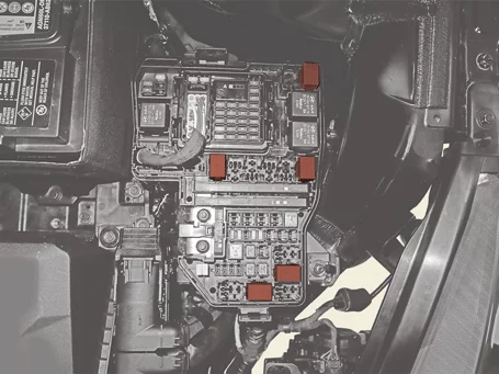
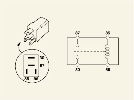
Terminal
|
Operate
|
IG ON
|
IG OFF
|
30 - 87
|
Continuity
|
-
|
|
Power Relay (Type B)
| 1.
|
Check for continuity between the terminals.
| (1)
|
After supplying power between terminal No. 85 and 86, check that there is
continuity between
terminal No. 30 and87.
|
| (2)
|
After disconnecting power between No. 85 and 86 power relay terminals, check
that there is no
continuity between No. 30 and 87 terminals.
|
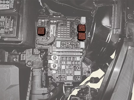
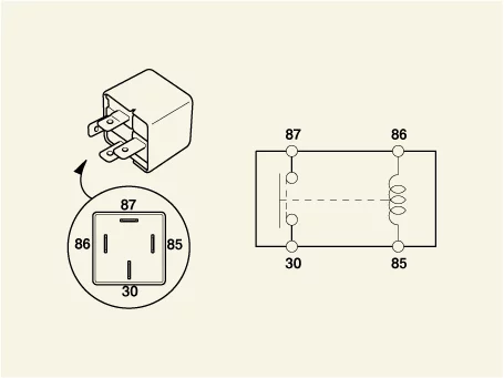
Terminal
|
Operate
|
IG ON
|
IG OFF
|
30 - 87
|
Continuity
|
-
|
|
Fuse
| 1.
|
Check for separation of fuse holder and check that the holder is tightly holding the fuse.
|
| 2.
|
Check that each fuse circuit has the exact fuse capacity.
|
| 3.
|
Check the fuses for any damage.
|
If a fuse is to be replaced, be sure to use a new fuse of the same capacity.
|
|
Multi-Fuse
| 1.
|
Disconnect the battery negative (-) terminal.
|
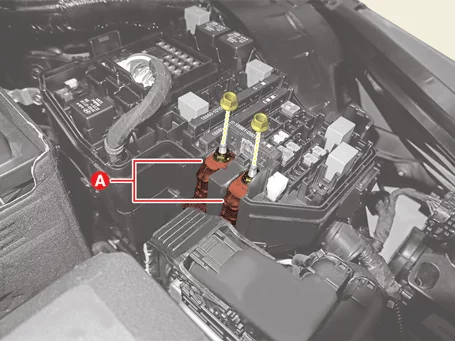
| 2.
|
Remove the terminals (A) after removing the nuts.
|
Tightening torque :
6.9 - 9.8 N·m (0.7 - 1.0 kgf·m, 5.1 - 7.2 lb·ft)
|
|
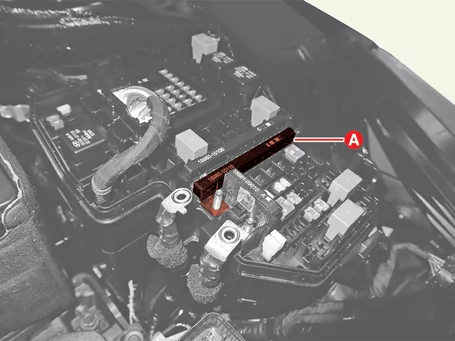
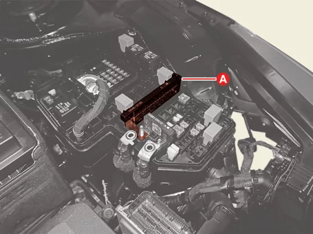
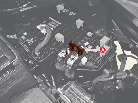
| 3.
|
Remove the multi-fuses (A).
|
| 4.
|
Check the multi-fuses for any damage.
|
Use the multi-fuse of the exact fuse capacity.
|
|
Over The Air (OTA) Description and Operation
| Description and Operation |
|
•
|
OTA (Over The Air) is a function that wirelessly updates the vehicle's controller software.
|
|
•
|
It provides a service that enables direct wireless communication to update the electronic
control unit
software, which was only possible by visiting a service center.
|
OTA System Flow Chart
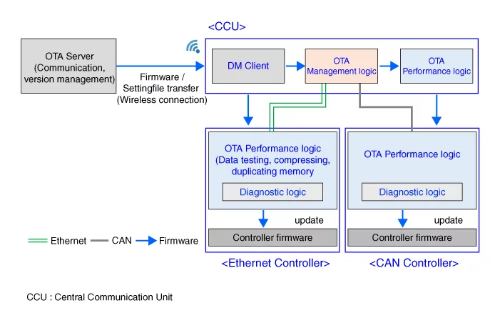
Over The Air (OTA) OTA Update Sequence
|
•
|
OTA update downloads S/W wirelessly while driving and updates after turning off
the vehicle.
|
|
•
|
Updates are performed in the following order.
|
|
| 1.
|
After stopping the vehicle, turn off the vehicle and update in order when the update approval
information
is displayed.
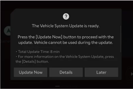
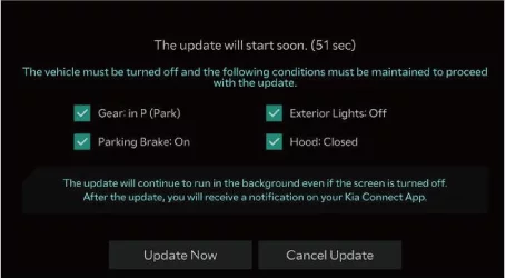
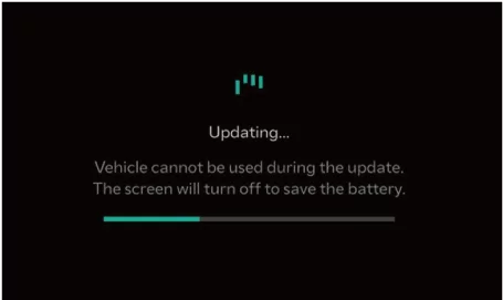
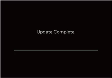
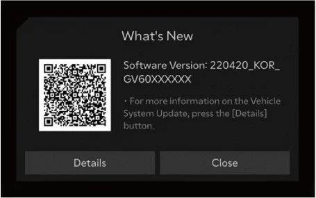
|
| 2.
|
After restarting the vehicle, the update information message is displayed.
|
When update fails, check "Part No" and "S/W version" with KDS and try again.
(Refer to Over The Air (OTA) - "On Vehicle
Inspection")
|
|
Over The Air (OTA) On Vehicle Inspection
|
•
|
This video was created using 3D graphics to help understand the vehicle
maintenance manual.
|
|
•
|
There may be some differences from actual vehicles.
|
|
•
|
The location and repair procedures of the parts may vary depending on vehicle
model, model year,
region, and specifications.
|
|
•
|
Check the KDS Guide for detailed information on how to use the KDS.
|
|
•
|
Check the manual for detailed maintenance procedures.
|
|
•
|
Unauthorized reproduction, distribution, or sharing of this video is
prohibited.
|
|
Over The Air (OTA) Management Version Update
(Click to play)

Video: Over The Air (OTA) Management Version
Update
OTA Target Controller
|
•
|
When replacing the OTA target controller, check the S/W version with KDS.
|
|
•
|
If the S/W version of the replaced controller is higher or lower than other
controller versions,
OTA automatic update is not possible.
|
|
No.
|
Controller
|
Detail
|
1
|
ECU
|
Engine Control Unit
|
2
|
TCU
|
Transmission Control Unit
|
3
|
ACU
|
Airbag Control Unit
|
4
|
ATCU
|
Auto Temperature Control Unit
|
5
|
MLM
|
Mood Lamp Module
|
6
|
MTC
|
Manual Temperature Control
|
7
|
ODS
|
Occupant Detection System
|
8
|
PTM
|
Power Trunk Module
|
9
|
RCM
|
Roof Control Module
|
10
|
SHVU
|
Seat Heater&Ventilation Unit
|
11
|
MDPS
|
Motor Driven Power Steering
|
12
|
ESC
|
Electronic Stability Control
|
13
|
ccNC
|
Connected Car Navigation Cockpit
|
14
|
CLU
|
Cluster
|
15
|
DCU
|
Data Connectivity Unit
|
16
|
EXT AMP
|
External Amplifier
|
17
|
HUD
|
Head Up display
|
18
|
ICC
|
In Cabin Camera
|
19
|
ADAS_DRV
|
ADAS Driving ECU
|
20
|
ADAS_PRK
|
ADAS Parking ECU
|
21
|
BMS
|
Battery Management System
|
22
|
CCU
|
Central Communication Unit
|
23
|
PDC
|
Powernet Domain Controller
|
24
|
P-LBM
|
Lithium Battery Module
|
25
|
BDC
|
Body Domain Controller
|
26
|
UWB_BLE
|
Ultra Wideband & Bluetooth Low Energy
|
27
|
WPC
|
UNIT ASSY-WIRELESS CHARGING
|
28
|
PSM
|
UNIT ASSY-MEMORY POWER SEAT
|
29
|
CDU
|
Climate Display Unit
|
30
|
MKBD
|
Multimedia Keyboard
|
Over The Air (OTA) Controller S/W Update
| 1.
|
Perform OTA management version update with the KDS.
|
| 2.
|
Turn off the vehicle and connect the KDS.
|
| 3.
|
Press the Start/Stop button to enter the “Vehicle Start” state.
|
| 4.
|
Select "Car Model" and select "ECU Upgrade".
|
| 5.
|
Select “OTA Management Version Update”.
|
•
|
It is possible to enter OTA management version update without
VCI 2 or ECI cable, but the
entry and update time may become longer.
|
|
•
|
Ethernet communication controller requires a dedicated cable
connection for OTA
management version update.
|
|
–
|
VCI 2: ECI module set for VCI 2
|
|
–
|
VCI 3: Ethernet Cable for VCI 3
|
|
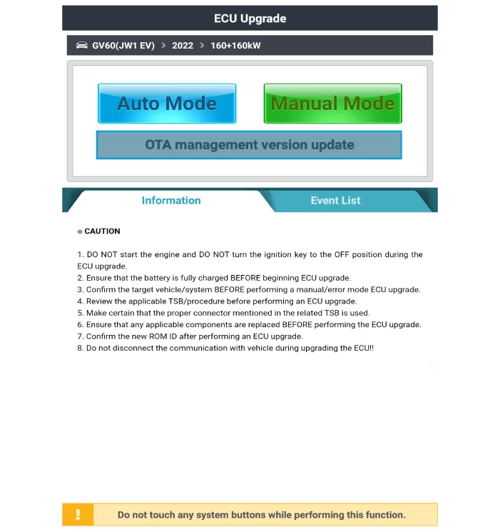
|
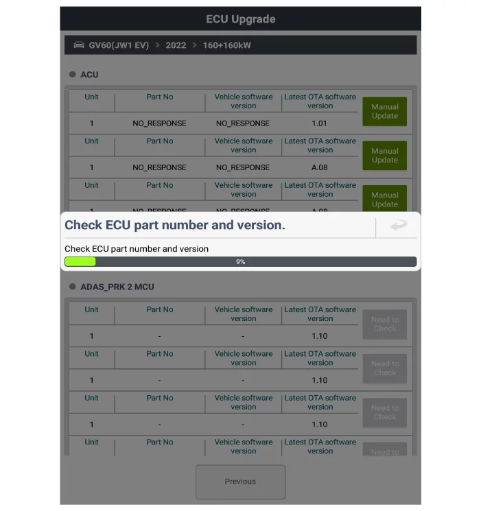
| 6.
|
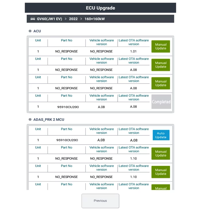
Update by checking the "Part No" and "S/W version" of the controller.
|
•
|
All active buttons must be updated. (Switch to inactive when
update is complete)
|
|
•
|
Manual Update Precautions
Before work, check if the controller is installed on the
vehicle, and if it is installed,
check the Part No. and perform the update. (Prevention of
erroneous specification update)
|
|
•
|
Conditions for activating the manual update button
|
| 1) |
Unable to read controller information (controller no response
or negative response)
|
| 2) |
Controller not mounted on vehicle
|
|
•
|
Conditions for activating the auto update button
|
| 1) |
Matching Part No. (same specifications)
|
| 2) |
Vehicle S/W version and OTA latest S/W version mismatch (update
required)
|
|
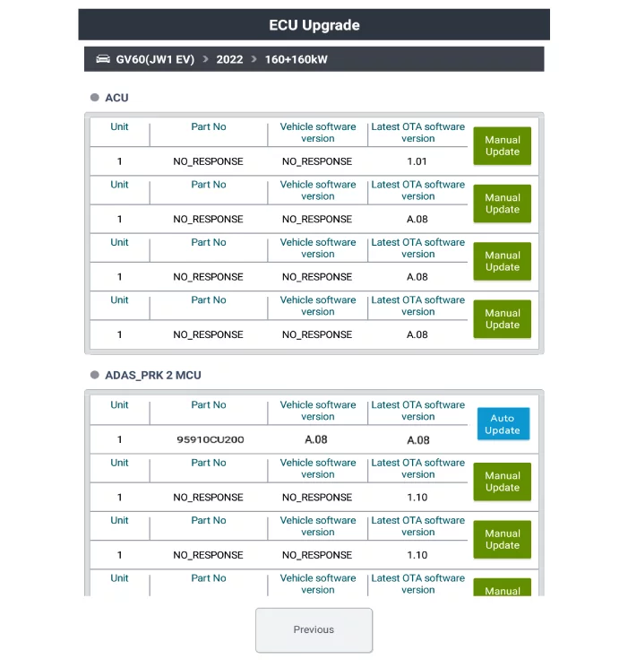
|
※ Automatic update procedure
Displays controller name, Part No, and S/W version information during auto
update
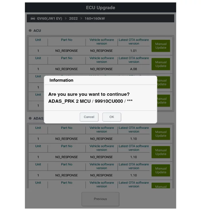
|
|
※ Manual update procedure
In a situation, it is difficult to check the controller specification through
KDS, check the Part
No. of the vehicle controller directly,
Perform an update after checking that it is the same as Part No. in the pop-up
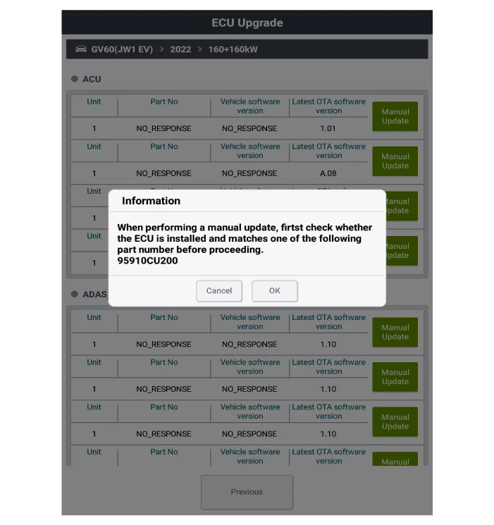
|
|
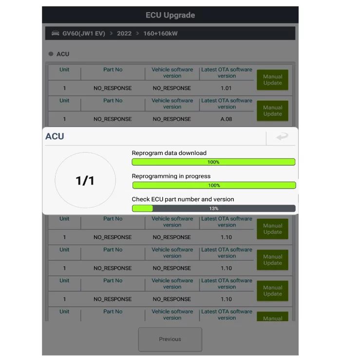
| 7.
|
Data download and reprogramming are in progress.
|
| 8.
|
When the update is completed, the activated update button is inactivated and the list is
updated with
completion.
|
| 9.
|
When the update fails, recheck the OTA management version update function entry conditions and
Part No.
|
When the update is complete, restart the vehicle, wait for 5 minutes, and check
if there is no
S/W ver error pop-up displayed in ccNC.
|
|
ROA (Rear Occupant Alert) System Description and Operation
The system detects the passenger in the vehicle and prevents the driver from getting off the vehicle with the
passenger in the back.
Sensor Detection
|
Sensing Control
|
Radar Sensing
|
Warning Control
|
Warning
|
Driver's door switch
Rear door switch
|
Body Domain Control Unit (BDC)
|
Rear Occupant Alert (ROA) Unit
|
Body Domain Control Unit (BDC)
|
Cluster pop-up and voice guidance
|
Horn + Hazard lamp
|
Kia Connect warning
|
|
–
|
1st warning : If you open the driver's door after you open and then close the rear door and IG
OFF, the
system provides warning by showing message on the cluster and giving voice instruction.
|
| 1) |
The system detects the indoor movement using the rear occupant alert sensor installed on the
roof trim
when the driver gets off the vehicle and locks all the doors.
|
| 2) |
If any movement inside the vehicle is detected, horn is activated for 25 seconds and the mobile
text
message is sent. (If Kia Connect equipped)
|
ROA (Rear Occupant Alert) System On Vehicle Inspection
| 1.
|
The Rear Occupant Alert (ROA) system can be quickly diagnosed for problems with the KDS. (Refer
to "DTC
guide")
| (1)
|
Self diagnosis : Inspect the Diagnostic Trouble Code (DTC) with the KDS.
(Refer to DTC guide when fault code is found)
|
|
Refer to the KDS screen for operating conditions and details.
|
|
ROA (Rear Occupant Alert) System Removal and Installation - 4DR
Rear Occupant Alert (ROA)
| 1.
|
Remove the roof trim assembly.
(Refer to Roof Trim - "Roof Trim Assembly")
|
| 2.
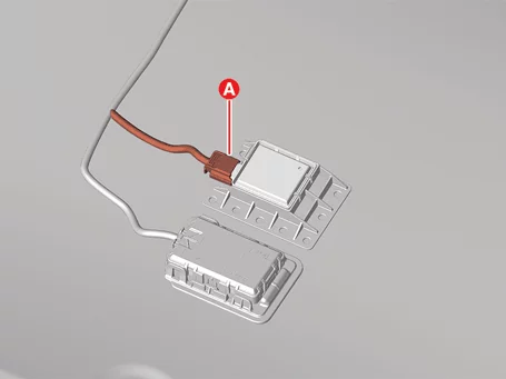
|
Disconnect the unit connector (A).
|
| 3.
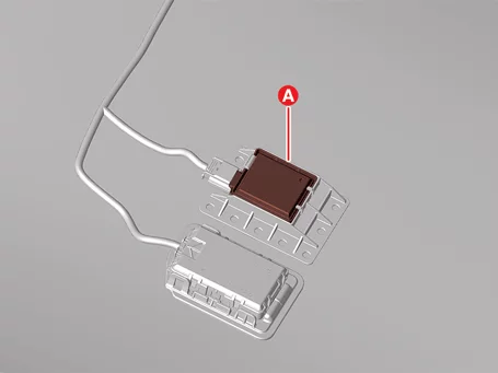
|
Remove the unit (A).
|
| 1.
|
Install in the reverse order of removal.
|
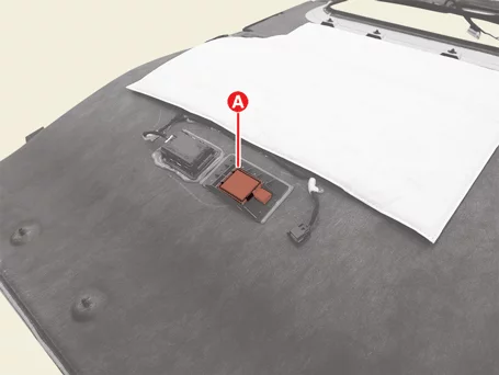
ROA (Rear Occupant Alert) System Removal and Installation - 5DR
Rear Occupant Alert (ROA)
| 1.
|
Remove the roof trim assembly.
(Refer to Roof Trim - "Roof Trim Assembly")
|
| 2.
|
Disconnect the unit connector (A).
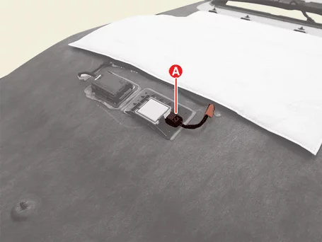
|
| 3.
|
Remove the unit (A).
|
| 1.
|
Install in the reverse order of removal.
|
Smart Key System
RF Receiver
Items
|
Specification
|
Frequency (MHz)
|
433.92
|
Antenna type
|
FSK
|
Smart Key
Items
|
Specification
|
Battery
|
Lithium battery 3 V 1EA (CR2450)
|
Distance
|
- The distance over which RF(Radio Frequency) Receiver can receive a FOB transmission signal : 30 m
(98.4
ft.)
- The distance over which LF(Low Frequency) antenna(Outer Handle/ Trunk Lid ) can detect FOB
: 0.7 m
(2.29 ft.)
|
Battery life
|
More than 2 years (10 times / a day)
|
Push buttons
|
3 (Door lock / unlock, Trunk unlock)
|
LF frequency (KHz)
|
125
|
RF frequency (MHz)
|
433.92
|
Numbers
|
2 units
|
|
An inappropriately disposed battery can be harmful to the environment and human health.
|
Antenna
Items
|
Specification
|
Operation temperature [°C (°F)]
|
-30 to 80°C (-22 to 176°F)
|
LF Frequency (KHz)
|
125
|
Numbers
|
Interior (3 units), Door (2 units), Exterior (1 units)
|
Smart Key System On Vehicle Inspection
| 1.
|
The smart key system can be more quickly diagnosed for problems with the KDS (Refer to "DTC
guide").
| (1)
|
Self diagnosis : Inspect the Diagnostic Trouble Code (DTC) with the KDS.
(Refer to DTC guide when fault code is found)
|
| (2)
|
S/W Management : Controlling other features including system option setting and
zero point
adjustment.
(S/W Management → IBU-SMK → Antenna Status Check)
(S/W Management → IBU-SMK → FOB KEY STATUS INFORMATION)
(S/W Management → IBU-SMK → ESCL STATUS INFORMATION)
(S/W Management → IBU-SMK → SMK STATUS INFORMATION)
(S/W Management → IBU-SMK → Neutralization Mode)
(S/W Management → IBU-SMK → Smart Key Code Saving)
|
|
|
Refer to the KDS screen for operating conditions and details.
|
Smart Key System Removal and Installation
|
The indication below represents the location of a clip or fastener.
|
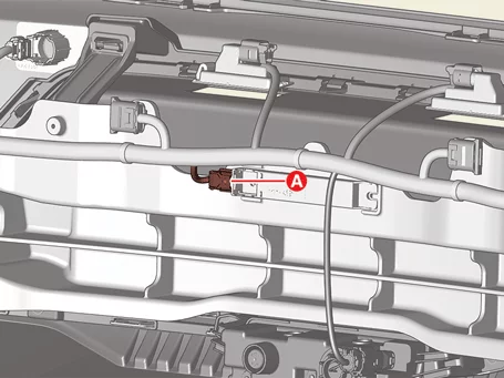
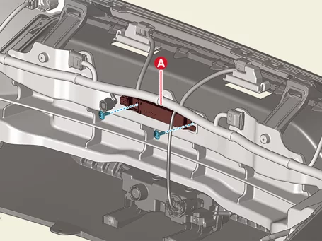
Rear Bumper Antenna [4DR]
| 1.
|
Remove the rear bumper assembly.
(Refer to Front & Rear Bumper - "Rear Bumper
Assembly”)
|
| 2.
|
Disconnect the antenna connector (A).
|
| 3.
|
Remove the antenna (A) after removing the screws.
|
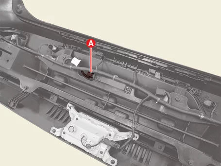
Rear Bumper Antenna [5DR]
| 1.
|
Remove the rear bumper assembly.
(Refer to Front & Rear Bumper - "Rear Bumper
Assembly”)
|
| 2.
|
Disconnect the antenna connector (A).
|
| 3.
|
Remove the antenna (A) after removing the screws.
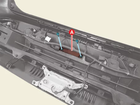
|
Interior Antenna #1
| 1.
|
Remove the Data Connectivity Unit (DCU).
(Refer to Security & Vehicle Ignition System - "Data
Connectivity
Unit (DCU)")
|
| 2.
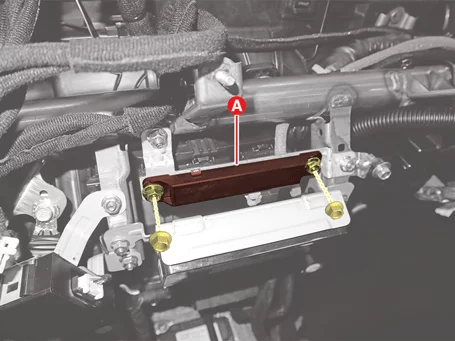
|
Remove the antenna (A) after removing the nuts.
|
Tightening torque:
3.9 - 4.2 N·m (0.40 - 0.43 kgf·m, 2.9 - 3.1 lb·ft, 34.7 - 37.3 lb·in)
|
|
| 3.
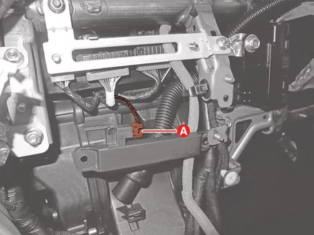
|
Disconnect the antenna connector (A).
|
Interior Antenna #2
| 1.
|
Remove the floor console assembly.
(Refer to Floor Console - "Floor Console Assembly")
|
| 2.
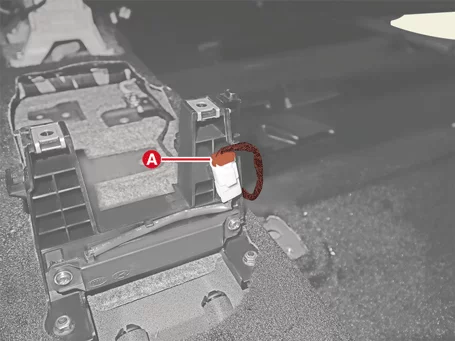
|
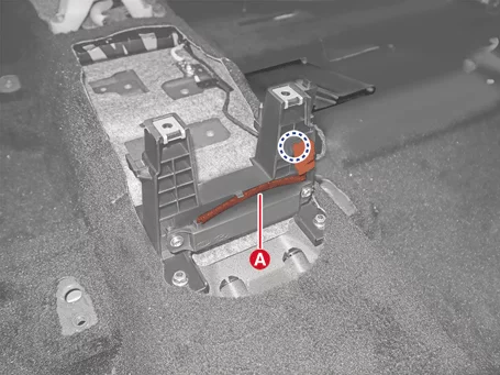
Disconnect the antenna connector (A).
|
| 3.
|
Separate the connector wiring (A).
|
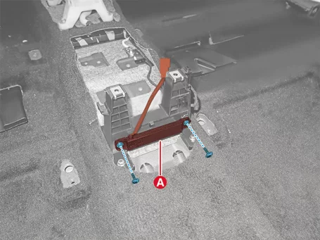
| 4.
|
Remove the antenna (A) after removing the screws.
|
Interior Antenna #3
| 1.
|
Disconnect the battery negative (-) terminal.
|
| 2.
|
Remove the rear transverse trim.
(Refer to Luggage Trim - "Rear Transverse Trim")
|
| 3.
|
Disconnect the antenna connector (A).
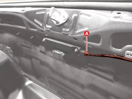
|
| 4.
|
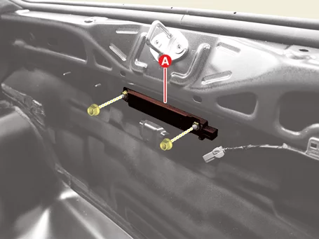
Remove the antenna (A) after removing the nuts.
|
Tightening torque:
3.9 - 4.2 N·m (0.40 - 0.43 kgf·m, 2.9 - 3.1 lb·ft, 34.7 - 37.3 lb·in)
|
|
Buzzer
| 1.
|
Remove the front bumper assembly.
(Refer to Front & Rear Bumper - "Front Bumper
Assembly")
|
| 2.
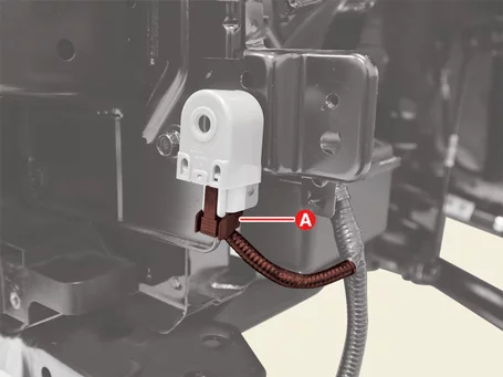
|
Disconnect the buzzer connector (A).
|
| 3.
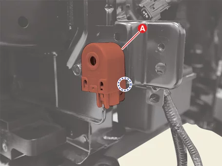
|
Remove the buzzer (A).
|
| 1.
|
Install in the reverse order of removal.
|
Other information:
Kia K4 (CL4) 2025-2026 Service Manual: Evasive Steering Assist function:
The Evasive Steering Assist function is a cutting-edge safety feature within the Forward Collision-Avoidance Assist (FCA) system of your Kia K4. Its primary purpose is to provide active steering support when emergency braking alone may be insufficient to avoid a collision. The core capability of this system is defined as "Emergency Steering."
Emergency Steering (Driver steering assist)
Emergency Steering
When the system detects a collision risk with another vehicle, pedestrian, cyclist, or motorcyclist in the path of your Kia K4, the Emergency Steering function alerts you.
Kia K4 (CL4) 2025-2026 Service Manual: Warning and indicator lights
The comprehensive array of warning and indicator lights integrated into your Kia K4 dashboard is designed to provide immediate, critical feedback regarding your vehicle's status. These illuminated icons inform the driver whether various onboard functions are currently activated, or they act as proactive alerts to situations that require driver attention and caution.