Contents:
Description and Operation
Automatic transaxle control system relies on various measurements to determine the current control status and
determine the necessary compensation values. These values are used to control the actuators and achieve the
desired
control output.
System Flow Chart
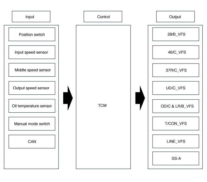
*28/B_VFS : 28 Brake Control Solenoid Valve
*46/C_VFS : 46 Clutch Control Solenoid Valve
*37R/C_VFS : 37R Clutch Control Solenoid Valve
*UD/C_VFS : UD Clutch Control Solenoid Valve
*OD/C & LR/B_VFS : OD Clutch & LR Brake Control Solenoid Valve
*T/CON_VFS : Torque Converter Control Solenoid Valve
*LINE_VFS : Line Pressure Control Solenoid Valve
*SS-A_ON/OFF : SS-A Solenoid Valve
Adjustment
|
•
|
This video was created using 3D graphics to help understand the vehicle
maintenance manual.
|
|
•
|
There may be some differences from actual vehicles.
|
|
•
|
The location and repair procedures of the parts may vary depending on vehicle
model, model year,
region, and specifications.
|
|
•
|
Check the KDS Guide for detailed information on how to use the KDS.
|
|
•
|
Check the manual for detailed maintenance procedures.
|
|
•
|
Unauthorized reproduction, distribution, or sharing of this video is
prohibited.
|
|
TCM learning
(Click to play)

Video: TCM learning
TCM learning
|
•
|
When shift shock occurs or parts related with the automatic transaxle are replaced, TCM
learning should
be performed.
|
|
•
|
In the following case, TCM learning is required.
|
|
–
|
Automatic transaxle assembly replacement
|
|
–
|
TCM upgrade or replacement
|
|
–
|
Valve body assembly replacement
|
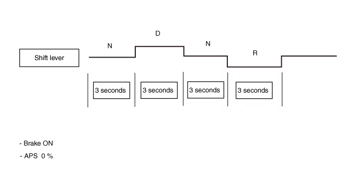
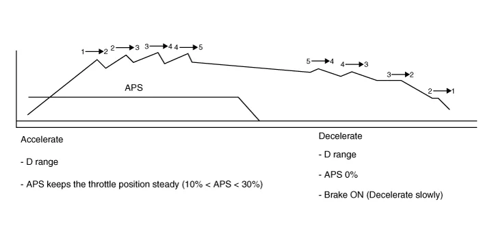
TCM adaptive values learning procedure : Repeat the above procedure at
least three times as shown in the pattern of illustration below.
|
•
|
Static relearn (condition : ATF temperature 35 - 95°C (95 - 203°F)
|
|
•
|
Driving relearning
|
Transaxle Control Module (TCM) Description and Operation
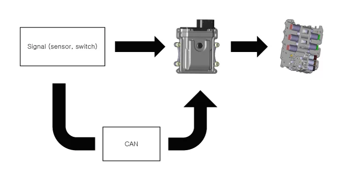
The module receives and processes signals from various sensors and implements a wide range of transaxle
controls
to ensure optimal driving conditions for the driver.
Function
|
•
|
Monitors the vehicle's operating conditions to determine the optimal gear setting.
|
|
•
|
Performs a gear change if the current gear setting differs from the identified optimal gear
setting.
|
|
•
|
Determines the need for torque converter clutch activation and engages the clutch accordingly.
|
|
•
|
Calculates the optimal line pressure level by constantly monitoring the torque level and
adjusts the
pressure accordingly.
|
|
•
|
Diagnoses the faults and failures for automatic transaxle.
|
Transaxle Control Module (TCM) Removal and Installation
| 1.
|
Perform in the order below using the KDS. (When replacing with a new TCM)
(S/W Management → Automatic Transaxle → Oil-pressure Characteristics BackUp & Input)
|
Refer to the KDS screen for operating conditions and details.
|
|
| 2.
|
Remove the engine room under cover.
(Refer to Engine Mechanical System - "Engine Room Under
Cover")
|
| 3.
|
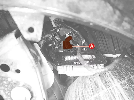
Disconnect the TCM connector (A).
|
| 4.
|
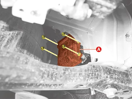
Remove the TCM (A) after removing the nuts.
|
Tightening torque :
9.8 - 11.8 N·m (1.0 - 1.2 kgf·m, 7.2 - 8.7 lb·ft)
|
|
| 1.
|
Install in reverse order of removal.
|
| 2.
|
Perform in the order below using the KDS. (When replacing with a new TCM)
(S/W Management → Automatic Transaxle → Oil-pressure Characteristics BackUp & Input)
|
Refer to the KDS screen for operating conditions and details.
|
|
| 3.
|
Perform TCM learning procedure.
(Refer to Automatic Transaxle Control System -
"Adjustment")
|
Oil Temperature Sensor (E Module) Specification
Oil Temperature [°C (°F)]
|
Sensor Resistance (kΩ)
|
-40 (-40)
|
48.1
|
-20 (-4)
|
15.6
|
0 (32)
|
5.88
|
20 (68)
|
2.51
|
40 (104)
|
1.12
|
60 (140)
|
0.612
|
80 (176)
|
0.329
|
100 (212)
|
0.186
|
120 (248)
|
0.109
|
140 (284)
|
0.067
|
150 (302)
|
0.053
|
Oil Temperature Sensor (E Module) Components and Components Location
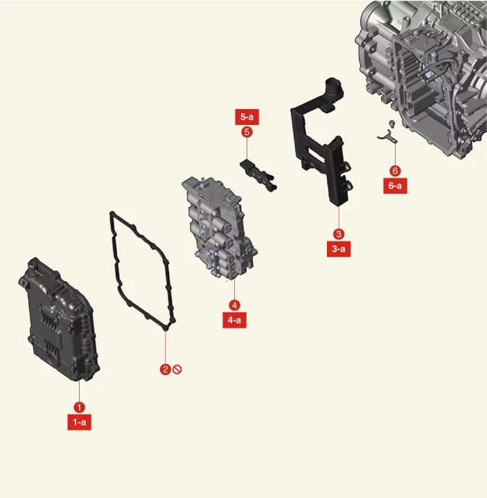
1. Valve Body
Cover
1-a.
11.8 - 13.7 N·m (1.2 - 1.4 kgf·m, 8.7 - 10.1 lb·ft)
2. Valve Body Cover Gasket
3. Oil
Temperature Sensor
(E Module)
3-a. 9.8 - 11.8 N·m (1.0 - 1.2 kgf·m, 7.2 - 8.7 lb·ft)
|
4. Valve Body
4-a. 9.8 - 11.8 N·m (1.0 -
1.2 kgf·m,
7.2 - 8.7 lb·ft)
5. Speed Sensor
5-a. 9.8 - 11.8 N·m (1.0 - 1.2 kgf·m, 7.2 - 8.7 lb·ft)
6.
Clip
6-a. 9.8 - 11.8 N·m (1.0 - 1.2 kgf·m, 7.2 - 8.7 lb·ft)
|
Oil Temperature Sensor (E Module) Description and Operation
|
•
|
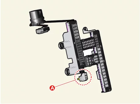
The sensor used is a thermistor (NTC) (A) in which resistance changes with temperature
variation.
|
|
•
|
When the TCM supplies about 5 V of power to the sensor, the sensor output value changes
depending on ATF
temperature.
|
|
•
|
Oil temperature sensor is installed on the valve body and is integrated with E module.
|
Function
|
•
|
Automatic transaxle oil temperature sensor monitors the temperature of ATF and conveys the
readings to
TCM.
|
|
•
|
Data produced by this sensor is used to identify torque converter clutch activation and
deactivation
zones within the low temperature and high temperature range and to compensate hydraulic pressure
levels
during gear changes.
|
Oil Temperature Sensor (E Module) On Vehicle Inspection
| 1.
|
The automatic transaxle system can be more quickly diagnosed for problems by using the vehicle
diagnostic
system (KDS). (Refer to "DTC guide")
| (1)
|
Self diagnosis : Inspect the Diagnostic Trouble Code (DTC) using the KDS
(Refer to DTC guide when fault code is found.)
|
| (2)
|
Data analysis : Check the system input/output values
(Data Analysis → Recorded Data)
Oil Temperature [°C (°F)]
|
Sensor Resistance (kΩ)
|
-40 (-40)
|
48.1
|
-20 (-4)
|
15.6
|
0 (32)
|
5.88
|
20 (68)
|
2.51
|
40 (104)
|
1.12
|
60 (140)
|
0.612
|
80 (176)
|
0.329
|
100 (212)
|
0.186
|
120 (248)
|
0.109
|
140 (284)
|
0.067
|
150 (302)
|
0.053
|
|
|
Oil Temperature Sensor (E Module) Removal
|
•
|
This video was created using 3D graphics to help understand the vehicle
maintenance manual.
|
|
•
|
There may be some differences from actual vehicles.
|
|
•
|
The location and repair procedures of the parts may vary depending on vehicle
model, model year,
region, and specifications.
|
|
•
|
Check the KDS Guide for detailed information on how to use the KDS.
|
|
•
|
Check the manual for detailed maintenance procedures.
|
|
•
|
Unauthorized reproduction, distribution, or sharing of this video is
prohibited.
|
|
Oil Temperature Sensor (E Module) Removal
(Click to play)
Video: Oil Temperature Sensor (E Module)
Removal
|
•
|
Maintain clean condition so that foreign substance does not get into the
automatic transaxle.
|
|
•
|
Use a coated apron, latex gloves, and stainless tray to prevent foreign
substances from entering
the internal part of the automatic transaxle.
|
|
•
|
Automatic transaxle is composed of delicate components. Be careful not to cause
any damage on the
component when assembling and disassembling.
|
|
| 1.
|
Shift the gear to N.
|
Use wheel chocks to prevent vehicle from being moved accidentally.
|
|
| 2.
|
Remove the valve body assembly.
(Refer to Hydraulic System - "Valve Body")
|
| 3.
|
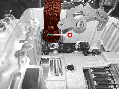
Disconnect the speed sensor connector (A).
|
| 4.
|
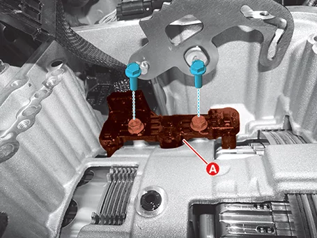
Remove the speed sensor (A) after removing the bolts.
|
Tightening torque :
9.8 - 11.8 N·m (1.0 - 1.2 kgf·m, 7.2 - 8.7 lb·ft)
|
|
| 5.
|
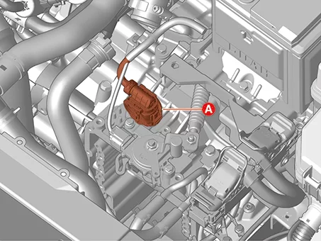
Disconnect the main connector (A).
|
| 6.
|
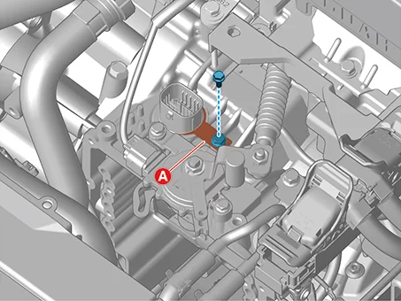
Remove the fixing clip (A) after removing the bolt.
|
Tightening torque :
9.8 - 11.8 N·m (1.0 - 1.2 kgf·m, 7.2 - 8.7 lb·ft)
|
|
| 7.
|
Remove the main connector (A) by pushing it downward.
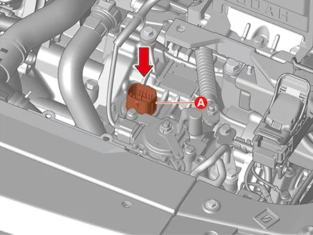
|
Oil Temperature Sensor (E Module) Installation
| 1.
|
Install in reverse order of removal.
|
•
|
When installing the valve body, make sure that the pin (B) of
the manual valve is
inserted into the detent lever (A).
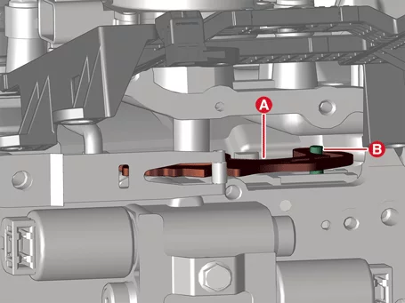
|
|
•
|
Lubricate main connector O-ring (A) and oil temperature sensor
O-ring (B) before
installing the E module.
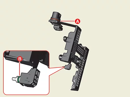
|
|
•
|
When installing, after mounting the E module, lightly tap the
connector part (A) to
insert the connector certainly and then tighten the bolts.
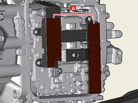
|
|
•
|
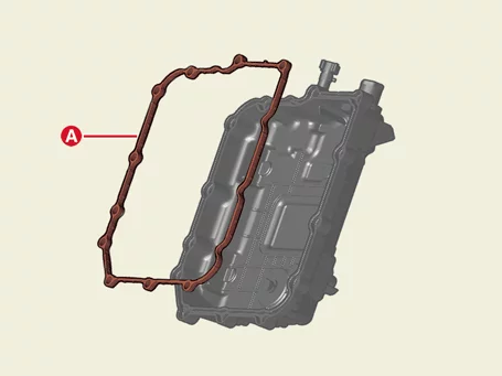
The existing valve body cover gasket (A) must be replaced with
a new one (do not reuse).
|
|
•
|
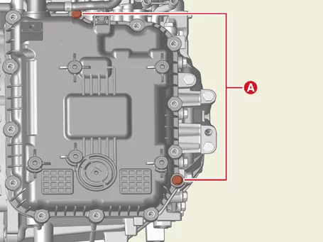
When installing the valve body cover, tighten the remaining
bolt after pre-tightening the
bolts (A).
|
|
•
|
When installing the clamp, be careful not to damage the hose.
|
|
|
| 2.
|
Check the ATF level after refilling the automatic transaxle with fluid.
(Refer to Hydraulic System - "Fluid")
|
| 3.
|
Check for leakage of coolant or fluid from hose connection while the engine is starting and
running.
|
Speed Sensor Specification
Item
|
Specification
|
Type
|
Hall effect sensor
|
Operating temperature [°C (°F)]
|
-40 to 150 (-40 to 302)
|
Power supply (V)
|
Maximum 9
|
Output signal (mA)
|
High : 11.8 - 16.8
|
Low : 5.9 - 8.4
|
Speed Sensor Components and Components Location
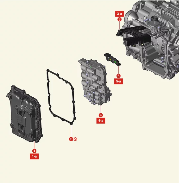
1. Valve Body
Cover
1-a.
11.8 - 13.7 N·m (1.2 - 1.4 kgf·m, 8.7 - 10.1 lb·ft)
2. Valve Body Cover Gasket
3. E
Module
3-a. 9.8 -
11.8 N·m (1.0 - 1.2 kgf·m, 7.2 - 8.7 lb·ft)
|
4. Valve Body
4-a. 9.8 - 11.8 N·m (1.0 -
1.2 kgf·m,
7.2 - 8.7 lb·ft)
5. Speed Sensor
5-a. 9.8 - 11.8 N·m (1.0 - 1.2 kgf·m, 7.2 - 8.7 lb·ft)
|
Speed Sensor Description and Operation
Input speed sensor : Used for detecting the speed of OD drum
Output speed sensor : Used for detecting the speed of transfer drive
gear
Middle speed sensor : It is used as a signal to reduce the engine torque
to detect the rotation speed of the front sun gear and prevent secondary damage to the transaxle in case of
abnormal
high-revving
Speed Sensor On Vehicle Inspection
| 1.
|
The automatic transaxle system can be more quickly diagnosed for problems by using the vehicle
diagnostic
system (KDS). (Refer to "DTC guide")
| (1)
|
Self diagnosis : Inspect the Diagnostic Trouble Code (DTC) using the KDS
(Refer to DTC guide when fault code is found.)
|
| (2)
|
Data analysis : Check the system input/output values
(Data Analysis → Recorded Data)
|
|
| 1.
|
Measure the signal waveform between the signal terminal on the main connector side and the
vehicle body
ground by using the KDS. (Refer to "DTC guide")
|
Speed Sensor Removal
|
•
|
Maintain clean condition so that foreign substance does not get into the
automatic transaxle.
|
|
•
|
Use a coated apron, latex gloves, and stainless tray to prevent foreign
substances from entering
the internal part of the automatic transaxle.
|
|
•
|
Automatic transaxle is composed of delicate components. Be careful not to cause
any damage on the
component when assembling and disassembling.
|
|
| 1.
|
Shift the gear to N.
|
Use wheel chocks to prevent vehicle from being moved accidentally.
|
|
| 2.
|
Remove the valve body assembly.
(Refer to Hydraulic System - "Valve Body")
|
| 3.
|
Disconnect the speed sensor connector (A).
|
| 4.
|
Remove the speed sensor (A) after removing the bolts.
|
Tightening torque :
9.8 - 11.8 N·m (1.0 - 1.2 kgf·m, 7.2 - 8.7 lb·ft)
|
|
Speed Sensor Installation
| 1.
|
Install in reverse order of removal.
|
•
|
When installing the valve body, make sure that the pin (B) of
the manual valve is
inserted into the detent lever (A).
|
|
•
|
Lubricate oil temperature sensor O-ring (A) before installing
the E module.
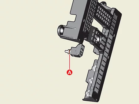
|
|
•
|
When installing, after mounting the E module, lightly tap the
connector part (A) to
insert the connector certainly and then tighten the bolts.
|
|
•
|
The existing valve body cover gasket (A) must be replaced with
a new one (do not reuse).
|
|
•
|
When installing the valve body cover, tighten the remaining
bolt after pre-tightening the
bolts (A).
|
|
|
| 2.
|
Check the ATF level after refilling the automatic transaxle with fluid.
(Refer to Hydraulic System - "Fluid")
|
| 3.
|
Check for leakage of coolant or fluid from hose connection while the engine is starting and
running.
|
Position Switch Specification
Item
|
Specification
|
Input power (V)
|
4.5 - 5.5
|
Output type
|
Shifting range (P/R/N/D)
|
Non-contact (2 channel PWM signal)
|
Start, Reverse
|
Contact
|
Position Switch Components and Components Location
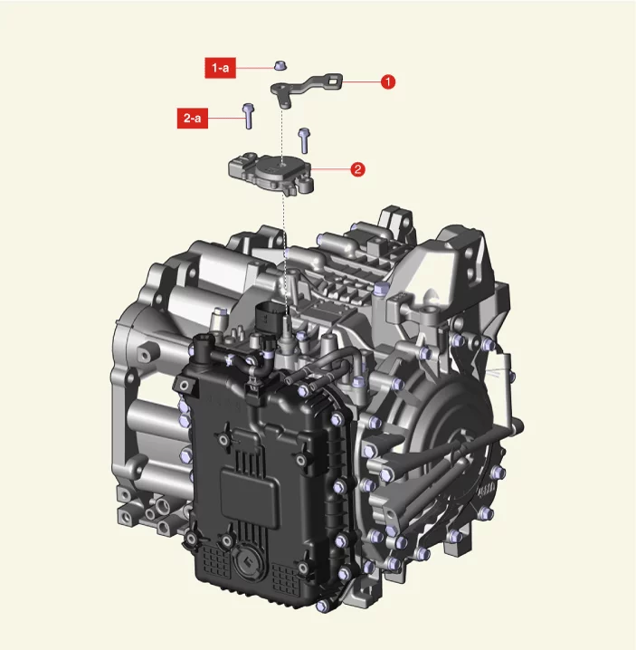
1. Manual Control
Lever
1-a. 17.7 - 24.5 N·m (1.8 - 2.5 kgf·m, 13 - 18.1 lb·ft)
|
2. Position Switch
2-a. 9.8 - 11.8 N·m (1.0
- 1.2
kgf·m, 7.2 - 8.7 lb·ft)
|
Position Switch Description and Operation
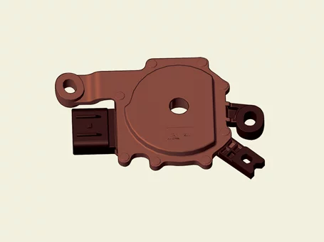
|
•
|
The position switch signals delivered at the TCM according to control of the shift lever
positions (P, R,
N, D) and it is used to control of the gear setting.
|
|
•
|
When the shift lever is placed in P or N range, it sends the output signal to the start relay.
|
|
•
|
When the shift lever is placed in R range, it sends the output signal to the back-up lamps.
|
Position Switch Troubleshooting
Position Switch On Vehicle Inspection
|
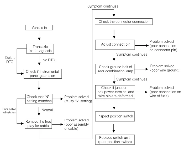
Inspect the following items by referring to inspection flow chart.
(Refer to Position Switch - "Troubleshooting")
|
| 1.
|
Check the diagnostic trouble codes (DTC) using KDS.
|
| 2.
|
Check that "N" range setting matches.
(Refer to Position Switch - "Installation")
|
| 3.
|
Check the free play for shift cable.
(Refer to Shift Cable - "Installation")
|
| 4.
|
Check the condition of connector.
| (1)
|
Inspect connector thoroughly for looseness, poor connection, bending,
corrosion, contamination,
deformation, or damage.
|
| (2)
|
Measure the voltage between the power supplied to the position switch circuit
and the ground.
|
|
| 5.
|
Inspect the ground of rear combination lamp circuit.
|
| 6.
|
Inspect the wiring connection of junction box power terminal and fuse.
| (1)
|
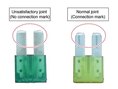
Check for separation of fuse holder and check that the holder is tightly
holding the fuse.
|
| (2)
|
Attach tester fuse to check that it is connected properly.
|
| (3)
|
Check if fuse is damaged.
|
|
| 7.
|
Check the position switch circuit signal.
| (1)
|
Turn ignition "ON", and engine "OFF".
|
| (2)
|
Measure the PWM output at each range (P, R, N, D).
|
|
Specification : Refer to table below
|
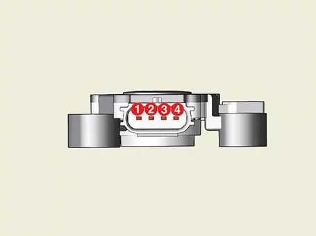
Signal (Pin)
|
PWM output value (%)
|
P
|
R
|
N
|
D
|
S1 (7)
|
10.0 - 30.7
|
37.6 - 56.9
|
59.1 - 74.3
|
76.5 - 90.0
|
S2 (8)
|
69.8 - 90.0
|
43.1 ~ 62.4
|
25.7 ~ 40.9
|
10.0 ~ 23.5
|
|
Position Switch Removal
| 1.
|
Shift the gear to N.
|
Use wheel chocks to prevent vehicle from being moved accidentally.
|
|
| 2.
|
Disconnect the battery negative ( - ) terminal.
|
| 3.
|
Remove the air cleaner assembly.
(Refer to Engine Mechanical System - "Air Cleaner")
|
| 4.
|
Disconnect the position switch connector (A).
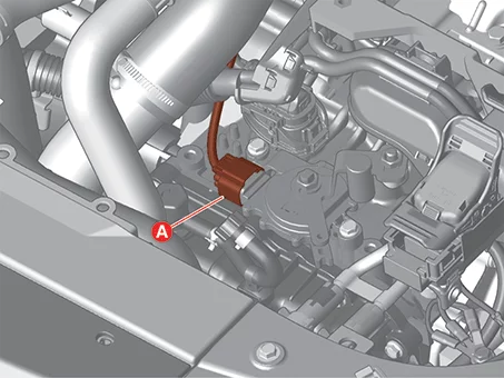
|
| 5.
|
Remove the shift cable by removing the nut (A).
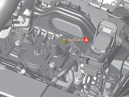
|
| 6.
|
Remove the manual control lever (A) and the washer after removing the nut.
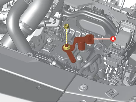
|
| 7.
|
Remove the position switch (A) after removing the bolts.
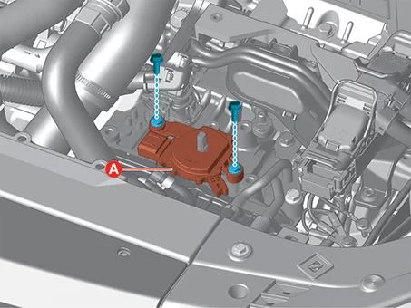
|
Position Switch Installation
Tool Name / Number
|
Illustration
|
Description
|
Position switch guide pin
09480 - A3800
|
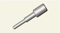
|
Used for fixing N range when installing position switch
|
| 1.
|
Check that the shift lever is placed in the N range.
|
| 2.
|
Install the position switch (A).
|
Lightly tighten the mounting bolts so that necessary adjustments can be made.
|
|
| 3.
|
Install the manual control lever (A).
|
Lightly tighten the mounting nut so that necessary adjustments can be made.
|
|
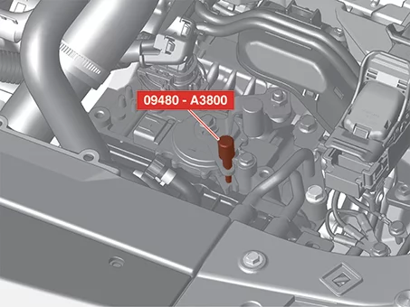
| 4.
|
Align the hole in the manual control lever with the "N" position hole of the position switch
and then
insert the SST (09480 - A3800).
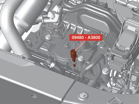
|
| 5.
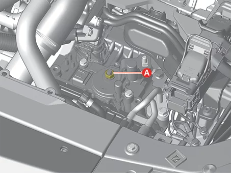
|
Tighten the manual control lever nut (A) to the specified torque.
|
Tightening torque :
17.7 - 24.5 N·m (1.8 - 2.5 kgf·m, 13.0 - 18.1 lb·ft)
|
|
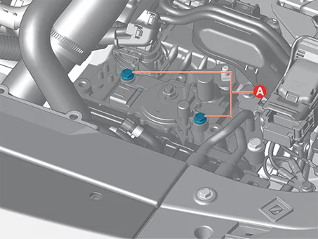
| 6.
|
Tighten the position switch bolts (A) to the specified torque.
|
Tightening torque :
9.8 - 11.8 N·m (1.0 - 1.2 kgf·m, 7.2 - 8.7 lb·ft)
|
|
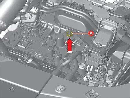
| 7.
|
Tighten the nut (A) to the specified torque after removing free play by pushing the shift cable
in the
direction of the arrow.
|
Tightening torque :
9.8 - 13.7 N·m (1.0 - 1.4 kgf·m, 7.2 - 10.1 lb·ft)
|
|
| 8.
|
Remove the SST (09480 - A3800).
|
| 9.
|
Connect the position switch connector (A).
|
| 10.
|
Install the air cleaner assembly.
(Refer to Engine Mechanical System - "Air Cleaner")
|
Shift Lever Components and Components Location
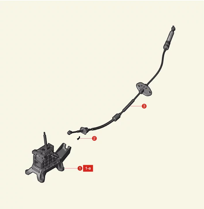
1. Shift Lever
1-a. 8.8 - 13.7 N·m (0.9 -
1.4
kgf·m, 6.5 - 10.1 lb·ft)
|
2. Snap Pin
3. Shift Cable
|
Shift Lever Removal and Installation
| 1.
|
Place the shift lever in the 'N' position.
|
Use wheel chocks to prevent vehicle from being moved accidentally.
|
|
| 2.
|
Disconnect the battery negative ( - ) terminal.
|
| 3.
|
Remove the floor console assembly.
(Refer to Body - “Floor Console Assembly”)
|
| 4.
|
Disconnect the connector (A).
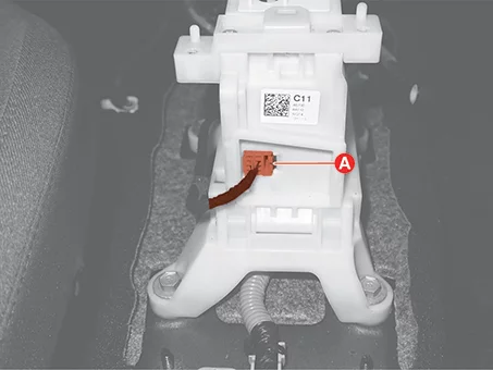
|
| 5.
|
Remove the wiring clips (A).
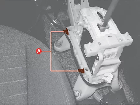
|
| 6.
|
Remove the snap pin (A).
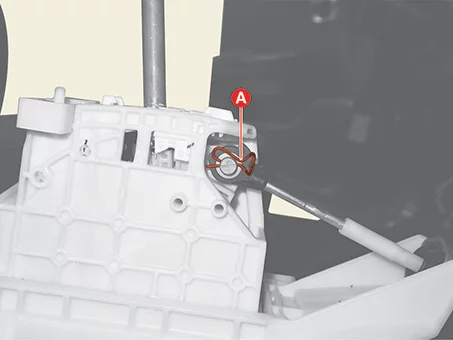
|
| 7.
|
Remove the shift cable (A) from the shift lever.
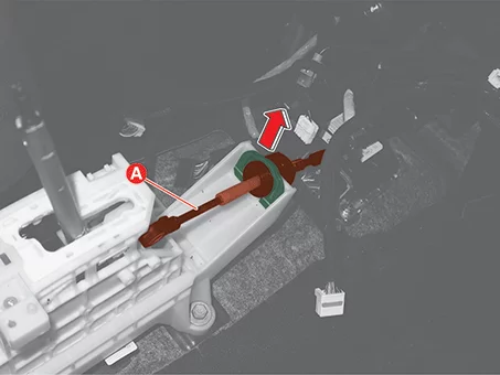
|
| 8.
|
Remove the shift lever assembly (A) after removing the bolts.
|
Tightening torque :
8.8 - 13.7 N·m (0.9 - 1.4 kgf·m, 6.5 - 10.1 lb·ft)
|
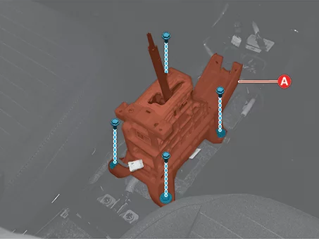
|
| 1.
|
Install in reverse order of removal.
|
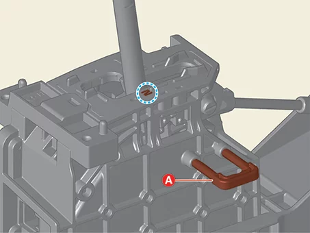
•
|
Insert "N" range fixing pin (A) of shift lever after checking
shift lever and the manual
control lever are in the "N" range before installation.
|
|
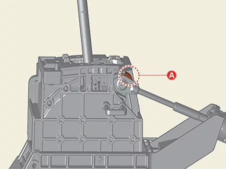
•
|
Install the shift cable after checking the direction of tab (A)
to prevent incorrect
assembly.
|
|
•
|
Mind the installation direction of snap pin and install the
snap pin with the hook facing
upward.
|
|
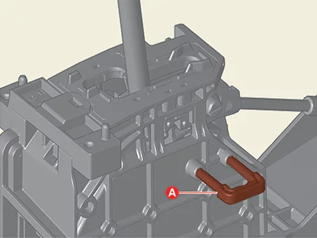
•
|
Make sure to get rid of "N" range fixing pin (A) after
installing the shift lever
assembly.
|
|
|
Shift Cable Components and Components Location
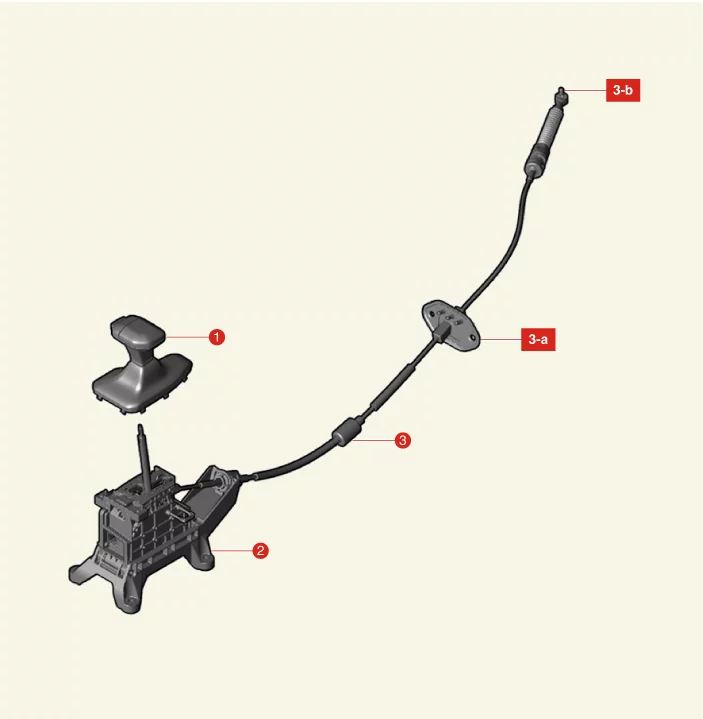
1. Gear Knob
2. Shift Lever
2. Shift
Cable
|
3-a. 11.8 - 14.7 N·m (1.2 - 1.5 kgf·m , 8.7 -
10.8
lb·ft)
3-b. 9.8 - 13.7 N·m (1.0 - 1.4 kgf·m, 7.2 - 10.1 lb·ft)
|
Shift Cable Removal
| 1.
|
Place the shift lever in the 'N' position.
|
Use wheel chocks to prevent vehicle from being moved accidentally.
|
|
| 2.
|
Remove the air cleaner assembly.
(Refer to Engine Mechanical System - "Air Cleaner")
|
| 3.
|
Remove the battery and battery tray.
(Refer to Engine Electrical System - "Battery")
|
| 4.
|
Remove the shift cable by removing the nut (A).
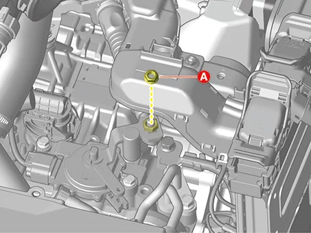
|
| 5.
|
Remove the shift cable (A) from the bracket (B).
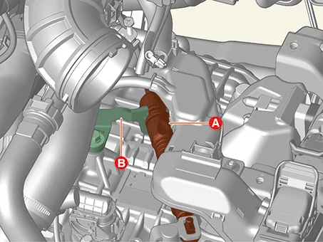
|
| 6.
|
Remove the floor console assembly.
(Refer to Body - "Floor Console Assembly")
|
| 7.
|
Remove the snap pin (A).
|
| 8.
|
Remove the shift cable (A) from the shift lever.
|
| 9.
|
Remove the accelerator position sensor.
(Refer to Engine Control / Fuel System - "Accelerator Position
Sensor
(APS)")
|
| 10.
|
Remove the shift cable retainer (A) after removing the nuts. Then, remove the shift cable by
pulling it
toward the vehicle interior.
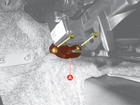
|
Shift Cable Installation
Tool Name / Number
|
Illustration
|
Description
|
Position switch guide pin
09480 - A3800
|
|
Used for fixing N range when installing position switch
|
| 1.
|
Checking shift lever and the manual control lever are in the N range before installation.
|
| 2.
|
Install the shift cable retainer (A).
|
Tightening torque :
11.8 - 14.7 N·m (1.2 - 1.5 kgf·m , 8.7 - 10.8 lb·ft)
|
|
| 3.
|
Install the accelerator position sensor.
(Refer to Engine Control / Fuel System - "Accelerator Position
Sensor
(APS)")
|
| 4.
|
Install the shift cable (A) to the shift lever.
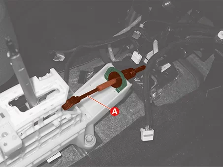
|
Install the shift cable after checking the direction of tab (A) to prevent
incorrect assembly.
|
|
| 5.
|
Insert the snap pin (A).
|
Mind the installation direction of snap pin and install the snap pin with the
hook facing upward.
|
|
| 6.
|
Install the shift cable (A) to the bracket (B).
|
Replace the shift cable bracket clip with a new one.
|
|
| 7.
|
Align the hole in the manual control lever with the N position hole of the position switch and
then
insert the SST (09480 - A3800).
|
| 8.
|
Tighten the nut (A) to the specified torque after removing free play by pushing the shift cable
in the
direction of the arrow.
|
Tightening torque :
9.8 - 13.7 N·m (1.0 - 1.4 kgf·m, 7.2 - 10.1 lb·ft)
|
|
| 9.
|
Remove the SST (09480 - A3800).
|
| 10.
|
Install the floor console assembly.
(Refer to Body - "Floor Console Assembly")
|
| 11.
|
Install the battery and battery tray.
(Refer to Engine Electrical System - "Battery")
|
| 12.
|
Install the air cleaner assembly.
(Refer to Engine Mechanical System - "Air Cleaner")
|
| 13.
|
Check that operating surely at each range of the inhibitor switch corresponding to each
position of shift
lever.
|
Other information:
Kia K4 (CL4) 2025-2026 Service Manual: Wireless smartphone charging system
The Kia K4 features an advanced wireless smartphone charging system conveniently located at the front of the center console, allowing you to power your mobile devices without the clutter of cables.
Charging indicator light
Wireless charging pad surface
To ensure proper operation, firmly close all vehicle doors and start the Kia K4 engine or set the ignition to the ON position.
Kia K4 (CL4) 2025-2026 Service Manual: Winter driving
Severe winter weather conditions significantly increase the risk of road hazards, accelerate tire wear, and demand proactive maintenance. To ensure your Kia K4 remains reliable and safe throughout the colder months, please follow these professional recommendations for winter operation.
Snowy or icy conditions
Navigating through deep snow or on packed ice often requires specialized equipment, such as dedicated winter tires or appropriate tire chains, to maintain adequate grip.