Contents:
Components and Components Location
| Components and Components Location |
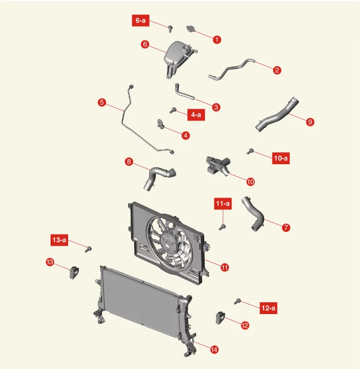
1. Reservoir Tank
Cap
2.
Reservoir Tank Hose
2. Water Hose
4. Clip
4-a. 3.9 - 5.9 N·m (0.4 - 0.6 kgf·m, 2.9 - 4.3
lb·ft, 34.7
- 52.1 lb·in)
5. Degassing Hose
6. Reservoir Tank
6-a. 7.8 - 11.8 N·m (0.8 - 1.2 kgf·m,
5.8 - 8.7
lb·ft)
7. Radiator Upper Hose
8. Radiator Lower Hose
|
9. Filler Neck
Hose
10.
Filler Neck
10-a. 7.8 - 11.8 N·m (0.8 - 1.2 kgf·m, 5.8 - 8.7 lb·ft)
11. Cooling Fan
11-a.
4.9 - 7.8
N·m (0.5 - 0.8 kgf·m, 3.6 - 5.8 lb·ft, 43.4 - 69.4 lb·in)
12. LH Radiator Mounting Bracket
12-a. 7.8 -
11.8 N·m (0.8 - 1.2 kgf·m, 5.8 - 8.7 lb·ft)
13. RH Radiator Mounting Bracket
13-a.7.8 - 11.8
N·m (0.8 -
1.2 kgf·m, 5.8 - 8.7 lb·ft)
14. Radiator
|
Description and Operation
|
•
|
This video was created using 3D graphics to help understand the vehicle
maintenance manual.
|
|
•
|
There may be some differences from actual vehicles.
|
|
•
|
The location and repair procedures of the parts may vary depending on vehicle
model, model year,
region, and specifications.
|
|
•
|
Check the KDS Guide for detailed information on how to use the KDS.
|
|
•
|
Check the manual for detailed maintenance procedures.
|
|
•
|
Unauthorized reproduction, distribution, or sharing of this video is
prohibited.
|
|
Coolant Flow
(Click to play)

Video: Coolant Flow
Troubleshooting
| Engine Overheat Troubleshooting |
Visual Inspection
How to inspect
|
Correction
|
Inspect for shortage of coolant in reservoir tank.
|
Reinspect after refilling coolant.
|
Check coolant contamination after removing the pressure cap
|
Be careful of burns when removing the pressure cap in vehicles with overheated
engine
|
|
Reinspect after replacing coolant.
|
Inspect for leakage and loose coolant hoses (radiator hose, heater hose, oil cooler hose, etc.).
|
Reinspect for leakage after reinstalling hoses and clamps.
|
Inspect for coolant leaks in each part of the Integrated Thermal Management Module (ITM)
|
Replace ITM gasket or replace unit if necessary.
|
Inspect for leakage on water inlet fitting mounting part.
|
Reinspect for leakage after replacing O-ring.
|
Inspect drive belt (for normal operation of water pump).
|
Adjust or replace drive belt tension
|
Inspect for leakage on water pump gasket mounting part.
|
Reinspect for leakage after replacing gasket.
|
Reinspect for leakage after tightening to the specified torque.
|
Inspect for loose coolant temperature sensor, cooling fan connector and pin.
|
Reinstall loose connector.
|
Replace relevant part if connector pin is damaged.
|
Inspect operation status of cooling fan.
|
–
|
Check operation status by switching ON/OFF the heater control A/C.
|
|
Will not operate in cold ambient temperature.
|
|
Check mounting status of ground cable.
|
Diagnostic Device
How to inspect
|
Correction
|
Inspect self-diagnostic code using KDS.
|
Check coolant temperature sensor, wiring, connector, etc.
|
Component Inspection
How to inspect
|
Correction
|
Inspect water pump impeller.
|
Replace the water pump.
|
Coolant Replacement
|
•
|
This video was created using 3D graphics to help understand the vehicle
maintenance manual.
|
|
•
|
There may be some differences from actual vehicles.
|
|
•
|
The location and repair procedures of the parts may vary depending on vehicle
model, model year,
region, and specifications.
|
|
•
|
Check the KDS Guide for detailed information on how to use the KDS.
|
|
•
|
Check the manual for detailed maintenance procedures.
|
|
•
|
Unauthorized reproduction, distribution, or sharing of this video is
prohibited.
|
|
Engine Coolant Air Bleeding with KDS
(Click to play)
Video: Engine Coolant Air Bleeding with KDS
Engine Coolant Air Bleeding without KDS
(Click to play)
Video: Engine Coolant Air Bleeding without
KDS
| Engine Coolant Refilling and Air Bleeding |
|
•
|
Do not remove the pressure cap when the engine is hot.
|
|
•
|
Serious scalding could be caused by hot coolant under high pressure escaping
from the reservoir
tank.
|
|
|
•
|
Be sure to add coolant according to the ITM coolant refill method.
|
|
•
|
When replenishing coolant, be careful not to spill on the belt, electrical
devices.
|
|
By using the KDS, replace coolant and bleed air out.
| 1.
|
Make sure the engine and radiator are cool to the touch.
|
| 2.
|
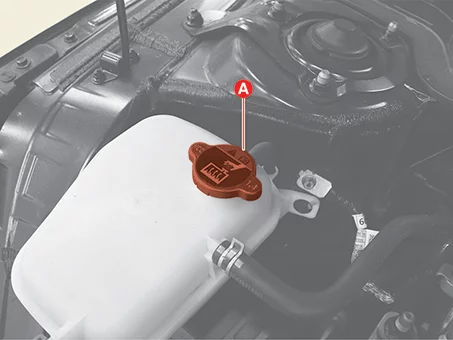
Remove the pressure cap (A).
|
| 3.
|
Remove the engine room under cover.
(Refer to Engine and Transaxle Assembly - "Engine Room Under
Cover")
|
| 4.
|
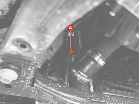
Remove the drain plug (A) and drain the coolant.
|
| 5.
|
After draining the coolant, re-tighten the drain plug.
|
| 6.
|
Drain coolant and inside the reservoir tank, and then clean it.
|
| 7.
|
Fill mixture of the antifreeze and water (45 - 60%) as much as possible through the reservoir
tank inlet
while IG-OFF.
|
Coolant capacity : Approximately 7.2 ℓ
(1.90 U.S gal,
7.61 U.S.qt., 6.34 Imp.qt.)
|
|
•
|
Press the radiator upper/lower hoses to allow air to escape
easily.
|
|
•
|
For best cooling performance, use a antifreeze that meets
vehicle specifications.
Genuine antifreeze is an antifreeze whose quality and
performance are guaranteed by Kia.
|
|
•
|
Do not mix antifreeze/coolant from different brands.
|
|
•
|
Do not add any anti-rust.
|
|
•
|
Use only distilled water when mixing antifreeze with water.
|
|
•
|
If the concentration of coolant is less than 45%, corrosion or
freezing may occur, and if
the concentration of coolant is more than 60%, the cooling
effect may be reduced, so the
concentration of coolant shall be maintained at 50 to 55%.
|
|
|
| 8.
|
Connect KDS in IG-ON state.
|
| 9.
|
Perform the Integrated Thermal Management Module (ITM) coolant filling mode" using KDS.
|
Refer to the KDS screen for operating conditions and details
|
|
| 11.
|
Fill the reservoir tank with coolant.
|
When the coolant temperature reaches 90°C (194° F) or 20 minutes have passed
since the engine
start, check the coolant level in the reservoir tank and replenish.
|
|
| 12.
|
Stop the Integrated Thermal Management Module (ITM) cooling water filling mode" using KDS.
|
| 13.
|
Run the engine until enough coolant circulates.
|
| 14.
|
Check the Coolant capacity in the reservoir tank, refill it to the "MAX" (or "FULL") line.
|
| 15.
|
Install the engine room under cover.
(Refer to Engine and Transaxle Assembly - "Engine Room Under
Cover")
|
When using KDS is not possible, replace the coolant and bleed the air
out.
| 1.
|
Make sure the engine and radiator are cool to the touch.
|
| 2.
|
Remove the pressure cap (A).
|
| 3.
|
Remove the engine room under cover.
(Refer to Engine and Transaxle Assembly - "Engine Room Under
Cover")
|
| 4.
|
Remove the drain plug (A) and drain the coolant.
|
| 5.
|
After draining the coolant, re-tighten the drain plug.
|
| 6.
|
Drain coolant and inside the reservoir tank, and then clean it.
|
| 7.
|
Remove the air cleaner assembly.
(Refer to Intake and Exhaust System - "Air Cleaner")
|
| 8.
|
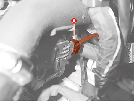
Disconnect the Integrated Thermal Management Module (ITM) connector (A).
|
•
|
When disconnecting the Integrated Thermal Management Module
(ITM) connector (A), make
sure the engine and all power are OFF.
|
|
•
|
Be careful not to apply static electricity or other voltage to
the Integrated Thermal
Management Module (ITM).
|
|
•
|
Do not bring magnetic objects such as magnets close to the
Integrated Thermal Management
Module (ITM).
|
|
|
| 9.
|
Fill mixture of the antifreeze and water (45 - 60%) as much as possible through the reservoir
tank inlet.
|
Coolant capacity : Approximately 7.2 ℓ
(1.90 U.S gal,
7.61 U.S.qt., 6.34 Imp.qt.)
|
|
•
|
Press the radiator upper/lower hoses to allow air to escape
easily.
|
|
•
|
For best cooling performance, use a antifreeze that meets
vehicle specifications.
Genuine antifreeze is an antifreeze whose quality and
performance are guaranteed by Kia.
|
|
•
|
The coolant concentration should be kept at least 45-60% to
prevent corrosion. If the
coolant concentration is less than 45-60%, there is a risk of
corrosion and freezing.
|
|
•
|
It is not recommended if the concentration of the coolant
exceeds 60%, as the cooling
effect may be reduced.
|
|
•
|
Do not mix different brands of antifreeze and coolant.
|
|
•
|
Do not add any anti-rust.
|
|
•
|
When mixing coolant and water, use distilled water instead of
tap water.
|
|
|
| 11.
|
Fill the reservoir tank with coolant.
|
20 minutes have passed since the engine start, check the coolant level in the
reservoir tank and
replenish.
|
|
| 12.
|
Connect the Integrated Thermal Management Module (ITM) connector after turning OFF the engine.
|
| 13.
|
Repeat the engine ON/OFF and check the engine warning lamp OFF.
| (1)
|
Wait for 5 seconds with engine ON and then turn OFF the engine.
|
| (2)
|
Repeat the step (1) 3 times.
|
| (3)
|
Check the engine warning lamp OFF when engine is turned ON for the fourth time.
|
|
| 14.
|
Run the engine until enough coolant circulates.
|
| 15.
|
Check the Coolant capacity in the reservoir tank, refill it to the "MAX" (or "FULL") line.
|
| 16.
|
Remove the air cleaner assembly.
(Refer to Intake and Exhaust System - "Air Cleaner")
|
| 17.
|
Install the engine room under cover.
(Refer to Engine and Transaxle Assembly - "Engine Room Under
Cover")
|
Cooling Fan Components and Components Location
| Components and Components Location |
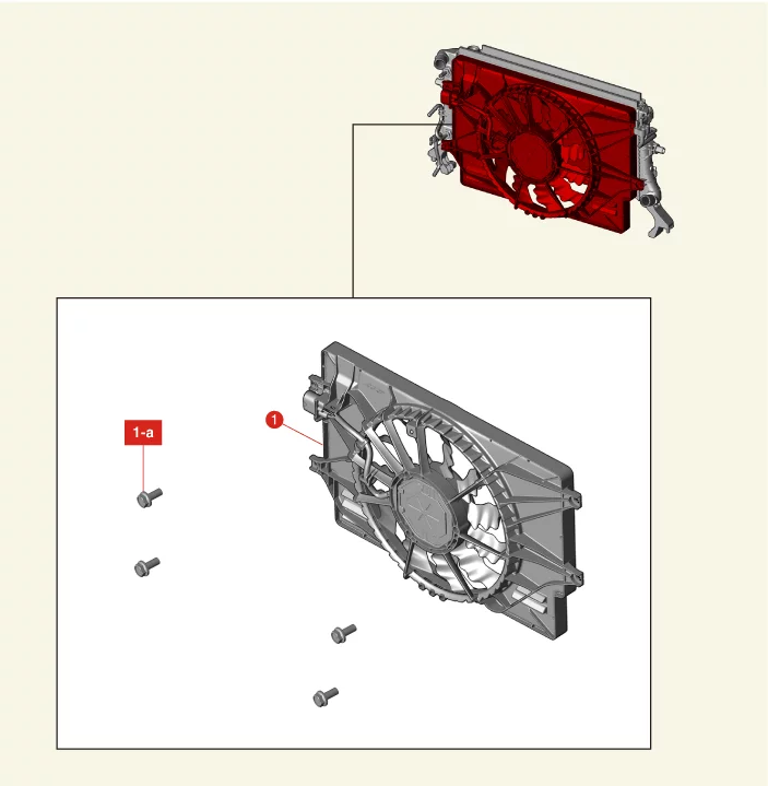
1. Cooling Fan
|
1-a. 4.9 - 7.8 N·m
(0.5 - 0.8
kgf·m, 3.6 - 5.8 lb·ft, 43.4 - 69.4 lb·in)
|
Cooling Fan Description and Operation
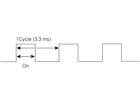
The cooling fan motor voltage is adjusted according to the duty cycle (frequency 300 Hz) applied by the ECU.
Cooling Fan Specification
Item
|
Specification
|
Fan type
|
PULLER
|
Fan speed control
|
PWM
|
Air flow rate (㎥/h)
|
2880 - 3000 min.
|
Fan speed (rpm)
|
2352 - 2548
|
Current (A)
|
46.2
|
Cooling Fan Removal and Installation
| 1.
|
Disconnect the battery negative ( - ) terminal.
|
| 2.
|
Remove the air cleaner assembly.
(Refer to Intake and Exhaust System - "Air Cleaner")
|
| 3.
|
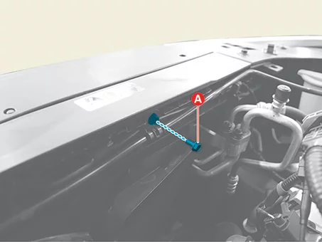
Remove the degassing hose clip bolt (A).
|
Tightening torque :
3.9 - 5.9 N·m (0.4 - 0.6 kgf·m, 2.9 - 4.3 lb·ft, 34.7 - 52.1 lb·in)
|
|
| 4.
|
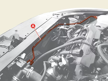
Disconnect the degassing hose (A).
|
| 5.
|
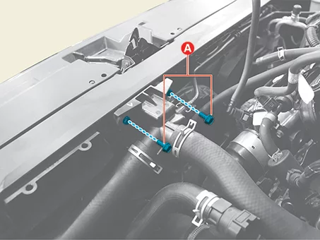
Remove the filler neck bolts (A).
|
Tightening torque :
7.8 - 11.8 N·m (0.8 - 1.2 kgf·m, 5.8 - 8.7 lb·ft)
|
|
| 6.
|
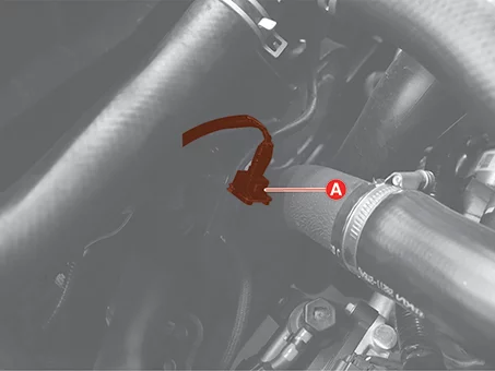
Disconnect the Recirculation Control Valve (RCV) connector (A).
|
| 7.
|
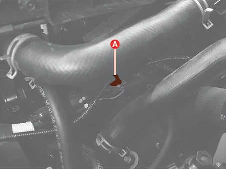
Separate the wiring clip (A).
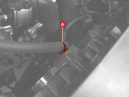
|
| 8.
|
Disconnect the cooling fan connector (A).
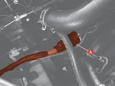
|
| 9.
|
Remove the cooling fan (A) after removing the bolts.
|
Tightening torque :
7.8 - 11.8 N·m (0.8 - 1.2 kgf·m, 5.8 - 8.7 lb·ft)
|
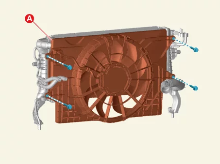
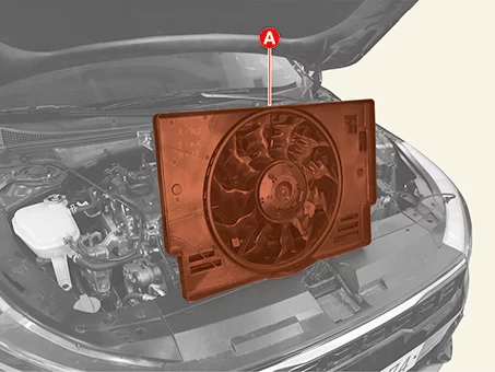
|
| 1.
|
Install in reverse order of removal.
|
Install to the specified torque.
|
|
Cooling Fan Inspection
Fan Motor
| 1.
|
After connecting the KDS, force the cooling fan motor.
|
There are 2 modes of forced fan motor drive.
|
[Fan motor low speed]
| (1)
|
Perform the "Fan motor low speed" on the KDS menu.
(Forced operation → Engine → Fan motor low speed)
|
[Fan motor high speed]
| (1)
|
Perform the "Fan motor high speed" on the KDS menu.
(Forced operation → Engine → Fan motor high speed)
|
|
Radiator Components and Components Location
| Components and Components Location |
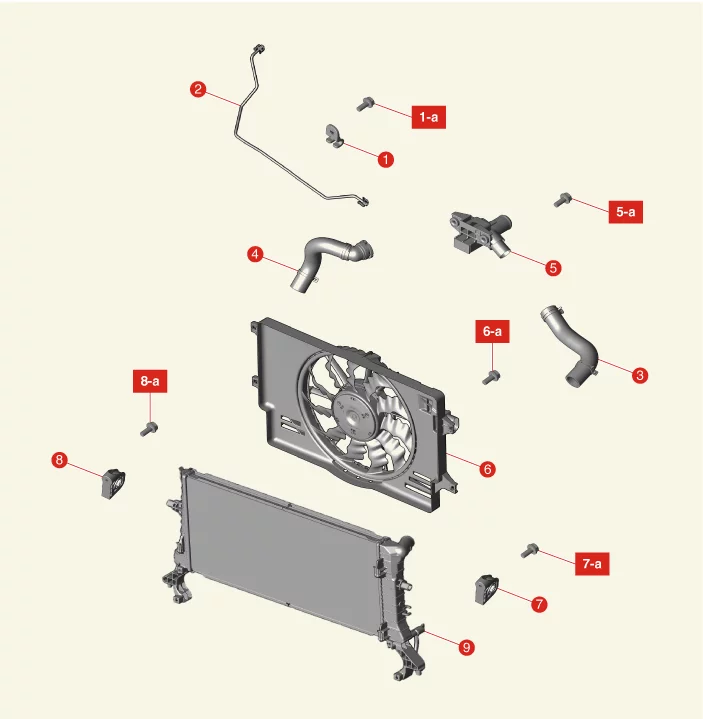
1. Clip
1-a. 3.9 -
5.9 N·m
(0.4 - 0.6 kgf·m, 2.9 - 4.3 lb·ft, 34.7 - 52.1 lb·in)
2. Degassing Hose
3. Radiator Upper
Hose
4.Radiator Lower Hose
5. Filler Neck
5-a. 7.8 - 11.8 N·m (0.8 - 1.2 kgf·m, 5.8 - 8.7
lb·ft)
|
6. Cooling Fan
6-a.
4.9 -
7.8 N·m (0.5 - 0.8 kgf·m, 3.6 - 5.8 lb·ft, 43.4 - 69.4 lb·in)
7. LH Radiator Mounting Bracket
7-a. 7.8
- 11.8 N·m (0.8 - 1.2 kgf·m, 5.8 - 8.7 lb·ft)
8. RH Radiator Mounting Bracket
8-a. 7.8 - 11.8
N·m (0.8 -
1.2 kgf·m, 5.8 - 8.7 lb·ft)
9. Radiator
|
Radiator Removal and Installation
| 1.
|
Disconnect the battery negative ( - ) terminal.
|
| 2.
|
Drain the coolant.
(Refer to Cooling System - "Coolant")
|
| 3.
|
Remove the air cleaner assembly.
(Refer to Intake and Exhaust System - "Air Cleaner")
|
| 4.
|
Remove the hood latch assembly.
(Refer to Body - "Hood latch assembly")
|
| 5.
|
Remove the cooling fan
(Refer to Cooling System - "Cooling Fan")
|
| 6.
|
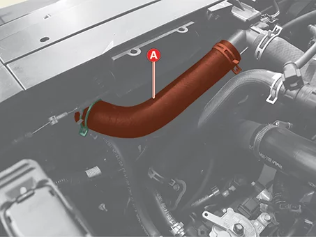
Disconnect the radiator upper hose (A) after releasing the clamp.
|
| 7.
|
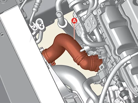
Disconnect the radiator lower hose (A) after releasing the clamp.
|
| 8.
|
Remove the front bumper assembly.
(Refer to Body - "Front Bumper Assembly")
|
| 9.
|
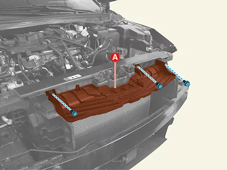
Remove the air duct (A) after removing the bolts.
|
Tightening torque :
3.9 - 5.9 N·m (0.4 - 0.6 kgf·m, 2.9 - 4.3 lb·ft, 34.7 - 52.1 lb·in)
|
|
| 10.
|
Remove the side air guard (A) after removing the bolts.
|
Tightening bolt :
3.9 - 5.9 N·m (0.4 - 0.6 kgf·m, 2.9 - 4.3 lb·ft, 34.7 - 52.1 lb·in)
|
[LH]
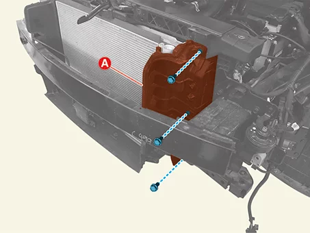
[RH]
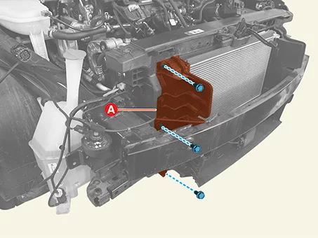
|
| 11.
|
Remove the intercooler air guide (A) after removing the bolts.
|
Tightening torque :
9.8 - 11.8 N·m (1.0 - 1.2 kgf·m, 7.2 - 8.7 lb·ft)
|
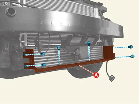
|
| 12.
|
Remove the intercooler bolts (A).
|
Tightening torque :
9.8 - 11.8 N·m (1.0 - 1.2 kgf·m, 7.2 - 8.7 lb·ft)
|
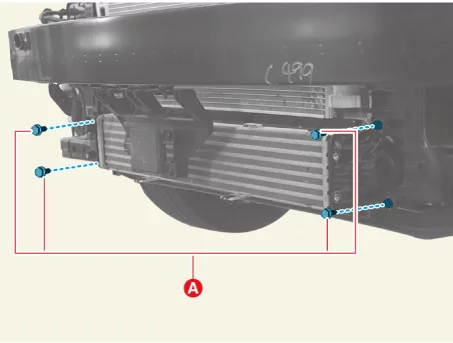
|
| 13.
|
Remove the front bumper beam.
(Refer to Body - "Front Bumper Beam Assembly")
|
| 14.
|
Separate the condenser (A).
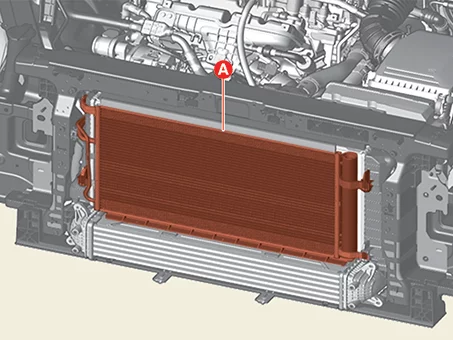
|
| 15.
|
Remove the radiator mounting bracket (A) after removing the bolts.
|
Tightening torque :
7.8 - 11.8 N·m (0.8 - 1.2 kgf·m, 5.8 - 8.7 lb·ft)
|
[RH]
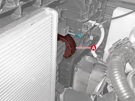
[LH]
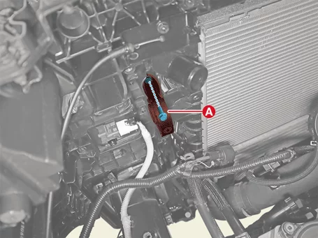
|
| 16.
|
Remove the radiator (A).
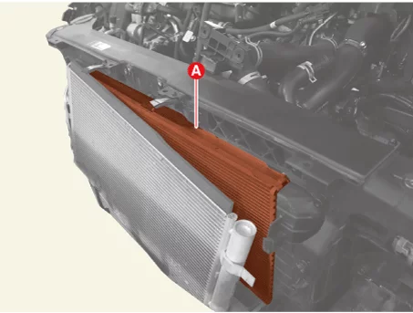
|
| 1.
|
Install in reverse order of removal.
|
•
|
Install the radiator to the specified torque.
|
|
•
|
When installing the quick connector hose, make sure it is
properly installed.
|
|
|
| 2.
|
Fill with coolant.
(Refer to Cooling System - "Coolant")
|
Be sure to add coolant according to the ITM coolant refill method.
|
|
Radiator Inspection
Pressure Cap
| 1.
|
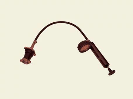
Remove the pressure cap, wet its seal with engine coolant, then install it on a pressure
tester.
|
| 2.
|
Apply a pressure of 122.6 - 152.0 kPa (1.25 - 1.55 kgf/cm², 17.8 - 22.0 psi).
|
| 3.
|
Check for a drop in pressure.
|
| 4.
|
If the pressure drops, replace the cap.
|
Radiator Leakage
| 1.
|
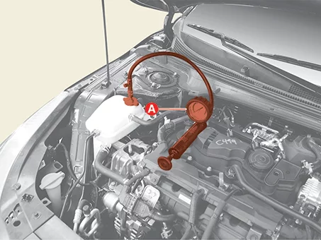
Wait until engine is cool, then carefully remove the pressure cap and fill the radiator with
engine
coolant, then install it on the pressure tester.
|
| 2.
|
Apply a pressure tester to the radiator and apply a pressure of 157.0 kPa (1.6 kg/cm², 22.77
psi).
|
| 3.
|
Inspect for engine coolant leaks and a drop in pressure
|
| 4.
|
Remove the tester and reinstall the pressure cap.
|
Check for engine oil in the coolant and/or coolant in the engine oil.
|
|
Reservoir Tank Components and Components Location
| Components and Components Location |
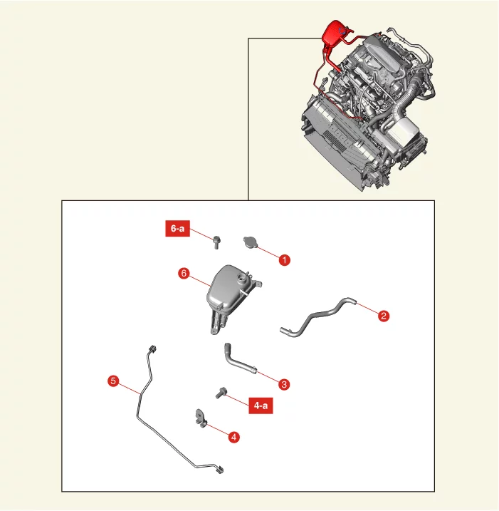
1. Reservoir Tank
Cap
2.
Reservoir Tank Hose
2. Water Hose
4. Clip
4-a. 3.9 - 5.9 N·m (0.4 - 0.6 kgf·m, 2.9 - 4.3
lb·ft, 34.7
- 52.1 lb·in)
|
5. Degassing
Hose
6.
Reservoir Tank
6-a. 7.8 - 11.8 N·m (0.8 - 1.2 kgf·m, 5.8 - 8.7 lb·ft)
|
Reservoir Tank Removal and Installation
| 1.
|
Drain the coolant.
(Refer to Cooling System - "Coolant")
|
| 2.
|
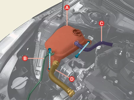
Remove the reservoir tank (A).
| (1)
|
Disconnect the degassing hose (B) after releasing the clamp.
|
| (2)
|
Disconnect the reservoir tank hose (C) after releasing the clamp.
|
| (3)
|
Disconnect the reservoir tank hose(D) after releasing the clamp.
|
| (4)
|
Remove the reservoir tank (A) after releasing the bolt.
|
Tightening torque :
7.8 - 11.8 N·m (0.8 - 1.2 kgf·m, 5.8 - 8.7 lb·ft)
|
|
|
| 1.
|
Install in reverse order of removal.
|
Install the reservoir tank to the specified torque.
|
|
| 2.
|
Fill with coolant.
(Refer to Cooling System - "Coolant")
|
Be sure to add coolant according to the ITM coolant refill method.
|
|
Integrated Thermal Management Module (ITM) Components and Components Location
| Components and Components Location |
| Integrated Thermal Management Module (ITM) |
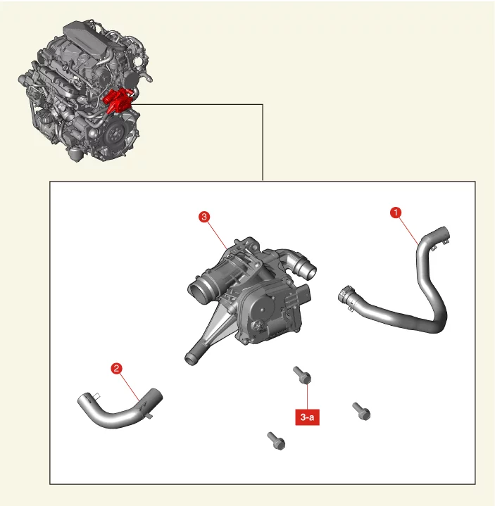
1. Heater Hose
2.
Oil
Cooler Hose
|
3. Integrated Thermal
Management Module (ITM)
3-a. 9.8 - 11.8 N·m (1.0 - 1.2 kgf·m, 7.2 - 8.7 lb·ft)
|
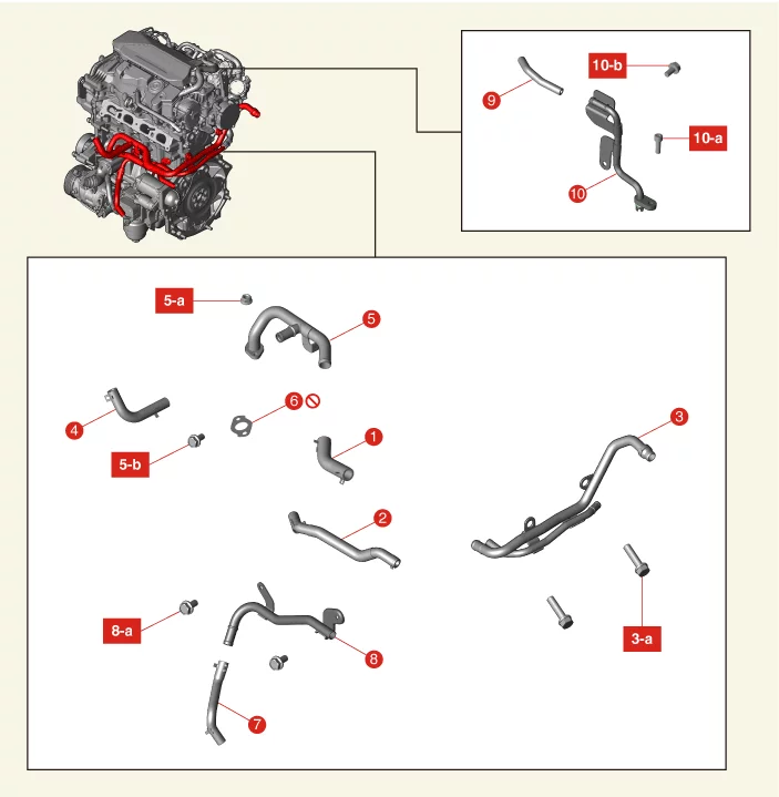
1. Heater Hose
2.
Heater
Pipe Hose
3. Heater Pipe
3-a. 14.7 - 21.6 N·m (1.5 - 2.2 kgf·m, 10.8 - 15.9 lb·ft)
4.
Return
Hose
5. Heater Pipe A
5-a. 9.8 - 11.8 N·m (1.0 - 1.2 kgf·m, 7.2 - 8.7 lb·ft)
5-b. 9.8 -
11.8 N·m
(1.0 - 1.2 kgf·m, 7.2 - 8.7 lb·ft)
6. Heater Pipe Gasket
|
7. Oil Cooler
Hose
8. Oil
Cooler Pipe
8-a. 9.8 - 11.8 N·m (1.0 - 1.2 kgf·m, 7.2 - 8.7 lb·ft)
9. Water Vent Hose
10.
Water Vent
Pipe
10-a. 9.8 - 11.8 N·m (1.0 - 1.2 kgf·m, 7.2 - 8.7 lb·ft)
10-b. 9.8 - 11.8 N·m (1.0 - 1.2
kgf·m, 7.2
- 8.7 lb·ft)
|
Integrated Thermal Management Module (ITM) Removal and Installation
Integrated Thermal Management Module (ITM)
|
•
|
Be careful not to apply static electricity or other voltage to the Integrated
Thermal Management
Module (ITM).
|
|
•
|
Do not bring magnetic objects such as magnets close to the Integrated Thermal
Management Module
(ITM).
|
|
•
|
When disconnecting the Integrated Thermal Management Module (ITM) connector
(A), make sure the
engine and all power are OFF.
|
|
•
|
When connecting the integrated flow control valve (ITM) connector, moisture or
oil must be
completely removed from the connector, and no foreign matter should be inside.
|
|
•
|
When replacing the Integrated Thermal Management Module (ITM) connector, be
sure to use the
specified connector.
|
|
| 1.
|
Disconnect the battery negative ( - ) terminal.
|
| 2.
|
Drain the coolant.
(Refer to Cooling System - "Coolant")
|
| 3.
|
Remove the air cleaner assembly.
(Refer to Intake and Exhaust System - "Air Cleaner")
|
| 4.
|
Remove the battery and battery tray.
(Refer to Engine Electrical System - "Battery")
|
| 5.
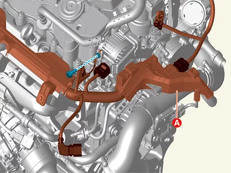
|
Remove the intercooler inlet hose and pipe.
| (1)
|
Remove the connector and main wiring protector (A).
|
Tightening torque :
9.8 - 11.8 N·m (1.0 - 1.2 kgf·m, 7.2 - 8.7 lb·ft)
|
|
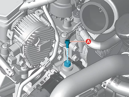
| (2)
|
Remove the intercooler inlet hose bolt (A).
|
Tightening torque
18.6 - 23.5 N·m (1.9 - 2.4 kgf·m, 13.7 - 17.4 lb·ft)
|
|
| (3)
|
Remove the intercooler inlet hose and pipe.
|
Tightening torque :
Clamp bolt : 4.9 - 6.9
N·m (0.5 - 0.7 kgf·m, 3.6 -
5.1 lb·ft, 43.4 - 60.8 lb·in)
|
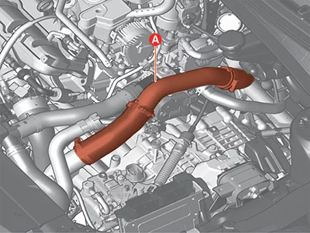
|
|
| 6.
|
Disconnect the filler neck hose (A) after releasing the clamp.
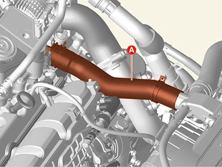
|
| 7.
|
Disconnect the heater hose (A) after releasing the quick connector.
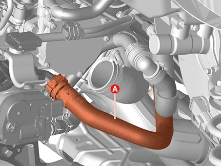
|
| 8.
|
Disconnect the Integrated Thermal Management Module (ITM) connector (A).
|
| 9.
|
Disconnect the oil cooler hose (A) after releasing the clamp.
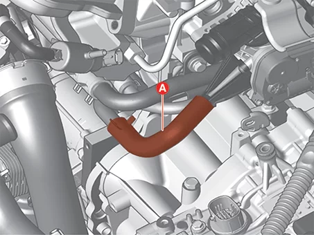
|
| 10.
|
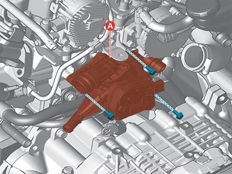
Remove the Integrated Thermal Management Module (ITM) (A) after removing the bolts.
|
Tightening torque :
9.8 - 11.8 N·m (1.0 - 1.2 kgf·m, 7.2 - 8.7 lb·ft)
|
|
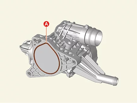
Do not reuse the Integrated Thermal Management Module (ITM) gasket (A).
|
|
Heater Pipe
| 1.
|
Disconnect the battery negative ( - ) terminal.
|
| 2.
|
Drain the coolant.
(Refer to Cooling System - "Coolant")
|
| 3.
|
Remove the air cleaner assembly.
(Refer to Intake and Exhaust System - "Air Cleaner")
|
| 4.
|
Remove the battery and battery tray.
(Refer to Engine Electrical System - "Battery")
|
| 5.
|
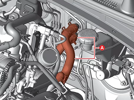
Disconnect the heater hoses (A) after releasing the clamps.
|
| 6.
|
Remove the Integrated Thermal Management Module (ITM).
|
| 7.
|
Remove the drive belt.
(Refer to Drive Belt System - "Drive Belt")
|
| 8.
|
Remove the alternator.
(Refer to Engine Electrical System - "Alternator")
|
| 9.
|
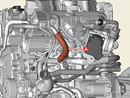
Disconnect the heater pipe hoses (A) after releasing the clamps.
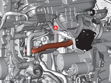
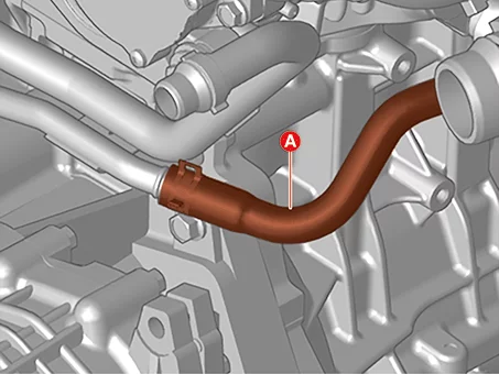
|
| 10.
|
Remove the heater pipe A nuts (A).
|
Tightening torque :
9.8 - 11.8 N·m (1.0 - 1.2 kgf·m, 7.2 - 8.7 lb·ft)
|
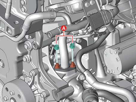
|
| 11.
|
Remove the heater pipe.
| (1)
|
Remove the heater pipe A mounting bolt (A).
|
Tightening torque :
9.8 - 11.8 N·m (1.0 - 1.2 kgf·m, 7.2 - 8.7 lb·ft)
|
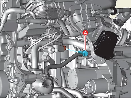
|
| (2)
|
Remove the heater pipe B (A) after removing the bolt.
|
Tightening torque :
14.7 - 21.6 N·m (1.5 - 2.2 kgf·m, 10.8 - 15.9 lb·ft)
|
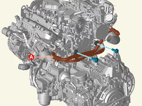
|
| (3)
|
Remove the heater pipe (A).
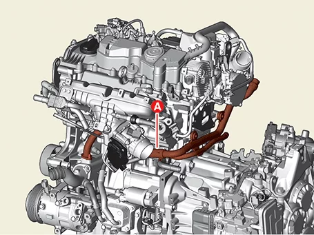
|
|
| 12.
|
Disconnect the oil cooler hose (A) after releasing the clamp.
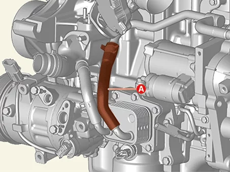
|
| 13.
|
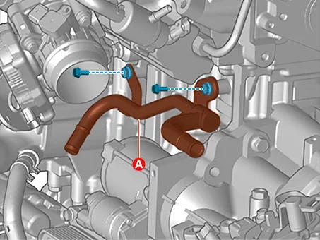
Remove the oil cooler pipe (A) after removing the bolts.
|
Tightening torque :
14.7 - 21.6 N·m (1.5 - 2.2 kgf·m, 10.8 - 15.9 lb·ft)
|
|
•
|
Do not reuse the heater pipe gasket.
|
|
•
|
Assemble the hose so that the hose end pole is attached to the
stopper in the prescribed
position, and keep the clamp in position.
|
|
•
|
Make sure the quick connector installed securely after
installing coolant hose.
|
|
|
| 1.
|
Install in reverse order of removal.
|
Install to the specified torque.
|
|
| 2.
|
Fill with coolant.
(Refer to Cooling System - "Coolant")
|
Be sure to add coolant according to the ITM coolant refill method.
|
|
Water Inlet Fitting Components and Components Location
| Components and Components Location |
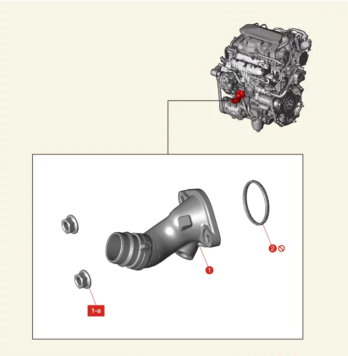
1. Water Inlet
Fitting
1-a. 18.6 - 23.5 N·m (1.9 - 2.4 kgf·m, 13.7 - 17.4 lb·ft)
2. O-Ring
|
Water Inlet Fitting Removal and Installation
| 1.
|
Remove the engine room under cover.
(Refer to Engine and Transaxle Assembly - "Engine Room Under
Cover")
|
| 2.
|
Drain the coolant.
(Refer to Cooling System - "Coolant")
|
| 3.
|
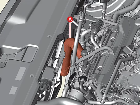
Disconnect the radiator lower hose (A) after releasing the clamp.
|
| 4.
|
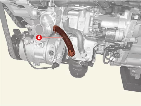
Disconnect the oil cooler hose (A) after releasing the clamp.
|
| 5.
|
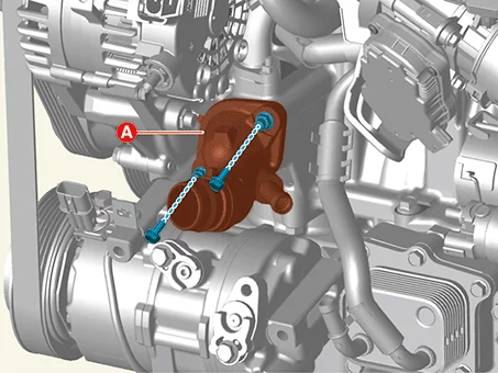
Remove the water inlet fitting (A) after removing the nuts.
|
Tightening torque :
18.6 - 23.5 N·m (1.9 - 2.4 kgf·m, 13.7 - 17.4 lb·ft)
|
|
| 1.
|
Install in reverse order of removal.
|
•
|
Make sure the quick connector installed securely after
installing coolant hose.
|
|
•
|
Assemble the hose so that the hose end pole is attached to the
stopper in the prescribed
position, and keep the clamp in position.
|
|
|
| 2.
|
Fill with coolant.
(Refer to Cooling System - "Coolant")
|
Be sure to add coolant according to the ITM coolant refill method.
|
|
Water Pump Components and Components Location
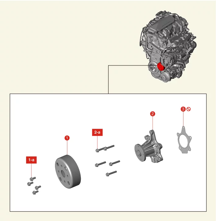
1. Water Pump
Pulley
1-a.
9.8 - 11.8 N·m (1.0 - 1.2 kgf·m, 7.2 - 8.7 lb·ft)
2. Water Pump
2-a. 11.8 - 13.7 N·m (1.2 -
1.4 kgf·m,
8.7 - 10.1 lb·ft)
|
3. Water Pump
Gasket
|
Water Pump Troubleshooting
Coolant leakage
Symptom
|
How to inspect
|
Correction
|
Leak hole
|
Visually check
|
Check leaks after about ten-minute warming up.
|
|
•
|
Replace water pump in case of leak.
|
|
•
|
If there are no leaks, reuse the water pump.
(Do not change the water pump)
|
Evaporation deposits due to the evaporation of microscopic
water vapor or traces of
evaporation of traces of coolant occur even during normal
operation of the water pump.
- Remove the sediment from each pore and recheck for leaks.
|
|
|
Gasket or bolt part leak
|
Check water pump mounting bolt tightness.
|
Tighten the water pump mounting bolts to the specified torque.
|
Check for gasket damage or dust ingress
|
Replace the gasket and clean dust off.
|
Water Pump External Surface Leakage
|
Check the water pump for cracks.
|
Replace water pump in case of cracks.
|
Noise
Symptom
|
How to inspect
|
Correction
|
|
•
|
Mechanical seal high frequency
|
|
Check the use of a stethoscope
|
After starting the engine, check noise with a stethoscope.
|
|
•
|
If there is no noise, reuse the water pump (do not replace it).
|
|
•
|
If there is any noise from the water pump, remove the drive belt and recheck.
(Replace the water pump if noise occurs even after removal)
|
|
Inspection after removing a drive belt
|
After removing a drive belt, check noise again.
|
|
•
|
Drive Reuse of water pump in case of noise from drive
|
|
•
|
If there is no noise, replace the water pump with a new one.
|
|
Inspection after removing a water pump
|
Check water pump body & impeller interference
|
Replace water pump in case of interference
|
Overheat
Symptom
|
How to inspect
|
Correction
|
|
|
Inspection after removing a water pump
|
Corrosion of the impeller wing
|
|
•
|
Poor coolant quality / Maintenance check
|
|
Remove the impeller from the shaft
|
Replace the water pump.
|
Water Pump Removal and Installation
| 1.
|
Remove the engine room under cover.
(Refer to Engine and Transaxle Assembly - "Engine Room Under
Cover")
|
| 2.
|
Drain the coolant.
(Refer to Cooling System - "Coolant")
|
| 3.
|
Remove the drive belt.
(Refer to Drive Belt System - "Drive Belt")
|
| 4.
|
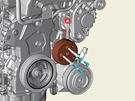
Remove the water pump pulley (A) after removing the bolts.
|
Tightening torque :
9.8 - 11.8 N·m (1.0 - 1.2 kgf·m, 7.2 - 8.7 lb·ft)
|
|
| 5.
|
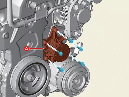
remove the water pump (A) after removing the bolts.
|
Tightening torque :
11.8 - 13.7 N·m (1.2 - 1.4 kgf·m, 8.7 - 10.1 lb·ft)
|
|
| 6.
|
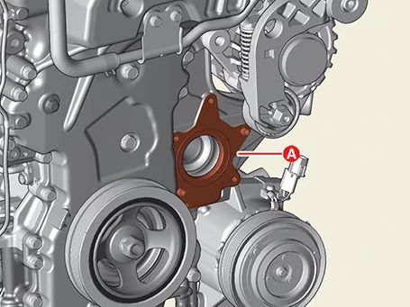
Remove the water pump gasket (A).
|
| 1.
|
Install in reverse order of removal.
|
•
|
Install to the specified torque.
|
|
•
|
Do not reuse the water pump gasket.
|
|
•
|
When installing the water pump, tighten the bolts in the order
shown below.
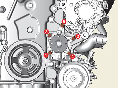
|
|
•
|
Before installing the water pump, remove the cured sealant,
foreign substances, oil,
dust, moisture, etc. inside the bolt hole (A) clearly.
|
|
|
| 2.
|
Fill with coolant.
(Refer to Cooling System - "Coolant")
|
Be sure to add coolant according to the ITM coolant refill method.
|
|
Other information:
Kia K4 (CL4) 2025-2026 Service Manual: Description and Operation
OBD-II review
1. Overview
The California Air Resources Board (CARB) began regulation of On Board Diagnostics (OBD) for vehicles sold in
California beginning with the 1988 model year. The first phase, OBD-I, required monitoring of the fuel metering
system, Exhaust Gas Recirculation (EGR) system and additional emission related components.
Kia K4 (CL4) 2025-2026 Service Manual: General Safety Information and Caution
Precaution (R-134a)
When Handling Refrigerant
1.
R-134a liquid refrigerant is highly volatile. A drop on the skin of your hand could result in
localized
frostbite. When handling the refrigerant, be sure to wear gloves.
2.