Contents:
Charging System Description and Operation
During IG ON, battery voltage is supplied to the wireless power charger system to transmit an output of Max 15
W
to mobile phone.
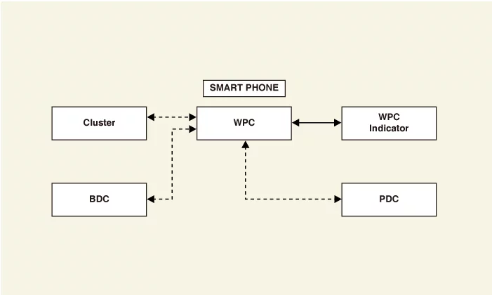
Schematic Diagram
|
–
|
Wireless power charger (WPC) : Negligence of mobile phone, foreign object detection (FOD)
decision.
|
|
–
|
Body domain control unit : Charging stops when LF (FOB key search) is driven
|
|
–
|
Wireless charging indicator : Displays the charging status.
|
|
–
|
Instrument cluster : Alerts about contact with mobile phone.
|
Wireless Power Charger system Major Functions
| 1.
|
Charging Function
| (1)
|
Activation method
| a. |
Close all doors of the vehicle.
|
| b. |
Switch vehicle power to IG ON.
|
| c. |
Place the wireless charging-enabled mobile phone on the tray.
|
|
| (2)
|
Charging status display
Mode
|
Charging LED
display
|
Possible Cause
|
Stand-by for charging
|
LED turned OFF
|
-
|
Charging in process
|
Amber LED turned ON
|
-
|
Charging completed
|
Green LED turned ON
|
-
|
Charging error
|
Amber LED blinks
|
|
–
|
FOD detection : Blinks 10 times and pause for
50 sec → FOD status re-check.
|
|
–
|
High Temp : Blinks 10 times when not charged by
high temperature. LED OFF till
the ERROR message is erased.
|
|
|
|
| 2.
|
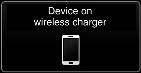
Mobile phone neglect alert function
| (1)
|
Activation method
| a. |
IG OFF when the phone is still charging.
|
| b. |
Check if there is a phone on wireless charging unit.
|
| c. |
Display warning message on the cluster if the phone is left in
the WPC charge pad and the
driver's door is opened or if the phone is left for more than 1
minute. (for about 4 ~ 5
seconds)
|
|
|
| 3.
|
Overheating prevention
| (1)
|
Activation method
| a. |
If the thermistor temperature inside the wireless charging
module rises above (158 °F (70
°C)), charging will stop to protect the mobile phone battery.
|
The amber LED of the charging display lamp
blinks 10 times for 10 seconds.
|
|
| b. |
When the thermistor temperature drops below a certain
temperature (149 °F (65 °C)) the
charging function is restarted.
|
When the charging function is restarted, the
amber LED of the charging display
lamp will be turn on.
|
|
|
|
| 4.
|
Foreign matter detection
| (1)
|
Charging will be disabled if there are coins or other metallic objects between
the wireless
charging unit and the mobile phone.
|
Be careful as touching the foreign matter by hand as it may
cause burns.
|
|
•
|
Foreign matter : All metallic objects such as
coins, clips and precious metals.
|
|
•
|
The amber LED of the charging display lamp
blinks 10 times for 10 seconds, and
then it is turned off for 50 seconds (total 60
seconds).
|
|
•
|
Do it twice (after 50 seconds off, check once
and blink 10 times)
|
|
|
| (2)
|
If a foreign substance is detected and the charging of the mobile phone is
stopped, the charging
resumes after about 60 seconds when the foreign substance is removed.
|
When the charging function is restarted, the amber LED of the
charging display lamp will
be turn on.
|
|
|
| 5.
|
Body domain control unit LF frequency interference prevention function
To avoid interference between the wireless charging frequency and the body domain control unit
frequency
band.
| (1)
|
Wireless charging is stopped when the door is open or the body domain control
unit is in LF
operation (smart key search).
e.g. Wireless charging function is stopped if the driver carries the smart key
out of the vehicle
during IG ON.
|
Charging will stop and the amber LED of the charging display
lamp will turn off.
|
|
| (2)
|
When the BDC unit LF operation is finished, it operates normally.
|
|
| 6.
|
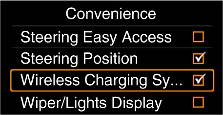
Turn the wireless charging function ON/OFF with USM.
|
Wireless Power Charger (WPC) System Protection
Item
|
Condition
|
State
|
Protects against low/high voltage
|
Protects and stops charging under 8.5 V and over 16.5 V
|
LED OFF
(Stops operation)
|
Charges between 9 - 16 volts
|
Protects against reverse voltage
|
Protects and stops charging in case of reverse voltage
|
LED OFF
(Stops operation)
|
Protects against overcurrent
|
Protects and stops charging in case of detecting 4 amps
|
Amber LED blinks
|
Protects against overheating
|
Protects and stops charging in case of detecting 70°C (158 °F) by internal
temperature
sensor of wireless charging module
|
Amber LED blinks
|
Resumes under 65°C (149°F)
|
Foreign substances
(Coins, clips, precious metals, etc.)
|
Protects and stops charging in case of detecting foreign matter (overheating
prevention)
|
Amber LED blinks
|
Prevents frequency interference
|
Protects and stops charging by activating IBU in case door or tailgate is
open
|
LED OFF
(Stops operation)
|
Resumes in 3.5 seconds after all doors and tailgate are closed and IBU
operation is
completed
|
Mobile phone neglect alert function
|
In case of smart phone on the charging pad when opening the door after IG
OFF.
|
Displays warning message on the instrument panel (for about 4 - 5
seconds)
|
Charging System On Vehicle Inspection
| 1.
|
The wireless charging unit can quickly diagnosed for problems with the KDS. (Refer to "DTC
guide")
| (1)
|
Self diagnosis : Inspect the Diagnostic Trouble Code (DTC) with the KDS.
(Refer to DTC guide when fault code is found)
|
Refer to the KDS screen for operating conditions and details.
|
|
|
Charging System Removal and Installation
|
The indication below represents the location of a clip or fastener.

|
Wireless Power Charger (WPC)
| 1.
|
Remove the WPC.
(Refer to Floor Console - "Floor Console Assembly")
|
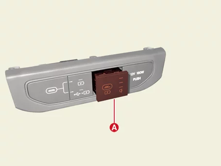
USB Charger
| 1.
|
Remove the floor console bezel.
(Refer to Floor Console - "Floor Console Assembly")
|
| 2.
|
Remove the USB charger (A).
|
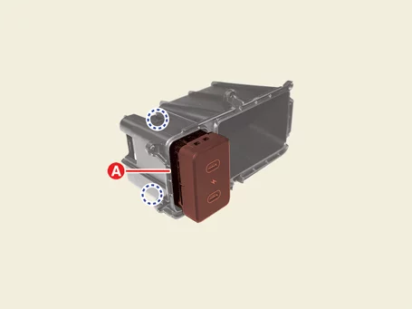
| Floor Console Rear Cover Side |
| 1.
|
Remove the floor console storage box.
(Refer to Floor Console - "Floor Console Assembly")
|
| 2.
|
Remove the USB charger (A).
|
| 1.
|
Install in the reverse order of removal.
|
| 2.
|
Perform Over The Air (OTA) controller S/W update with KDS. [Wireless
Power Charger (WPC) only]
(Refer to Security & Vehicle Ignition System - "Over The
Air
(OTA)")
|
Multifunction Switch Specifications
Item
|
Resistance (Ω)
|
Switch
|
Switch Position
|
Light switch
|
OFF
|
656.2 - 703.8
|
AUTO
|
1,621.2 - 1,738.8
|
Tail lamp
|
5,384.7 - 5,775.3
|
Low beam
|
∞
|
Head lamp back up switch
|
OFF
|
∞
|
ON
|
188.17 - 201.82
|
Head lamp high
|
OFF
|
∞
|
Passing
|
878.15 - 941.85
|
Dimmer
|
2,808.15 - 3,011.85
|
Turn signal switch (LH)
|
OFF
|
∞
|
Lane Change
|
878.15 - 941.85
|
Full turn
|
2,808.15 - 3,011.85
|
Turn signal switch (RH)
|
OFF
|
∞
|
Lane Change
|
878.15 - 941.85
|
Full turn
|
2,808.15 - 3,011.85
|
Fog lamp switch
|
Off
|
∞
|
Front fog lamp
|
878.15 - 941.85
|
Rear fog lamp
|
2,808.15 - 3,011.85
|
Front wiper switch
|
Mist
|
318.45 - 341.55
|
OFF
|
∞
|
Auto
|
772 - 828
|
Low
|
1737 - 1863
|
High
|
5,500.5 - 5,899.5
|
Wiper intermittent volume
|
Volume 1
|
318.45 - 341.55
|
Volume 2
|
665.85 - 714.15
|
Volume 3
|
1,264.15 - 1,355.85
|
Volume 4
|
2,518.65 - 2,701.35
|
Volume 5
|
7,054.15 - 1,565.85
|
Wiper low back up switch
|
OFF
|
∞
|
ON
|
188.17 - 201.82
|
Rear wiper switch
|
OFF
|
∞
|
LOW
|
878.15 - 941.85
|
HIGH
|
2,808.15 - 3,011.85
|
Multifunction Switch On Vehicle Inspection
| 1.
|
The multifunction switch can quickly diagnosed for problems with the KDS. (Refer to "DTC
guide")
| (1)
|
Self diagnosis : Inspect the Diagnostic Trouble Code (DTC) with the KDS.
(Refer to DTC guide when fault code is found)
|
|
Refer to the KDS screen for operating conditions and details.
|
|
Multifunction Switch Removal and Installation
| 1.
|
Remove the steering wheel.
(Refer to Steering System - "Steering Wheel")
|
| 2.
|
Remove the steering column shroud panel.
(Refer to Crash Pad - "Steering Column Shroud Panel")
|
| 3.
|
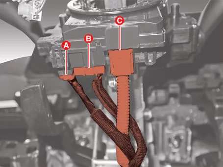
Disconnect the connectors (A, B, C).
A : Multifunction switch connector
B : Steering wheel remote controller connector
C : Drive Airbag (DAB) connector
|
| 4.
|
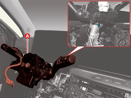
Remove the multifunction switch assembly (A) after loosening the bolt.
|
Tightening torque :
4.5 - 6.5 N·m (0.46 - 0.66 kgf·m, 3.3 - 4.8 lb·ft, 39.9 - 57.3 lb·in)
|
|
| 1.
|
Install in the reverse order of removal.
|
Multifunction Switch Inspection
| 1.
|
Check for continuity between the terminals in each switch position as shown below.
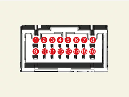
Switch
|
Switch Position
|
Switch Terminal
|
Resistance (Ω)
|
Light switch
|
OFF
|
10 - 4
|
656.2 - 703.8
|
AUTO
|
1,621.2 - 1,738.8
|
Tail lamp
|
5,384.7 - 5,775.3
|
Low beam
|
∞
|
Head lamp back up switch
|
OFF
|
2 - 4
|
∞
|
ON
|
188.17 - 201.82
|
Head lamp high
|
OFF
|
13 - 4
|
∞
|
Passing
|
878.15 - 941.85
|
Dimmer
|
2,808.15 - 3,011.85
|
Turn signal switch (LH)
|
OFF
|
14 - 4
|
∞
|
Lane Change
|
878.15 - 941.85
|
Full turn
|
2,808.15 - 3,011.85
|
Turn signal switch (RH)
|
OFF
|
15 - 4
|
∞
|
Lane Change
|
878.15 - 941.85
|
Full turn
|
2,808.15 - 3,011.85
|
Fog lamp switch
|
Off
|
12 - 4
|
∞
|
Front fog lamp
|
878.15 - 941.85
|
Rear fog lamp
|
2,808.15 - 3,011.85
|
Front wiper switch
|
Mist
|
6 - 4
|
318.45 - 341.55
|
OFF
|
∞
|
Auto
|
772 - 828
|
Low
|
1737 - 1863
|
High
|
5,500.5 - 5,899.5
|
Wiper intermittent volume
|
Volume 1
|
3 - 4
|
318.45 - 341.55
|
Volume 2
|
665.85 - 714.15
|
Volume 3
|
1,264.15 - 1,355.85
|
Volume 4
|
2,518.65 - 2,701.35
|
Volume 5
|
7,054.15 - 1,565.85
|
Ground
|
-
|
B+
|
-
|
Wiper low back up switch
|
OFF
|
7 - 8
|
∞
|
ON
|
188.17 - 201.82
|
Front washer switch
|
OFF
|
9 - 8
|
-
|
ON
|
-
|
Rear washer switch
|
OFF
|
1 - 8
|
-
|
ON
|
-
|
Rear wiper switch
|
OFF
|
11 - 4
|
∞
|
LOW
|
878.15 - 941.85
|
HIGH
|
2,808.15 - 3,011.85
|
Ground
|
-
|
|