Contents:
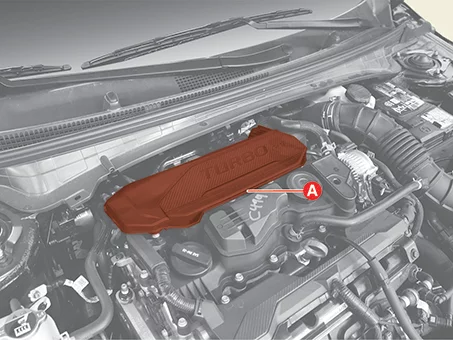
Engine Cover Removal and Installation
| 1.
|
Remove the engine cover (A).
|
| 1.
|
Install in reverse order of removal.
|
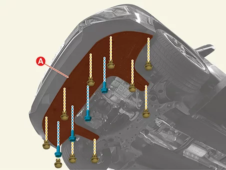
Engine Room Under Cover Removal and Installation
| 1.
|
Remove the engine room under cover (A) after removing the fasteners and bolts.
|
Tightening torque :
7.8 - 11.8 N·m (0.8 - 1.2 kgf·m, 5.8 - 8.7 lb·ft)
|
|
| 1.
|
Install in reverse order of removal.
|
Install to the specified torque.
|
|
Engine Mounting Components and Components Location
| Components and Components Location |
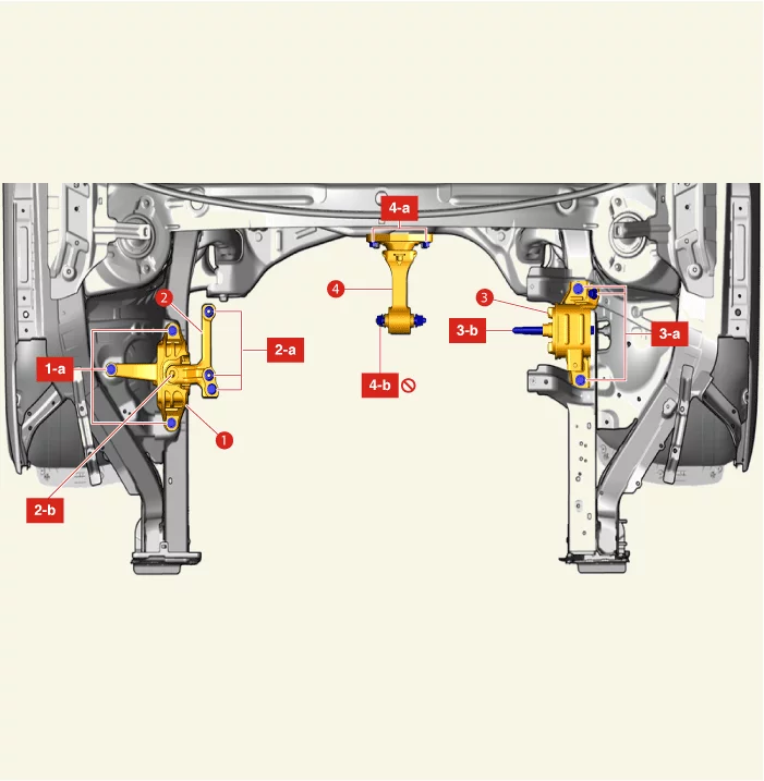
1. Engine Mounting Bracket
1-a. 49.0 - 63.7
N·m
(5.0 - 6.5 kgf·m, 36.2 - 47.0 lb·ft)
2. Engine Mounting Support Bracket.
2-a. 58.8 - 73.5 N·m
(6.0 - 7.5
kgf·m, 43.4 - 54.2 lb·ft)
2-b. 88.3 - 107.9 N·m (9.0 - 11.0 kgf·m, 65.1 - 79.6 lb·ft)
3.
Transaxle
Mounting Bracket
3-a. 49.0 - 63.7 N·m (5.0 - 6.5 kgf·m, 36.2 - 47.0 lb·ft)
3-b. 88.3 - 107.9
N·m (9.0 -
11.0 kgf·m, 65.1 - 79.6 lb·ft)
|
4. Roll Rod Bracket
4-a. 49.0 - 63.7 N·m
(5.0 - 6.5
kgf·m, 36.2 - 47.0 lb·ft)
4-b. 107.9 - 127.5 N·m (11.0 - 13.0 kgf·m, 79.6 - 94.0 lb·ft)
|
Engine Mounting Removal and Installation
Engine Mounting Bracket
| 1.
|
Remove the engine room under cover.
(Refer to Engine and Transaxle Assembly - "Engine Room Under
Cover")
|
| 2.
|
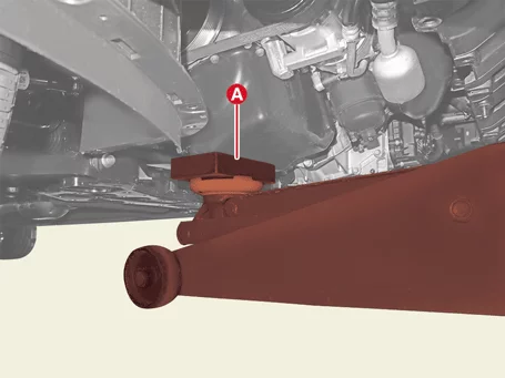
Install the jack (A) to the edge of oil pan to support the engine.
|
Put a rubber pad between the lower oil pan and the jack to prevent damage to
the oil pan.
|
|
| 3.
|
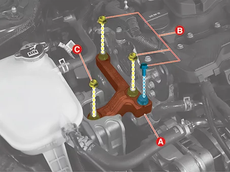
Remove the engine mounting support bracket (A) after removing the bolt and nuts (B, C).
|
Tightening torque :
B : 58.8 - 73.5 N·m (6.0 - 7.5 kgf·m, 43.4 - 54.2 lb·ft)
C : 88.3 - 107.9 N·m (9.0 - 11.0 kgf·m, 65.1 - 79.6 lb·ft)
|
|
| 4.
|
Remove the reservoir tank.
(Refer to Cooling System - "Reservoir Tank")
|
| 5.
|
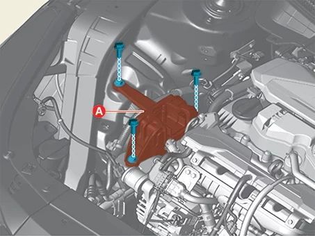
Remove the engine mounting bracket (A) after removing the bolts.
|
Tightening torque :
49.0 - 63.7 N·m (5.0 - 6.5 kgf·m, 36.2 - 47.0 lb·ft)
|
|
Transaxle Mounting Bracket
| 1.
|
Remove the air cleaner assembly.
(Refer to Intake and Exhaust System – "Air Cleaner")
|
| 2.
|
Remove the battery and battery tray.
(Refer to Engine Electrical System - "Battery")
|
| 3.
|
Remove the engine room under cover.
(Refer to Engine and Transaxle Assembly - "Engine Room Under
Cover")
|
| 4.
|
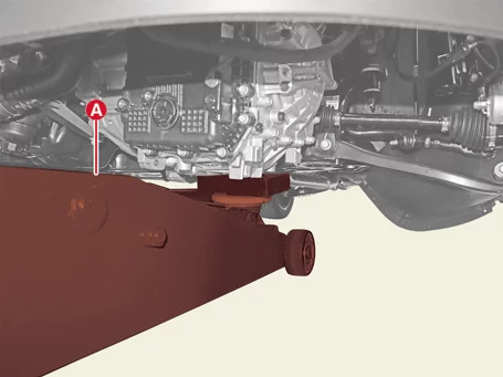
Install the jack (A) under the transaxle to support.
|
Put a rubber pad between the transaxle and the jack to prevent damage to the
transaxle.
|
|
| 5.
|
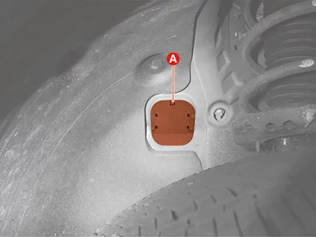
Remove the transaxle mounting side pannel packing (A).
|
| 6.
|
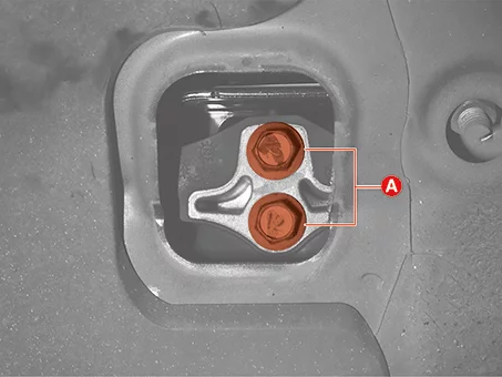
Remove the transaxle mounting fastening bolt (A).
|
Tightening torque :
88.3 - 107.9 N·m (9.0 - 11.0 kgf·m, 65.1 - 79.6 lb·ft)
|
|
•
|
Do not reuse the bolt (A).
|
|
•
|
When tighten the transaxle mounting bolts (A), tighten the
lower bolt and then the upper
bolt.
|
|
|
| 7.
|
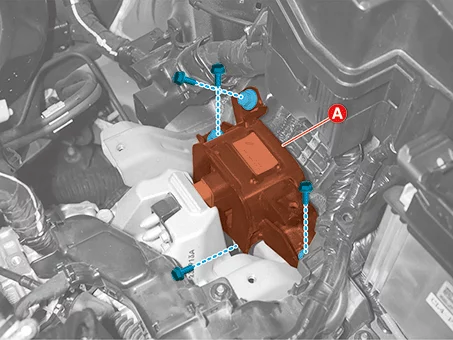
Remove the transaxle mounting bracket (A), after removing the bolts and nut.
|
Tightening torque :
49.0 - 63.7 N·m (5.0 - 6.5 kgf·m, 36.2 - 47.0 lb·ft)
|
|
Roll Rod Bracket
| 1.
|
Remove the engine room under cover.
(Refer to Engine and Transaxle Assembly - "Engine Room Under
Cover")
|
| 2.
|
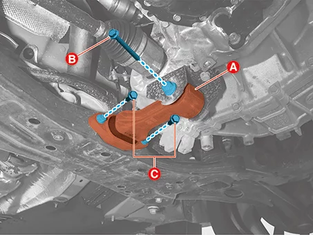
Remove the roll rod bracket (A) after removing the bolts.
|
Tightening torque
B : 107.9 - 127.5 N·m (11.0 - 13.0 kgf·m, 79.6 - 94.0 lb·ft)
C : 49.0 - 63.7 N·m (5.0 - 6.5 kgf·m,
36.2 - 47.0 lb·ft)
|
|
•
|
Do not reuse the roll rod bracket bolt (B).
|
|
|
| 3.
|
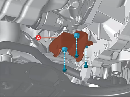
Remove the roll rod mounting support bracket (A) after removing the bolts.
|
Tightening torque :
49.0 - 68.6 N·m (5.0 - 7.0 kgf·m, 36.2 - 50.6 lb·ft)
|
|
| 1.
|
Install in reverse order of removal.
|
Install to the specified torque.
|
|
Engine and Transaxle Assembly Removal
|
•
|
This video was created using 3D graphics to help understand the vehicle
maintenance manual.
|
|
•
|
There may be some differences from actual vehicles.
|
|
•
|
The location and repair procedures of the parts may vary depending on vehicle
model, model year,
region, and specifications.
|
|
•
|
Check the KDS Guide for detailed information on how to use the KDS.
|
|
•
|
Check the manual for detailed maintenance procedures.
|
|
•
|
Unauthorized reproduction, distribution, or sharing of this video is
prohibited.
|
|
Engine and Transaxle Assembly Removal
(Click to play)

Video: Engine and Transaxle Assembly
Removal
|
•
|
Use a fender cover to protect the painted surface.
|
|
•
|
Be careful not to damage the connector when disconnecting.
|
|
|
Mark all wiring and hoses to prevent incorrect connections.
|
| 1.
|
Release the residual pressure in fuel line.
(Refer to Fuel Delivery System - "Release Residual Pressure in
Fuel
Line")
|
| 2.
|
Remove the engine cover.
(Refer to Engine and Transaxle Assembly - "Engine
Cover")
|
| 3.
|
Remove the air cleaner assembly.
(Refer to Intake and Exhaust System - "Air Cleaner")
|
| 4.
|
Remove the battery and battery tray.
(Refer to Engine Electrical System - "Battery")
|
| 5.
|
Remove the engine room under cover.
(Refer to Engine and Transaxle Assembly - "Engine Room Under
Cover")
|
| 6.
|
Drain the engine coolant.
(Refer to Cooling System - "Coolant")
|
| 7.
|
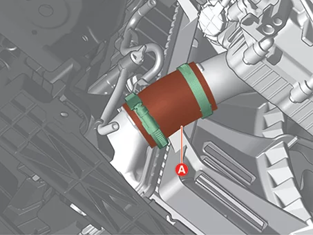
Disconnect the intercooler inlet hose (A) after releasing the clamp.
|
| 8.
|
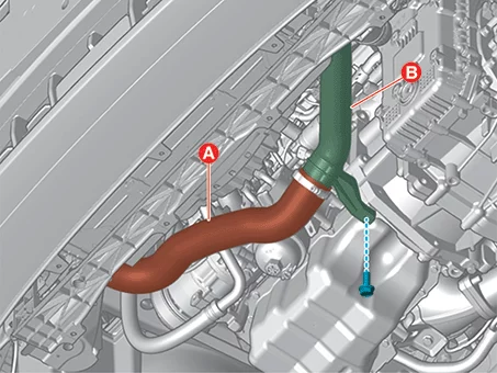
Disconnect the intercooler hose (A, B) after removing the bolt.
|
Tightening torque :
18.6 - 23.5 N·m (1.9 - 2.4 kgf·m, 13.7 - 17.4 lb·ft)
|
|
| 9.
|
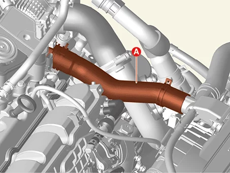
Disconnect the filler neck hose (A) after releasing the clamp.
|
| 10.
|
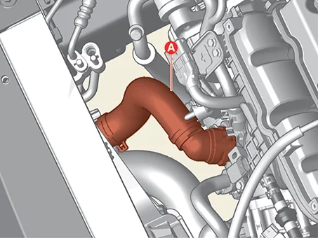
Disconnect the radiator lower hose (A) after releasing the quick connector.
|
| 11.
|
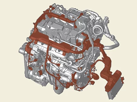
Remove the engine main wiring connector, harness clamp and wiring protector from the engine.
|
| 12.
|
Disconnect the wiring harness connector and the control cable hose connected to the transaxle.
(Refer to Automatic Transaxle System - "Automatic
Transaxle")
|
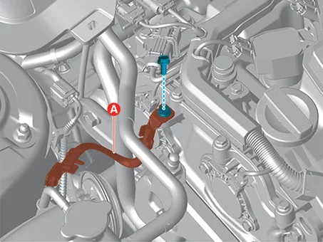
| 13.
|
Disconnect the engine ground cable (A) after removing the bolt.
|
Tightening torque :
10.8 - 13.7 N·m (1.1 - 1.4 kgf·m, 8.0 - 10.1 lb·ft)
|
|
| 14.
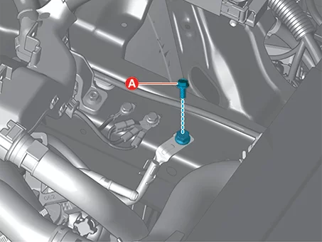
|
Remove the transaxle ground cable bolt (A).
|
Tightening torque :
26.5 - 32.4 N·m (2.7 - 3.3 kgf·m, 19.5 - 23.9 lb·ft)
|
|
| 15.
|
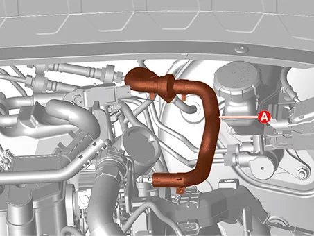
Disconnect the brake vacuum hose (A) after releasing the clamp.
|
| 16.
|
Disconnect the fuel hose (B) and Purge Control Solenoid Valve (PCSV) hose (A).
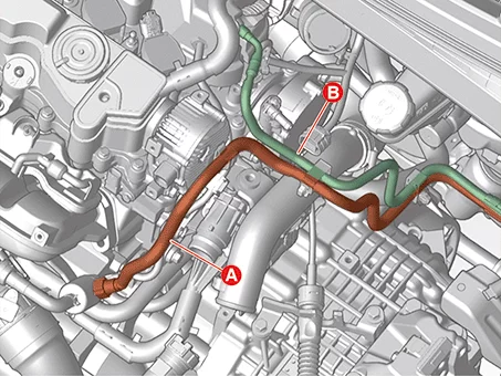
|
| 17.
|
Disconnect the heater hoses (A) after releasing the quick connector.
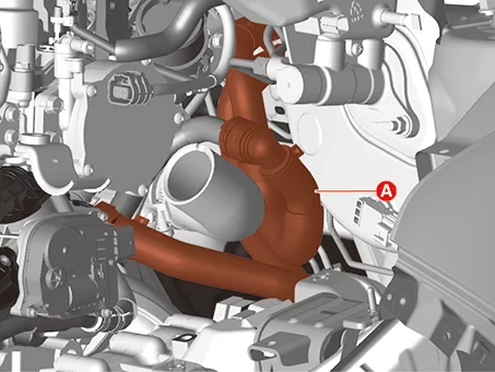
|
| 18.
|
Disconnect the reservoir water hose (A) after releasing the clamp.
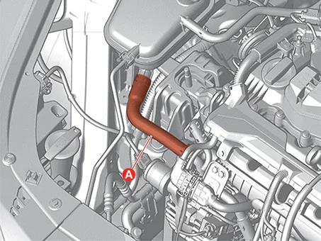
|
| 19.
|
Disconnect the reservoir tank hose (A) after releasing the clamp.
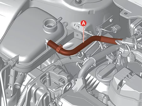
|
| 20.
|
Disconnect the A/C compressor high pressure pipe and low pressure pipe.
(Refer to Heating, Ventilation and Air Conditioning -
"Compressor")
|
| 21.
|
Remove the front muffler.
(Refer to Intake and Exhaust System - "Muffler")
|
| 22.
|
Remove the roll rod bracket (A) after removing the bolts.
|
Tightening torque
B : 107.9 - 127.5 N·m (11.0 - 13.0 kgf·m, 79.6 - 94.0 lb·ft)
C : 49.0 - 63.7 N·m (5.0 - 6.5 kgf·m,
36.2 - 47.0 lb·ft)
|
|
•
|
Do not reuse the roll rod bracket bolt (B).
|
|
|
| 23.
|
Remove the roll rod mounting support bracket (A), after removing the bolts.
|
Tightening torque :
49.0 - 68.6 N·m (5.0 - 7.0 kgf·m, 36.2 - 50.6 lb·ft)
|
|
| 24.
|
Remove the front sub-frame.
(Refer to Suspension System - "Front Sub Frame")
|
| 25.
|
Remove the drive shaft from the front axle.
(Refer to Driveshaft and Axle - "Front Driveshaft")
|
| 26.
|
Lift tables are used to securely support the engine and transaxle assemblies.
|
| 27.
|
Remove the engine mounting support bracket (A) after removing the bolt and nuts (B, C).
|
Tightening torque :
B : 58.8 - 73.5 N·m (6.0 - 7.5 kgf·m, 43.4 - 54.2 lb·ft)
C : 88.3 - 107.9 N·m (9.0 - 11.0 kgf·m, 65.1 - 79.6 lb·ft)
|
|
| 28.
|
Remove the transaxle mounting side pannel packing (A).
|
| 29.
|
Remove the transaxle mounting bolts (A).
|
Tightening torque :
88.3 - 107.9 N·m (9.0 - 11.0 kgf·m, 65.1 - 79.6 lb·ft)
|
|
•
|
Do not reuse the bolt (A).
|
|
•
|
When tighten the transaxle mounting bolts (A), tighten the
lower bolt and then the upper
bolt.
|
|
|
| 30.
|
Remove the engine and transaxle assembly by lifting vehicle.
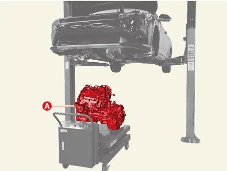
|
•
|
Before removing the engine and transaxle assembly, make sure
hoses and wire connectors
are disconnected.
|
|
•
|
When removing the engine and transaxle assembly, be careful not
to damage any surrounding
parts or body components.
|
|
|
Engine and Transaxle Assembly Installation
| 1.
|
Install in reverse order of removal.
|
•
|
Install the Engine And Transaxle Assembly to the specified
torque.
|
|
•
|
When installing the quick connector hose, make sure it is
properly installed.
|
|
|
| 2.
|
Fill with coolant.
(Refer to Cooling System - "Coolant")
|
Be sure to add coolant according to the ITM coolant refill method.
|
|
| 3.
|
After cleaning the battery terminals and cable terminals with sandpaper, assemble them
|
| 4.
|
Check the alignment.
(Refer to Suspension System - "Alignment")
|
Other information:
Kia K4 (CL4) 2025-2026 Service Manual: Highway Driving Assist settings
Driver Assistance
Driving Convenience
Highway Driving Assist
While the vehicle is powered ON, access your Kia K4 infotainment system and tap Setup > Vehicle > Driver Assistance > Driving Convenience to configure the customized options for each driver-assist function.
Kia K4 (CL4) 2025-2026 Service Manual: Smart Cruise Control display and control
You can conveniently monitor the current status and operational state of the Smart Cruise Control (SCC) system by navigating to the "Driving Assist" view on your Kia K4 instrument cluster. For further details on customizing these views, please refer to your owner's manual section on LCD display modes.
The Kia K4 instrument cluster provides clear visual feedback regarding the SCC status through various indicators:
When the system is active and operating:
Shows whether a lead vehicle is detected ahead and highlights the current vehicle-to-vehicle distance level setting.