Contents:
Air Cleaner Removal and Installation
Air cleaner assembly
| 1.
|
Disconnect the battery negative ( - ) terminal.
|
| 2.
|
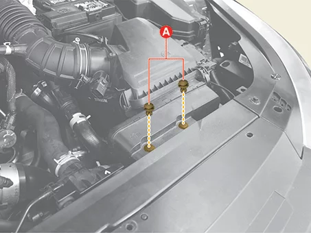
Remove the extension air duct fasteners (A).
|
| 3.
|
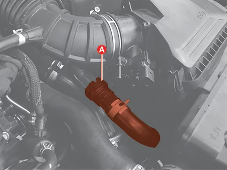
Disconnect the Recirculation Control Valve (RCV) hose (A).
|
| 4.
|
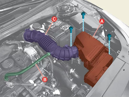
Remove the air cleaner assembly (A) after removing the bolt.
| (1)
|
Disconnect the fresh air hose (B) after releasing the clamp.
|
| (2)
|
Disconnect the air intake hose (C) after releasing the clamp.
|
| (3)
|
Remove the air cleaner assembly (A) after removing the bolts.
|
Tightening torque :
3.9 - 5.9 N·m (0.4 - 0.6 kgf·m , 2.9 - 4.3 lb·ft, 34.7 - 52.1
lb·in)
|
|
|
Extension Air Duct
| 1.
|
Remove the air cleaner assembly.
|
| 2.
|
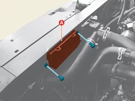
Remove the extension air duct (A) after removing the bolts.
|
Tightening torque :
3.9 - 5.9 N·m (0.4 - 0.6 kgf·m , 2.9 - 4.3 lb·ft, 34.7 - 52.1 lb·in)
|
|
Air cleaner filter replacement
| 1.
|
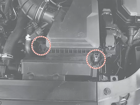
Open the air cleaner filter cover after releasing the clips.
|
| 2.
|
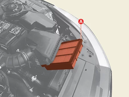
Replace the air cleaner filter (A) with a new one.
|
If there are foreign matters inside the air cleaner assembly, replace the
filter after cleaning
the inside.
|
|
| 1.
|
Install in reverse order of removal.
|
Install to the specified torque.
|
|
| Air cleaner filter replacement |
| 1.
|
Close the air cleaner cover by hooking the clamps.
|
Intake Manifold Components and Components Location
| Components and Components Location |
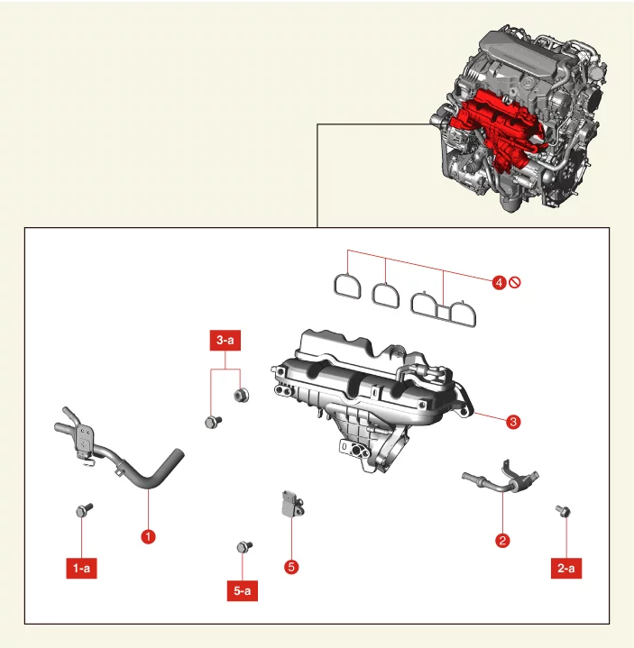
1. Water Return
Pipe
1-a.
9.8 - 11.8 N·m (1.0 - 1.2 kgf·m, 7.2 - 8.7 lb·ft)
2. Purge Control Solenoid Valve (PCSV)
2-a.
9.8 -
11.8 N·m (1.0 - 1.2 kgf·m, 7.2 - 8.7 lb·ft)
3. Intake Manifold
3-a. 18.6 - 23.5 N·m (1.9 -
2.4 kgf·m,
13.7 - 17.4 lb·ft)
|
4. Intake Manifold
Gasket
5. Manifold Absolute Pressure Sensor & Intake Air Temperature Sensor (MAPS &
IATS)
5-a.
9.8 - 11.8 N·m (1.0 - 1.2 kgf·m, 7.2 - 8.7 lb·ft)
|
Intake Manifold Removal and Installation
|
•
|
This video was created using 3D graphics to help understand the vehicle
maintenance manual.
|
|
•
|
There may be some differences from actual vehicles.
|
|
•
|
The location and repair procedures of the parts may vary depending on vehicle
model, model year,
region, and specifications.
|
|
•
|
Check the KDS Guide for detailed information on how to use the KDS.
|
|
•
|
Check the manual for detailed maintenance procedures.
|
|
•
|
Unauthorized reproduction, distribution, or sharing of this video is
prohibited.
|
|
Intake Manifold Removal
(Click to play)

Video: Intake Manifold Removal
| 1.
|
Remove the engine cover.
(Refer to Engine and Transaxle Assembly - "Engine
Cover")
|
| 2.
|
Remove the air cleaner assembly.
(Refer to Intake and Exhaust System - "Air Cleaner")
|
| 3.
|
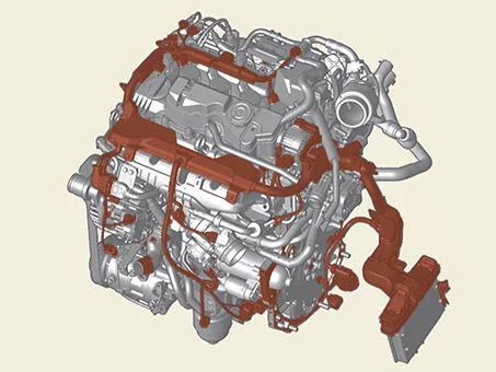
Disconnect the engine wiring connector and harness clamp and disconnect the wiring from intake
manifold.
|
| 4.
|
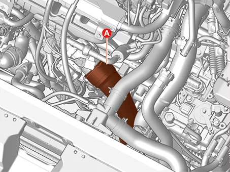
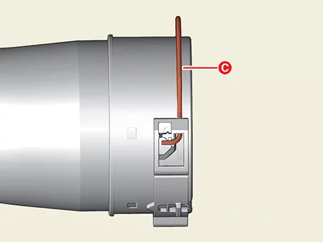
Disconnect the intercooler inlet pipe (A) after releasing the quick connector.
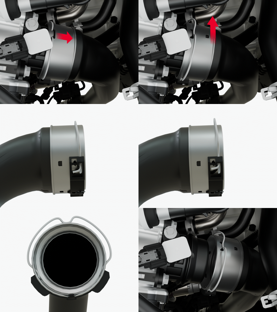
| 1) |
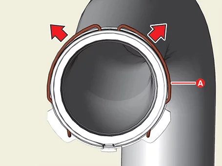
When disconnect the intercooler outlet hose, pull out the quick
connector clamp (A) in
the direction of the arrow as shown below.
|
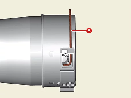
| 2) |
Move the quick connector clamp from position (B) to position
(C) as shown below and pull
out the quick connector hose.
|
|
|
| 5.
|
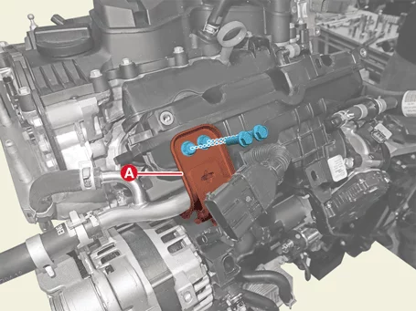
Separate the return hose and pipe bracket bolts (A).
|
Tightening torque :
9.8 - 11.8 N·m (1.0 - 1.2 kgf·m, 7.2 - 8.7 lb·ft)
|
|
| 6.
|
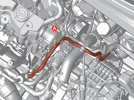
Disconnect the Purge Control Solenoid Valve (PCSV) hose (A).
|
| 7.
|
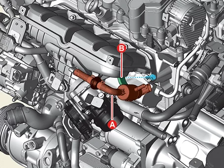
Remove the Purge Control Solenoid Valve (PCSV) (A) and bracket (B) after removing the bolt.
|
Tightening torque :
9.8 - 11.8 N·m (1.0 - 1.2 kgf·m, 7.2 - 8.7 lb·ft)
|
|
| 8.
|
Remove the MAPS & IATS.
(Refer to Engine Control / Fuel System - "Manifold Absolute
Pressure
Sensor (MAPS) & Intake Air Temperature Sensor (IATS)")
|
| 9.
|
Remove the Electronic Throttle Control (ETC) module.
(Refer to Engine Control / Fuel System - "ETC (Electronic
Throttle
Control module")
|
| 10.
|
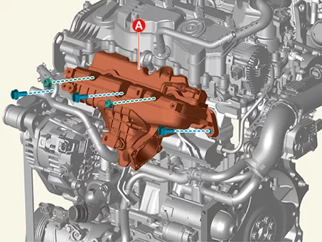
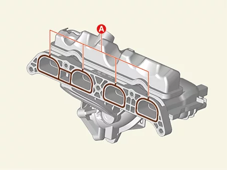
Remove the intake manifold (A) with the gasket after removing the bolts and nuts.
|
Tightening torque :
18.6 - 23.5 N·m (1.9 - 2.4 kgf·m, 13.7 - 17.4 lb·ft)
|
|
Do not reuse the intake manifold gasket.
|
|
| 1.
|
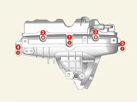
Install in reverse order of removal.
|
When installing, pre-tighten the bolts and nuts in the order shown in the
figure and then fully
tighten them to the specified torque.
|
|
Turbo Manifold Components and Components Location
| Components and Components Location |
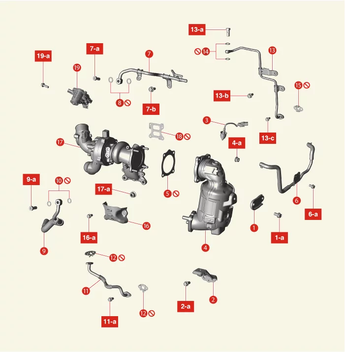
1. Warm-Up
Catalytic
Converter (WCC) Upper Bracket
1-a. 39.2 - 44.1 N·m (4.0 - 4.5 kgf·m, 28.9 - 32.5 lb·ft)
2.
Warm-Up
Catalytic Converter (WCC) Lower Bracket
2-a. 49.0 - 53.9 N·m (5.0 - 5.5 kgf·m, 36.2 - 39.8 lb·ft)
3.
Front Heated Oxygen Sensor (HO2S).
4. Warm-Up Catalytic Converter (WCC)
4-a. 35.3 - 41.2 N·m
(3.6 - 4.2
kgf·m, 26.0 - 30.4 lb·ft)
5. Warm-Up Catalytic Converter (WCC) Gasket
6. Turbocharger Coolant
Hose and
Pipe
6-a. 9.8 - 11.8 N·m (1.0 - 1.2 kgf·m, 7.2 - 8.7 lb·ft)
7. Turbocharger Water Outlet
Pipe
7-a.
34.3 - 39.2 N·m (3.5 - 4.0 kgf·m, 25.3 - 28.9 lb·ft)
7-b. 9.8 - 11.8 N·m (1.0 - 1.2 kgf·m, 7.2 -
8.7 lb·ft)
8. Turbocharger Water Outlet Pipe Eye Bolt Gasket
9. Turbocharger Water Inlet Hose &
Pipe
9-a.
34.3 - 39.2 N·m (3.5 - 4.0 kgf·m, 25.3 - 28.9 lb·ft)
10. Turbocharger Water Inlet Hose & Pipe
Eye Bolt
Gasket
|
11. Oil Drain
Pipe
11-a. 9.8 - 11.8 N·m (1.0 - 1.2 kgf·m, 7.2 - 8.7 lb·ft)
12. Oil Drain Pipe Gasket
13.
Oil Feed
Pipe
13-a. 16.7 - 21.6 N·m (1.7 - 2.2 kgf·m, 12.3 - 15.9 lb·ft)
13-b. 18.6 - 23.5 N·m (1.9 -
2.4 kgf·m,
13.7 - 17.4 lb·ft)
13-c. 9.8 - 11.8 N·m (1.0 - 1.2 kgf·m, 7.2 - 8.7 lb·ft)
14. Oil Feed Pipe
Eye Bolt
Gasket
15. Oil Feed Pipe Gasket
16. Exhaust Manifold Heat Protector
16-a. 9.8 - 11.8 N·m
(1.0 - 1.2
kgf·m, 7.2 - 8.7 lb·ft)
17. Turbo Manifold
17-a. 49.0 - 53.9 N·m (5.0 - 5.5 kgf·m, 36.2 -
39.8 lb·ft)
18. Turbo Manifold Gasket
19. Electric Waste Gate Actuator (EWGA)
19-a. 9.8 - 11.8 N·m
(1.0 - 1.2
kgf·m, 7.2 - 8.7 lb·ft)
|
Turbo Manifold Removal and Installation
|
•
|
This video was created using 3D graphics to help understand the vehicle
maintenance manual.
|
|
•
|
There may be some differences from actual vehicles.
|
|
•
|
The location and repair procedures of the parts may vary depending on vehicle
model, model year,
region, and specifications.
|
|
•
|
Check the KDS Guide for detailed information on how to use the KDS.
|
|
•
|
Check the manual for detailed maintenance procedures.
|
|
•
|
Unauthorized reproduction, distribution, or sharing of this video is
prohibited.
|
|
Turbo Manifold Removal
(Click to play)
Video: Turbo Manifold Removal
|
Wait until cooling the engine for preventing the scalding by high temperature from the exhaust
system.
|
|
•
|
Use a fender cover to protect the painted surface.
|
|
•
|
When handling a metal gasket, take care not to fold the gasket or damage the
contact surface of
the gasket.
|
|
•
|
To avoid damage, disconnect the wiring connectors carefully.
|
|
•
|
The existing gasket should be replaced with a new one.
|
|
| 1.
|
Disconnect the battery negative ( - ) terminal.
|
| 2.
|
Remove the engine cover.
(Refer to Engine and Transaxle Assembly - "Engine
Cover")
|
| 3.
|
Remove the air cleaner assembly.
(Refer to Intake and Exhaust System - "Air Cleaner")
|
| 4.
|
Remove the engine room under cover.
(Refer to Engine and Transaxle Assembly - "Engine Room Under
Cover")
|
| 5.
|
Drain the coolant.
(Refer to Cooling System - "Coolant")
|
| 6.
|
Remove the front muffler.
(Refer to Intake and Exhaust System - "Muffler")
|
| 7.
|
Remove the Warm-up Catalytic Converter (WCC).
(Refer to Emission Control System - "Catalytic
Converter")
|
| 8.
|
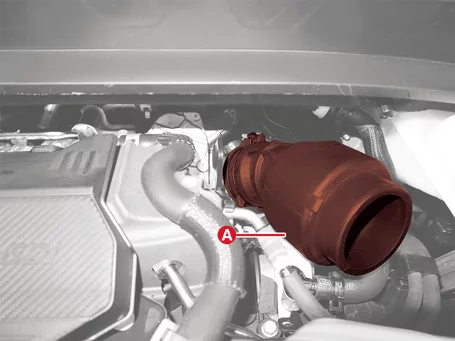
Remove the resonator (A) after releasing the clamp.
|
| 9.
|
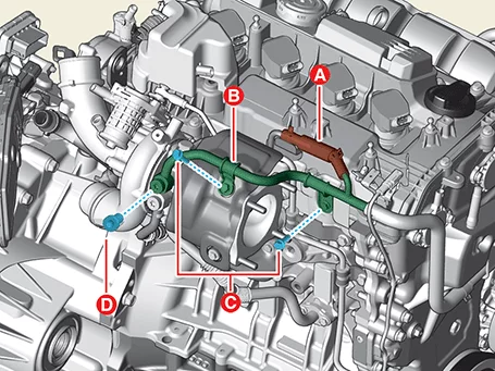
Remove the turbocharger water outlet pipe.
| (1)
|
Disconnect the turbocharger outlet hose (A) after releasing the clamp.
|
| (2)
|
Remove turbocharger water outlet pipe (B) after removing the bolts.
|
|
Tightening torque :
C : 9.8 - 11.8 N·m (1.0 - 1.2 kgf·m, 7.2 - 8.7 lb·ft)
D : 34.3 - 39.2 N·m (3.5 - 4.0 kgf·m, 25.3 - 28.9 lb·ft)
|
|
•
|
When installing turbocharger water inlet hose & pipe, check
that the eye bolt gasket
is installed.
|
|
•
|
Always use a new eye bolt gaskets.
|
|
|
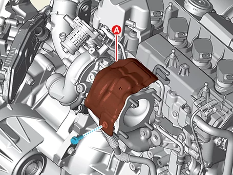
| 10.
|
Remove the turbocharger heat protector (A) after removing the bolt.
|
Tightening torque :
9.8 - 11.8 N·m (1.0 - 1.2 kgf·m, 7.2 - 8.7 lb·ft)
|
|
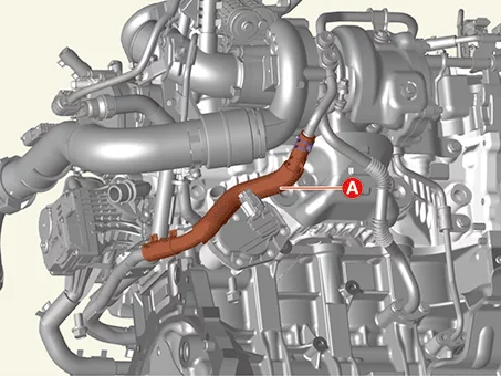
| 11.
|
Remove the turbocharger water inlet hose (A) after releasing the clamp.
|
| 12.
|
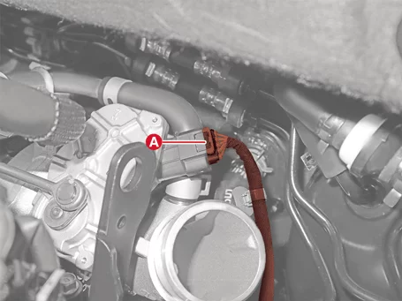
Disconnect the Electric Waste Gate Actuator (EWGA) connector (A).
|
| 13.
|
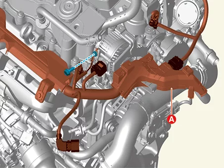
Disconnect the engine wiring (A) after removing the bolt.
|
Tightening torque :
9.8 - 11.8 N·m (1.0 - 1.2 kgf·m, 7.2 - 8.7 lb·ft)
|
|
| 14.
|
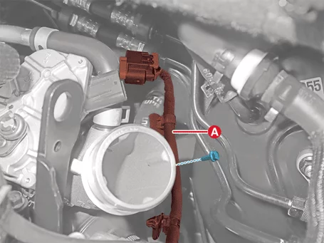
Remove the elbow pipe bracket and wiring (A) after removing the bolt.
|
Tightening torque :
9.8 - 11.8 N·m (1.0 - 1.2 kgf·m, 7.2 - 8.7 lb·ft)
|
|
| 15.
|
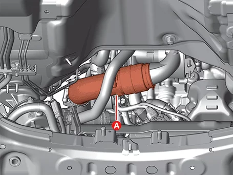
Disconnect the intercooler inlet hose (A) after releasing the quick connector.
|
| 16.
|
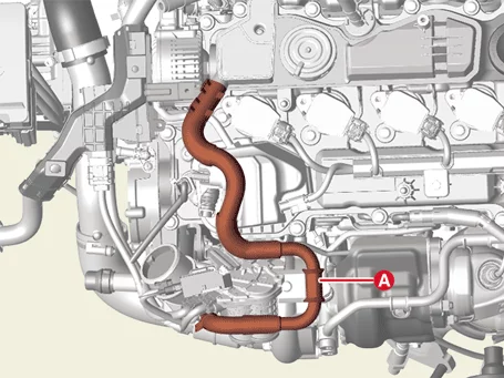
Disconnect the breather hose (A) after releasing the clamp.
|
| 17.
|
Remove the Front Subframe.
(Refor to Suspension System - "Front Subframe")
|
| 18.
|
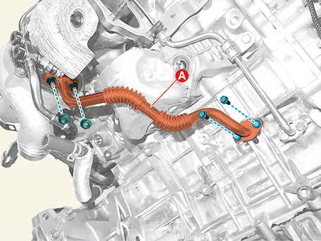
Remove the oil drain pipe (A) after removing the bolts and nuts.
|
Tightening torque :
9.8 - 11.8 N·m (1.0 - 1.2 kgf·m, 7.2 - 8.7 lb·ft)
|
|
| 19.
|
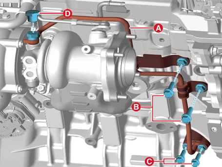
Remove the oil feed pipe (A) after removing the bolts.
|
Tightening torque
B : 18.6 - 23.5 N·m (1.9 - 2.4 kgf·m,
13.7 - 17.4 lb·ft)
C : 9.8 - 11.8 N·m (1.0 - 1.2 kgf·m,
7.2 - 8.7 lb·ft)
D : 16.7 - 21.6 N·m (1.7 - 2.2 kgf·m,
12.3 - 15.9 lb·ft)
|
|
•
|
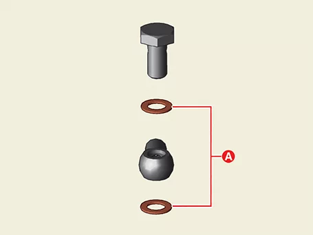
Do not reuse the copper washer (A).
|
|
•
|
When installing, make sure that a new copper washer (A) is
installed.
|
|
|
| 20.
|
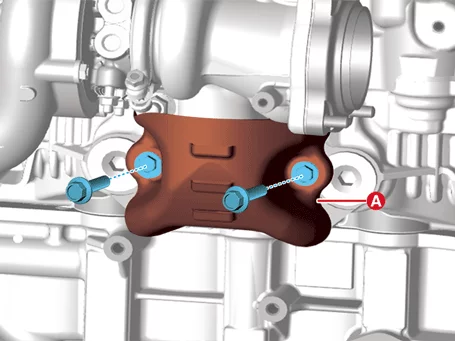
Remove the exhaust manifold heat protector (A) after removing the bolts.
|
Tightening torque :
9.8 - 11.8 N·m (1.0 - 1.2 kgf·m, 7.2 - 8.7 lb·ft)
|
|
| 21.
|
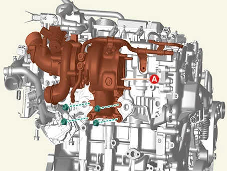
Remove the turbo manifold module (A) with gasket after removing the nuts.
|
Tightening torque :
49.0 - 53.9 N·m (5.0 - 5.5 kgf·m, 36.2 - 39.8 lb·ft)
|
|
Do not reuse the turbo manifold module gasket.
|
|
| 1.
|
Install in reverse order of removal.
|
•
|
Install the turbo manifold to the specified torque.
|
|
•
|
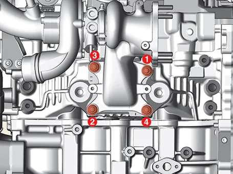
When install the turbo manifold module, attach the nut in the
sequence shown below and
tighten it completely with the torque prescribed.
|
|
|
Turbo Manifold Disassembly and Reassembly
| 1.
|
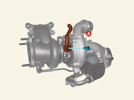
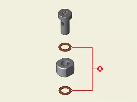
Remove the turbocharger water inlet pipe (A) after removing the bolt.
|
Tightening torque :
34.3 - 39.2 N·m (3.5 - 4.0 kgf·m, 25.3 - 28.9 lb·ft)
|
|
•
|
Do not reuse the copper washer (A).
|
|
•
|
When installing, make sure that a new copper washer (A) is
installed.
|
|
|
| 2.
|
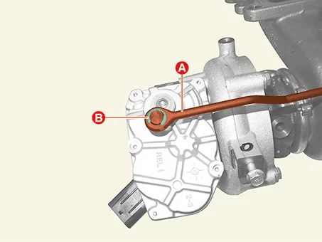
Separate the Electric Waste Gate Actuator (EWGA) rod (A) after removing the retaining ring.
|
| 3.
|
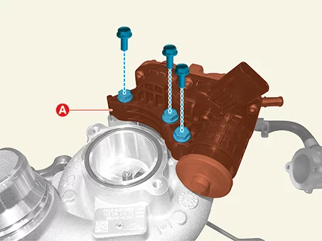
Remove the Electric Waste Gate Actuator (EWGA) (A) after removing the bolt.
|
Tightening torque :
9.8 - 11.8 N·m (1.0 - 1.2 kgf·m, 7.2 - 8.7 lb·ft)
|
|
| 1.
|
Reassembly in reverse order of disassembly.
|
Assemble the turbocharger to the specified torque.
|
|
Intercooler Components and Components Location
| Components and Components Location |
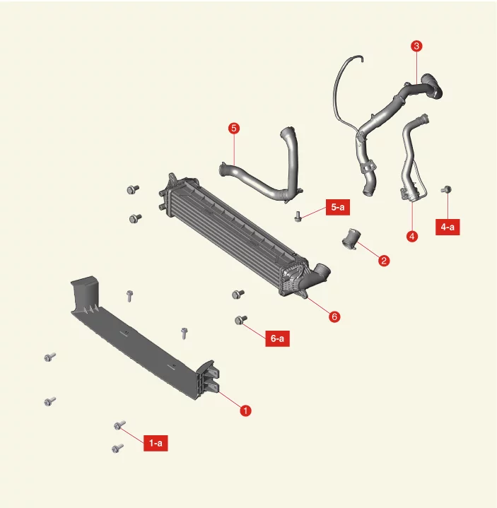
1. Intercooler Air Guide
1-a. 9.8 - 11.8
N·m (1.0 -
1.2 kgf·m, 7.2 - 8.7 lb·ft)
2. Intercooler Hose C
3. Intercooler Inlet Hose
4.
Recirculation Control
Valve (RCV) Hose
4-a. 7.8 - 11.8 N·m (0.8 - 1.2 kgf·m, 5.8 - 8.7 lb·ft)
|
5. Intercooler Outlet Hose
5-a. 21.6 - 25.5
N·m
(2.2 - 2.6 kgf·m, 15.9 - 18.8 lb·ft)
6. Intercooler
6-a. 9.8 - 11.8 N·m (1.0 - 1.2 kgf·m, 7.2
- 8.7
lb·ft)
|
Intercooler Removal and Installation
| 1.
|
Disconnect the battery negative ( - ) terminal.
|
| 2.
|
Remove the engine room under cover.
(Refer to Engine and Transaxle Assembly - "Engine Room Under
Cover")
|
| 3.
|
Remove the air cleaner assembly.
(Refer to Intake and Exhaust System - "Air Cleaner
Assembly")
|
| 4.
|
Remove the front bumper beam.
(Refer to Body - "Front Bumper Beam Assembly")
|
| 5.
|
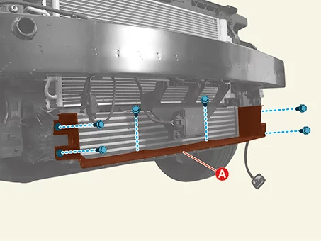
Remove the intercooler air guide (A) after removing the bolts.
|
Specified torque :
9.8 - 11.8 N·m (1.0 - 1.2 kgf·m, 7.2 - 8.7 lb·ft)
|
|
| 6.
|
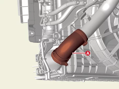
Remove the intercooler inlet hose C (A) after releasing the clamp.
|
| 7.
|
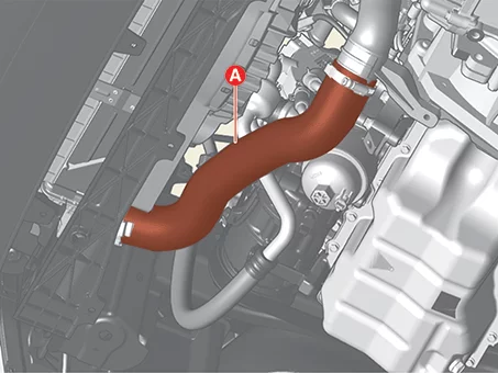
Disconnect the intercooler outlet hose (A) after releasing the clamp.
|
| 8.
|
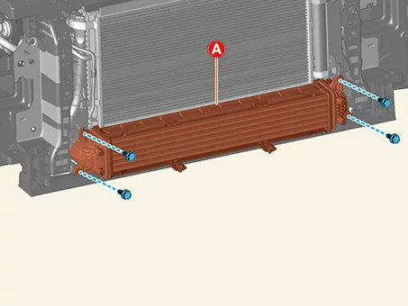
Remove the intercooler (A) after removing the bolts.
|
Specified torque :
9.8 - 11.8 N·m (1.0 - 1.2 kgf·m, 7.2 - 8.7 lb·ft)
|
|
| 1.
|
Install in reverse order of removal.
|
Install the intercooler to the specified torque.
|
|
Muffler Components and Components Location
| Components and Components Location |
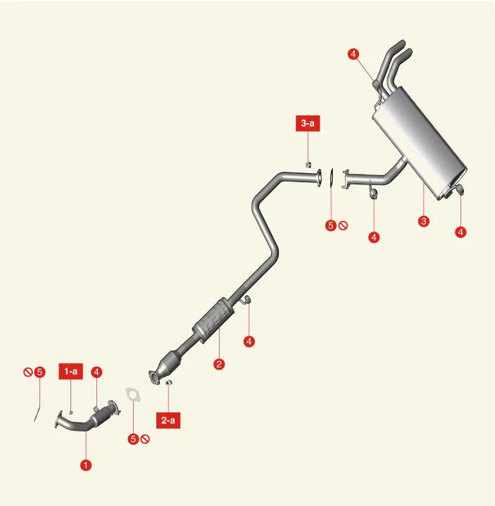
1. Front
Muffler
1-a. 39.2
- 58.8 N·m (4.0 - 6.0 kgf·m, 28.9 - 43.4 lb·ft)
2. Catalytic Converter and Center Muffler
Assembly
2-a.
39.2 - 58.8 N·m (4.0 - 6.0 kgf·m, 28.9 - 43.4 lb·ft)
3. Rear Muffler
3-a. 39.2 - 58.8 N·m (4.0
- 6.0
kgf·m, 28.9 - 43.4 lb·ft)
|
4. Hanger
5.
Gasket
|
Muffler Removal and Installation
|
•
|
This video was created using 3D graphics to help understand the vehicle
maintenance manual.
|
|
•
|
There may be some differences from actual vehicles.
|
|
•
|
The location and repair procedures of the parts may vary depending on vehicle
model, model year,
region, and specifications.
|
|
•
|
Check the KDS Guide for detailed information on how to use the KDS.
|
|
•
|
Check the manual for detailed maintenance procedures.
|
|
•
|
Unauthorized reproduction, distribution, or sharing of this video is
prohibited.
|
|
Center Muffler Replacement
(Click to play)
Video: Center Muffler Replacement
| 1.
|
Remove the rear Heated Oxygen Sensor (HO2S)
(Refer to Engine Control / Fuel System - "Heated Oxygen Sensor
(HO2S)")
|
| 2.
|
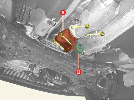
Remove the front muffler (A).
| (1)
|
Separate the rubber hanger (B).
|
| (2)
|
Remove the front muffler (A) after removing the nuts.
|
Tightening torque :
39.2 - 58.8 N·m (4.0 - 6.0 kgf·m, 28.9 - 43.4 lb·ft)
|
|
|
Catalytic Converter & Center Muffler Assembly
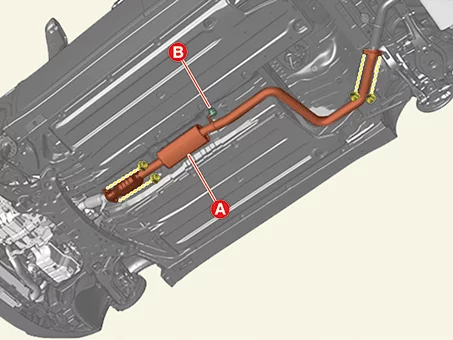
| 1.
|
Remove the catalytic converter & center muffler assembly.
| (1)
|
Remove the catalytic converter & center muffler hanger (B).
|
| (2)
|
Remove the catalytic converter & center muffler assembly (A) after removing
the nuts.
|
Tightening torque :
39.2 - 58.8 N·m (4.0 - 6.0 kgf·m, 28.9 - 43.4 lb·ft)
|
|
|
Catalytic Converter
Under warranty : Replace the center muffler assembly.
Out of warranty : It is available to replace the center muffler as the procedure below.
| 1.
|
Check the center muffler for deformation or damage to the part where the clamp is to be
mounted.If clamp
mounting is not possible, replace with a center muffler assembly.
|
| 2.
|
If clamps are available, measure and record the distance between the tail trim and rear bumper
(A).
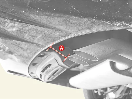
|
| 3.
|
Remove the catalytic converter & center muffler assembly.
| (1)
|
Remove the catalytic converter & center muffler hanger (B).
|
| (2)
|
Remove the catalytic converter & center muffler assembly (A) after removing
the nuts.
|
Tightening torque :
39.2 - 58.8 N·m (4.0 - 6.0 kgf·m, 28.9 - 43.4 lb·ft)
|
|
|
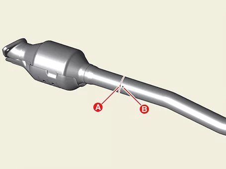
| 4.
|
Cut the clamp tightening point of the center muffler.
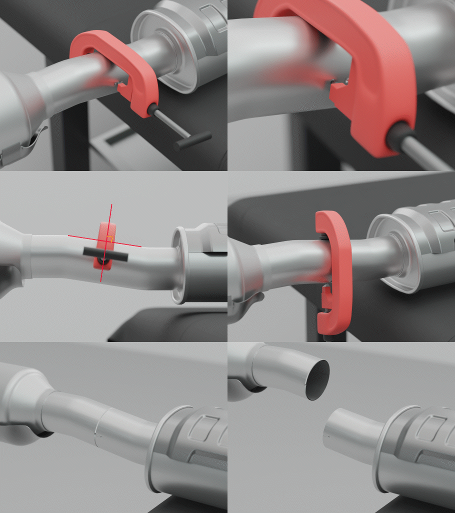
– Cut the front dent position of the muffler.
A : Front dent
B : Rear dent
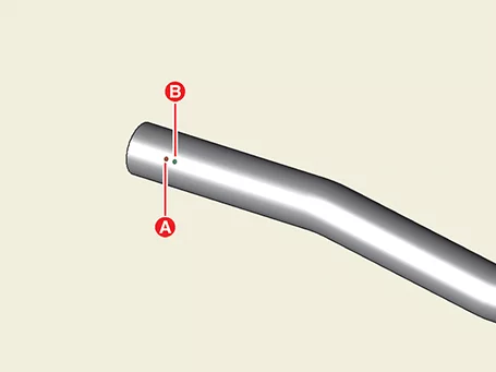
[New Muffler]
– Cut the rear dent of the replacement muffler.
A : Front dent
B : Rear dent
C : Center groove
D : Rear groove
|
•
|
After tightening the fixture, remove foreign objects, rust,
welding spatter and cutting
residue on the cutting surface to prevent leakage and welding of
the cut part of the pipe.
|
|
•
|
The pipe is cut vertically.
|
|
|
•
|
Use an easy-to-cut pipe cutter that is smooth and perpendicular
to the cut surface.
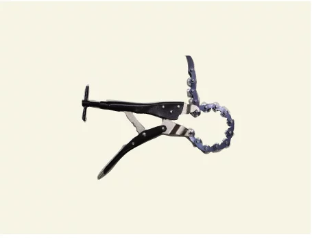
|
|
•
|
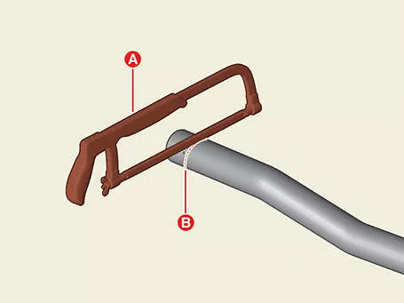
If a pipe cutter is not available, use a hacksaw as per the
procedure below.
1) Marking (A) is made around the pipe in the dent position to
cut the pipe vertically.
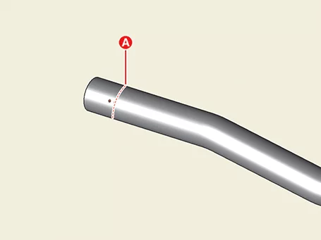
2) Cut the pipe along the marking line (B) using a hacksaw (A).
|
|
|
| 5.
|
Install the center muffler.
| (1)
|
Install the catalytic converter and attach the central muffler (A) and hanger
(B).
|
Tightening torque :
39.2 - 58.8 N·m (4.0 - 6.0 kgf·m, 28.9 - 43.4 lb·ft)
|
|
Replace with a new gasket upon installation
|
|
| (2)
|
Install the clamp (A) both cutting parts and tighten the clamp lightly, not
completely.
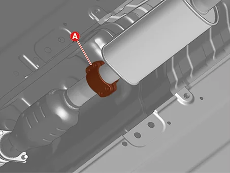
|
| (3)
|
Before removing the center muffler, check the distance between the tailpipe (or
tail trim) and
the rear bumper with a measurement record and realign if there is a problem.
|
If the position of the tail pipe is different from the initial
state, the bumper may be
damaged due to interference, noise, and heat between the tail
pipe and the rear bumper.
|
|
| (4)
|
Tighten the clamp nut several times evenly.
|
Tightening torque :
17.7 - 24.5 N·m (1.8 - 2.5 kgf·m, 13.0 - 18.1 lb·ft)
|
|
Do not reuse a fully tightened clamp it may have internal
deformation.
|
|
|
| 1.
|
Remove the rear muffler.
| (1)
|
Remove the rubber hanger (B).
|
| (2)
|
Remove the rear muffler (A) after removing the nuts.
|
Tightening torque :
39.2 - 58.8 N·m (4.0 - 6.0 kgf·m, 28.9 - 43.4 lb·ft)
|
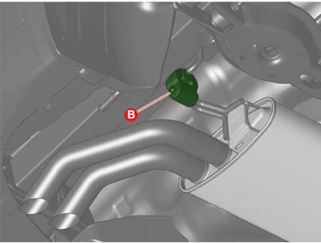
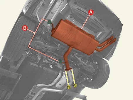
|
|
| 1.
|
Install in reverse order of removal.
|
Install to the specified torque.
|
|