Contents:
Engine Oil Replacement
| Oil And Filter Replacement |
|
•
|
Prolonged and repeated contact with mineral oil will result in the removal of
natural fats from
the skin, leading to dryness, irritation and dermatitis. In addition, used
engine oil contains
potentially harmful contaminants which may cause skin cancer.
|
|
•
|
Exercise caution in order to minimize the length and frequency of contact of
your skin to used
oil. Wear protective clothing and gloves. Wash your skin thoroughly with soap
and water, or use
water-less hand cleaner, to remove any used engine oil. Do not use gasoline,
thinners, or solvents.
|
|
•
|
In order to preserve the environment, used oil and used oil filter must be
disposed of only at
designated disposal sites.
|
|
|
Never use any additives to engine oil, as they can change the properties of engine oil which
can cause
serious engine failure.
|
| 1.
|
Drain the engine oil.
| (1)
|
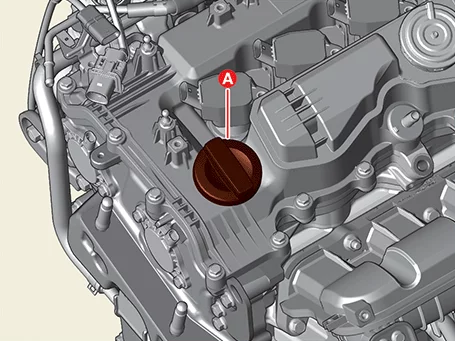
Open the oil filler cap (A).
|
| (2)
|
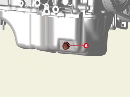
Remove the drain plug (A) and then drain the oil.
|
|
| 2.
|
Replace the oil filter.
| (1)
|
Remove the safety pin (A).
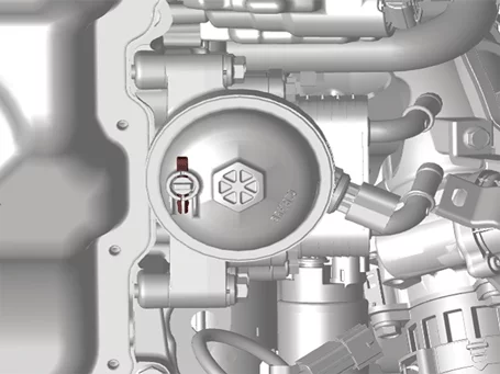
|
| (2)
|
Remove the free drain plug (A) by rotating it 90° and drain the engine oil from
the oil filter.
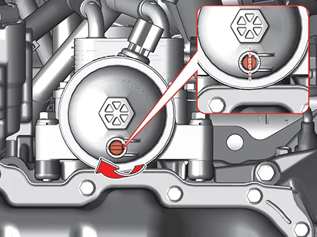
|
| (3)
|
Remove the oil filler cap (B) using a socket wrench (A).
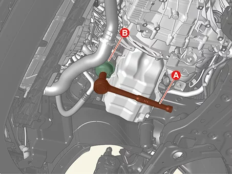
|
| (4)
|
Install the new O-ring (A) on the oil filter cap.
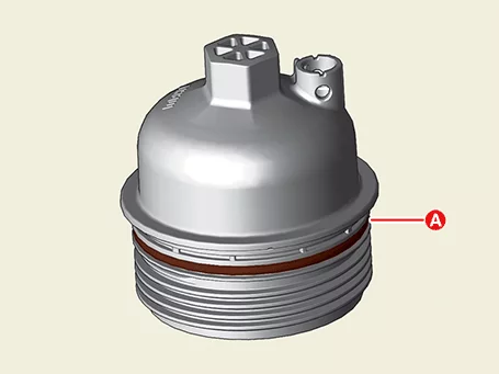
|
| (5)
|
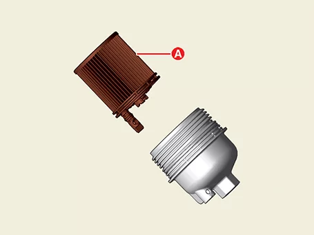
Install a new oil filter (A).
|
•
|
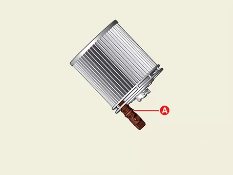
Must use the drain plug (A) which is installed
on a new oil filter.
|
|
•
|
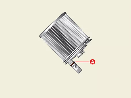
Apply engine oil on drain plug O-ring (A) when
the installation of oil filter.
|
|
|
| (6)
|
Rotate the free drain plug (A) 90° so that the drain pin is in the locked
position.
|
| (7)
|
Install the new safety pin (A).
|
Do not reuse the safety pin.
|
|
| (8)
|
Install the oil filter cap (B) using the socket wrench (A).
|
Tightening torque :
34.3 N·m (3.5 kgf·m, 25.3 lb·ft)
|
|
•
|
When installing the oil filter cap, check that
the new O-ring is seated in place
of the cap.
|
|
•
|
When installing the oil filter cap, and then
apply engine oil to new O-ring.
|
|
|
|
| 3.
|
Fill the engine with oil.
| (1)
|
Install the oil drain plug (A) with the new gasket.
|
Tightening torque :
34.3 - 44.1 N·m (3.5 - 4.5 kgf·m, 25.3 - 32.5 lb·ft)
|
|
| (2)
|
Fill new engine oil through the oil filler hole.
Remove the oil level gauge before adding oil.
|
Oil capacity
Total :
5.0 ℓ (1.32 U.S.gal., 5.28 U.S.qt., 4.40 lmp.qt.)
Oil pan :
4.4 ℓ (1.16 U.S.gal., 4.65 U.S.qt., 3.87 lmp.qt.)
Drain and refill (include oil
filter) :
4.8 ℓ (1.27 U.S.gal., 5.07 U.S.qt., 4.22 lmp.qt.)
|
|
Inject 1/2 of the total capacity first and then the remaining
1/2 after approximately 1
minute.
|
|
| (3)
|
Install the oil filler cap (A).
|
| (4)
|
Install the oil level gauge.
|
|
| 4.
|
Start engine and check for leaks.
|
| 5.
|
Recheck the engine oil level.
|
•
|
Before rechecking the engine oil level, sufficiently warm up
the engine.
|
|
•
|
If engine is not sufficiently warmed up, engine oil level could
be checked below the
specified value.
|
|
|
Engine Oil Inspection
| 1.
|
Check the condition of the engine oil.
Check for oil discoloration, moisture inflow, and viscosity drop,If the engine quality is
noticeably
poor, change the oil.
|
| 2.
|
After engine warm up stop the engine wait 15 minutes then check the oil level. Oil level should
be
between the "L" and "F" marks on the dipstick.
If the engine oil level is lower than "L", check for leaks and add engine oil to "F".
|
Be careful not to over the "F" marks.
|
|
Engine Oil Grade
For North America :
- API SN PLUS/SP or ILSAC GF-6 / SAE 0W-20
Allowed oil SAE viscosity : Refer to recommended SAE viscosity number
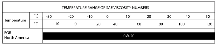
For best performance and maximum protection in all operating conditions, be sure to select the
following
lubricants.
| 1) |
The requirements of the API or ILSAC classification must be satisfied.
|
| 2) |
Do not use lubricants that do not have an SAE class number and API or ILSAC
class classification
marked on the container.
|
| 3) |
Never use any additives to engine oil, as they can change the properties of
engine oil which can
cause serious engine failure.
|
|
Oil Filter & Oil Cooler Components and Components Location
| Components and Components Location |
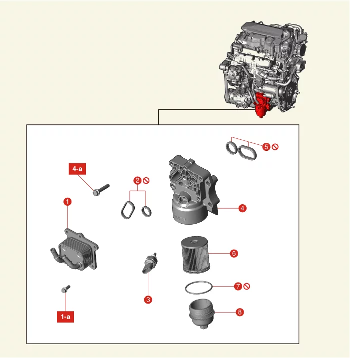
1. Oil Cooler
1-a.
9.8 -
11.8 N·m (1.0 - 1.2 kgf·m, 7.2 - 8.7 lb·ft)
2. Oil Cooler Form Seal
3. Oil Pressure &
Temperature
Sensor (OPTS)
4. Oil Filter Body
4-a. 22.6 - 27.5 N·m (2.3 - 2.8 kgf·m, 16.6 - 20.3 lb·ft)
|
5. Oil Filter &
Oil Cooler
Seal
6. Oil Filter
7. Oil Filter Ring
8. Oil Cap
|
Oil Filter & Oil Cooler Removal and Installation
| 1.
|
Disconnect the battery negative ( - ) terminal.
|
| 2.
|
Remove the engine room under cover.
(Refer to Engine and Transaxle Assembly - "Engine Room Under
Cover")
|
| 3.
|
Drain the coolant.
(Refer to Cooling System - "Coolant")
|
| 4.
|
Drain engine oil.
(Refer to Lubrication System - "Engine Oil")
|
| 5.
|
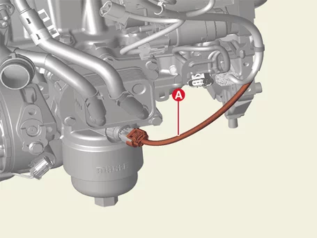
Disconnect the Oil Pressure & Temperature Sensor (OPTS) connector (A).
|
| 6.
|
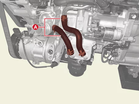
Disconnect the oil cooler hose (A) after releasing the clamps.
|
Do not apply excessive force when disconnecting and reconnecting the oil cooler
coolant hose.
Otherwise, coolant may leak due to the deformation of cooler nipple.
|
|
| 7.
|
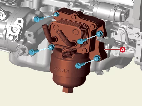
Remove the oil filter & oil cooler (A) after removing the bolts.
|
Tightening torque :
22.6 - 27.5 N·m (2.3 - 2.8 kgf·m, 16.6 - 20.3 lb·ft)
|
|
| 8.
|
Remove the oil filter & oil cooler form seal (A).
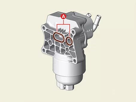
|
When installing, make sure that there is 2 form seal on the mounting surface of
the oil filter
and oil cooler.
|
|
| 9.
|
Remove the oil cooler (A) after removing the bolts from the oil filter
|
Tightening torque :
9.8 - 11.8 N·m (1.0 - 1.2 kgf·m, 7.2 - 8.7 lb·ft)
|
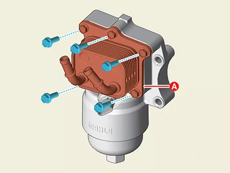
|
| 10.
|
Remove the oil cooler seal (A).
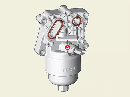
|
when installing, make sure that there is 2 form seal on the mounting surface of
the oil cooler.
|
|
| 1.
|
Install in reverse order of removal.
|
Install the oil filter and oil cooler to the specified torque.
|
|
| 2.
|
Fill the engine with oil.
(Refer to Lubrication System - "Engine Oil")
|
| 3.
|
Fill with coolant.
(Refer to Cooling System - "Coolant")
|
Be sure to add coolant according to the ITM coolant refill method.
|
|
Oil Pan Components and Components Location
| Components and Components Location |
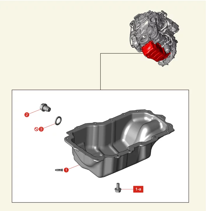
1. Oil Pan
1-a.
9.8 - 11.8
N·m (1.0 - 1.2 kgf·m, 7.2 - 8.7 lb·ft)
2. Oil Drain Plug
3. Oil Drain Plug Gasket
|
Oil Pan Removal
| 1.
|
Remove the engine room under cover.
(Refer to Engine and Transaxle Assembly - "Engine Room Under
Cover")
|
| 2.
|
Drain engine oil.
(Refer to Lubrication System - "Engine Oil")
|
| 3.
|
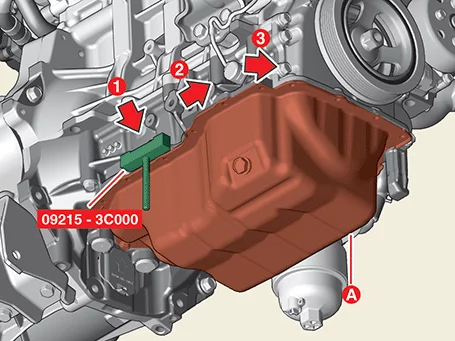
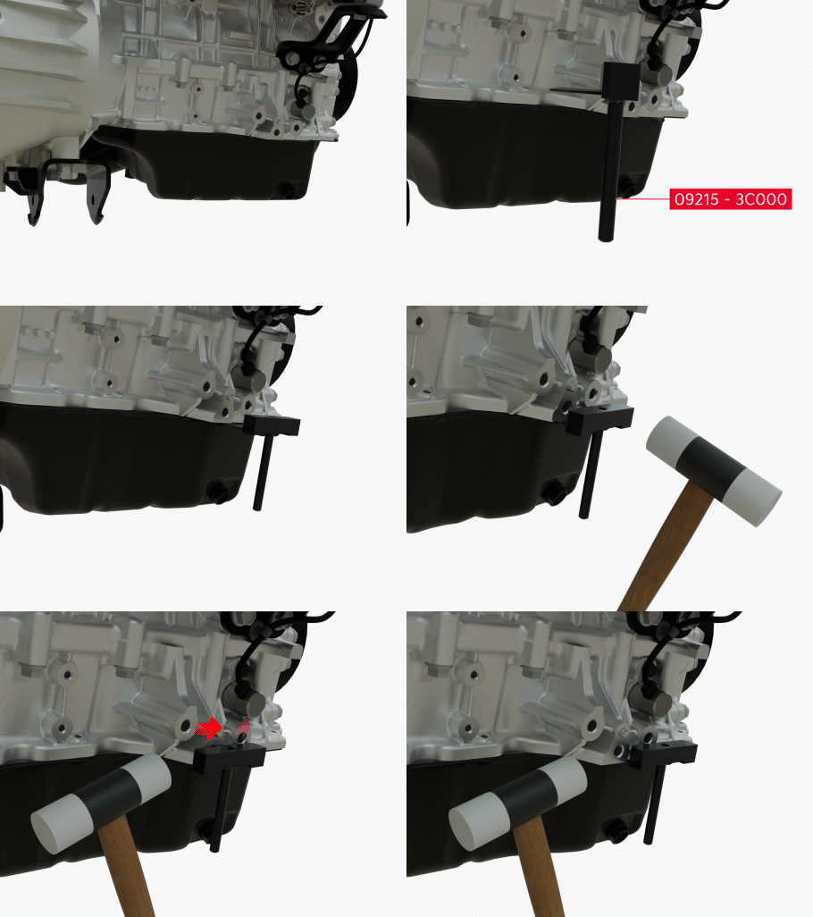
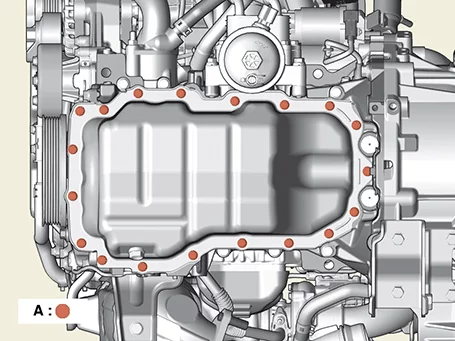
Remove the oil pan (A) after removing the bolts.
|
When removing the oil pan, be careful not to damage the mating surface between
the lower
crankcase and oil pan using the SST (09215 - 3C000).
|
|
Oil Pan Installation
| 1.
|
Install the oil pan.
| (1)
|
Before assembling the oil pan, remove the hardening sealant, foreign material,
oil, dust,
moisture remaining on the sealing surface and on the mating part.
|
| (2)
|
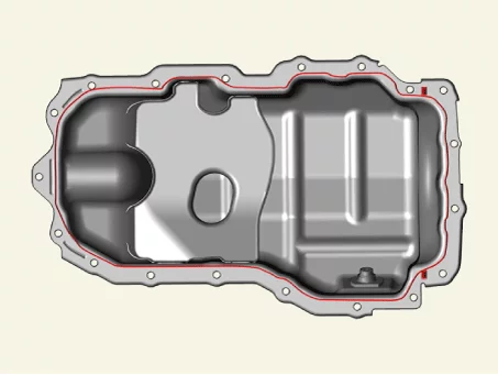
Assemble the oil pan within 5 minutes after applying sealant.
|
Bead width : 2.5 - 3.5
mm (0.0984 - 0.1378 in.)
Sealant specifications :
THREEBOND 1217H / LOCTITE
5900H or equivalent
|
|
•
|
sealant must not be protruded into the inside
of oil pan.
|
|
•
|
The sealant application must be inside the bolt
groove.
|
|
•
|
When applying sealant gasket on the lower
crankcase, the sealant application line
should be same with that of the oil pan.
|
|
|
|
| 2.
|
Assemble the oil pan (A) and then uniformly tighten the oil pan bolts in several passes.
|
Tightening torque :
9.8 - 11.8 N·m (1.0 - 1.2 kgf·m, 7.2 - 8.7 lb·ft)
|
|
After assembling the oil pan, fill engine oil after at least 30 minutes have
elapsed.
|
|
| 3.
|
Install in reverse order of removal.
|
| 4.
|
Fill the engine with oil.
(Refer to Lubrication System - "Engine Oil")
|
| 5.
|
Install the engine room under cover.
(Refer to Engine and Transaxle Assembly - "Engine Room Under
Cover")
|
Oil Level Gauge Removal and Installation
| 1.
|
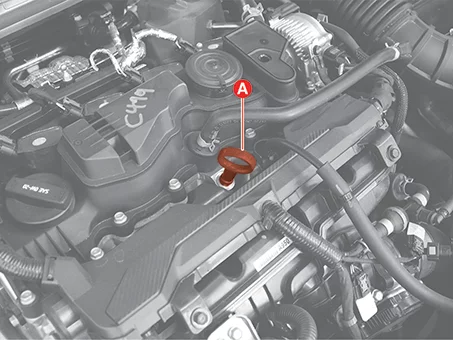
Remove the oil level gauge (A).
|
| 1.
|
Install in reverse order of removal.
|
Oil Pump Components and Components Location
| Components and Components Location |
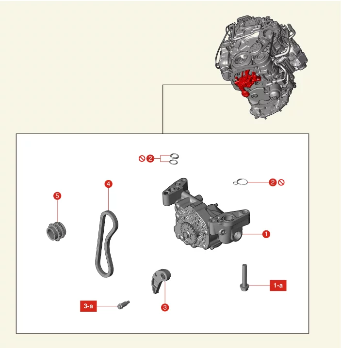
1. Oil Pump
1-a.
18.6 -
23.5 N·m (1.9 - 2.4 kgf·m, 13.7 - 17.4 lb·ft)
2. Oil Pump O-Ring
|
3. Oil Pump Chain Tensioner
3-a. 9.8 -
11.8 N·m
(1.0 - 1.2 kgf·m, 7.2 - 8.7 lb·ft)
4. Oil Pump Chain
5. Crankshaft Sprocket
|
Oil Pump Removal and Installation
Oil pump chain
| 1.
|
Remove the timing chain.
(Refer to Timing System - "Timing Chain Cover")
|
| 2.
|
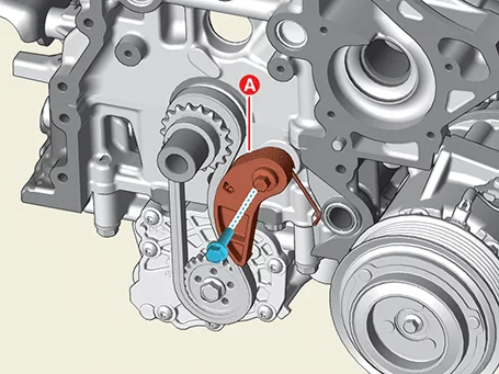
Remove the oil pump chain tensioner (A) after removing the bolt.
|
Tightening torque :
9.8 - 11.8 N·m (1.0 - 1.2 kgf·m, 7.2 - 8.7 lb·ft)
|
|
| 3.
|
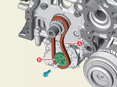
Remove the oil pump sprocket (B) and oil pump chain (A) after removing the bolt.
|
Tightening torque :
21.6 - 22.6 N·m (2.2 - 2.3 kgf·m, 15.9 - 16.6 lb·ft)
|
|
Oil Pump
| 1.
|
Remove the engine room under cover.
(Refer to Engine and Transaxle Assembly – "Engine Room Under
Cover")
|
| 2.
|
Drain the engine oil.
(Refer to Lubrication System - "Engine Oil")
|
| 3.
|
Remove the oil pan.
(Refer to Lubrication - "Oil Pan")
|
| 4.
|
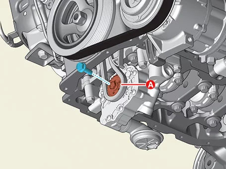
Remove the oil pump sprocket (A) after removing the bolt.
|
Tightening torque :
21.6 - 22.6 N·m (2.2 - 2.3 kgf·m, 15.9 - 16.6 lb·ft)
|
|
| 5.
|
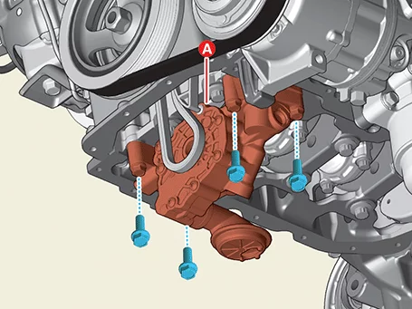
Remove the oil pump (A), after removing the bolts.
|
Tightening torque :
18.6 - 23.5 N·m (1.9 - 2.4 kgf·m, 13.7 - 17.4 lb·ft)
|
|
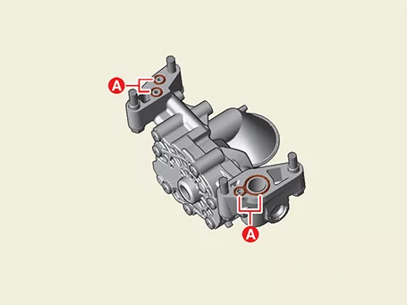
Do not reuse the oil pump O-ring.
|
|
| 1.
|
Install in reverse order of removal.
|
Install the oil pump chain to the specified torque.
|
|
| 2.
|
Fill the engine with oil.
(Refer to Lubrication System - "Engine Oil")
|
Oil Level Sensor Removal and Installation
| 1.
|
Disconnect the battery negative ( - ) terminal.
|
| 2.
|
Drain the engine oil.
(Refer to Lubrication System - “Engine Oil”)
|
| 3.
|
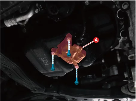
Remove the oil level sensor cover (A) after removing the nuts.
|
Tightening torque :
9.8 - 11.8 N·m (1.0 - 1.2 kgf·m, 7.2 - 8.7 lb·ft)
|
|
| 4.
|
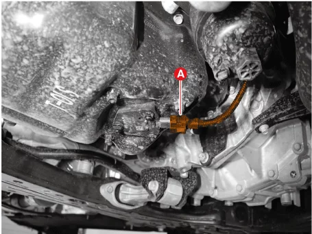
Disconnect the oil level sensor connector.
|
| 5.
|
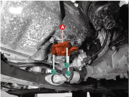
Remove the oil level sensor (A) after removing the nuts.
|
Tightening torque :
8.8 - 9.8 N·m (0.9 - 1.0 kgf·m, 6.5 - 7.2 lb·ft)
|
|
| 1.
|
Install in the reverse order of removal
|
| 2.
|
Fill engine oil.
(Refer to Lubrication System - "Engine Oil")
|
Other information:
Kia K4 (CL4) 2025-2026 Service Manual: Fuse/relay panel description
Located on the interior side of the fuse and relay panel covers, you will find a detailed label identifying the function, name, and amperage capacity of each fuse and relay for your Kia K4. This information is essential for troubleshooting electrical systems efficiently.
TIP
While the fuse panel descriptions provided in this manual are accurate as of the printing date, please be aware that minor variations in configuration may occur depending on the specific trim level, production date, and optional equipment fitted to your Kia K4.
Kia K4 (CL4) 2025-2026 Service Manual: Tightening Torque
Tightening Torque
Cooling System
Cooling Fan
Item
N·m
kgf·m
lb·ft
lb·in
Degassing hose clip bolt
3.



 .
 to
 around more than 2/3 edge of the oil pan, remove the oil pan
from the lower crankcase.