Contents:
Components and Components Location
| Components and Components Location |
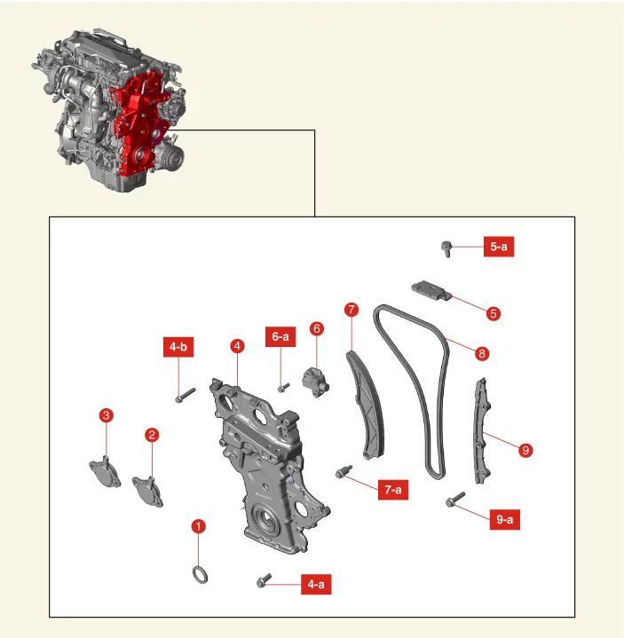
1. Front Oil
Seal
2. Intake
Variable Force Solenoid (VFS) Valve
2-a. 9.8 - 11.8 N·m (1.0 - 1.2 kgf·m, 7.2 - 8.7 lb·ft)
3.
Exhaust
variable force solenoid (VFS) valve
3-a. 9.8 - 11.8 N·m (1.0 - 1.2 kgf·m, 7.2 - 8.7 lb·ft)
4.
Timing
Chain Cover
4-a. 18.6 - 23.5 N·m (1.9 - 2.4 kgf·m, 13.7 - 17.4 lb·ft)
4-b. 39.2 - 44.1 N·m
(4.0 - 4.5
kgf·m, 28.9 - 32.5 lb·ft)
5. Timing Chain Cam to Cam Guide
5-a. 9.8 - 11.8 N·m (1.0 - 1.2
kgf·m, 7.2 -
8.7 lb·ft)
6. Timing Chain Tensioner
6-a. 9.8 - 11.8 N·m (1.0 - 1.2 kgf·m, 7.2 - 8.7
lb·ft)
|
7. Timing Chain
Tensioner Arm
7-a. 9.8 - 11.8 N·m (1.0 - 1.2 kgf·m, 7.2 - 8.7 lb·ft)
8. Timing Chain
9. Timing Chain
Guide
9-a.
9.8 - 11.8 N·m (1.0 - 1.2 kgf·m, 7.2 - 8.7 lb·ft)
|
Front Oil Seal Replacement
Tool Name / Number
|
Illustration
|
Description
|
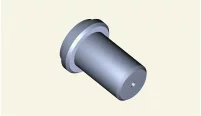
Crankshaft front oil seal installer
0K231 - 2C200
|
|
front oil seal installer
|
| 1.
|
Remove the crankshaft damper pulley.
(Refer to Drive Belt System - "Crankshaft Damper
Pulley")
|
| 2.
|
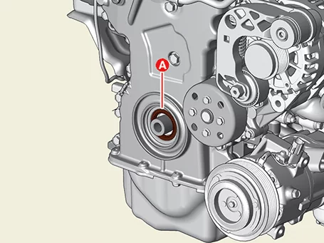
Remove the front oil seal (A).
|
| 3.
|
Install the new front oil seal.
| (1)
|
Apply engine oil to the edge of the new oil seal.
|
Remove any debris from the oil seal lip.
|
|
| (2)
|
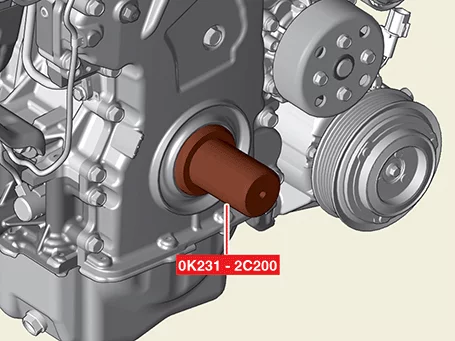
Using a special tool (0K231 - 2C200) and a rubber mallet, tap the new front oil
seal lightly and
install it.
|
|
Do not reuse front oil seal.
|
|
| 4.
|
Install in reverse order of removal.
|
Timing Chain Cover Removal
It is not necessary to remove the engine and transaxle assembly for this operation.
|
In case of removing the high pressure fuel pump, high pressure fuel pipe, delivery pipe, and
injector,
there may be injury caused by leakage of the high pressure fuel. So don’t do any repair work
right after
engine stops.
|
|
•
|
Use fender covers to avoid damaging painted surfaces.
|
|
•
|
Be careful not to damage the connector when disconnecting.
|
|
|
Mark all wiring and hoses to prevent incorrect connections.
|
| 1.
|
Release the residual pressure in fuel line.
(Refer to Fuel Delivery System - "Release Residual Pressure in
Fuel
Line")
|
| 2.
|
Disconnect the battery negative ( - ) terminal.
|
| 3.
|
Remove the engine cover.
(Refer to Engine and Transaxle Assembly - "Engine
Cover")
|
| 4.
|
Remove the engine room under cover.
(Refer to Engine and Transaxle Assembly - "Engine Room Under
Cover")
|
| 5.
|
Drain the coolant.
(Refer to Cooling System - "Coolant")
|
| 6.
|
Drain engine oil.
(Refer to Lubrication System - "Engine Oil")
|
| 7.
|
Remove the air cleaner assembly.
(Refer to Intake and Exhaust System - "Air Cleaner")
|
| 8.
|
Remove the drive belt.
(Refer to Drive Belt System - "Drive Belt")
|
| 9.
|
Remove the drive belt tensioner.
(Refer to Drive Belt System - "Drive Belt Tensioner")
|
| 10.
|
Remove the crankshaft damper pulley.
(Refer to Drive Belt System - "Crankshaft Damper
Pulley")
|
| 11.
|
Remove the water pump.
(Refer to Cooling System - "Water Pump")
|
| 12.
|
Remove the cylinder head cover.
(Refer to Cylinder Head Assembly - "Cylinder Head
Cover")
|
| 13.
|
Remove the oil pan.
(Refer to Lubrication - "Oil Pan")
|
| 14.
|
Support the jack at the bottom of the lower crankcase.
|
Put a rubber pad between the lower crankcase and the jack to prevent damage to
the lower
crankcase.
|
|
| 15.
|
Remove the engine mounting bracket.
(Refer to Engine And Transaxle Assembly - "Engine
Mounting")
|
| 16.
|
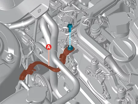
Separate the engine ground cable (A) after removing the bolt.
|
Tightening torque :
10.8 - 13.7 N·m (1.1 - 1.4 kgf·m, 8.0 - 10.1 lb·ft)
|
|
| 17.
|
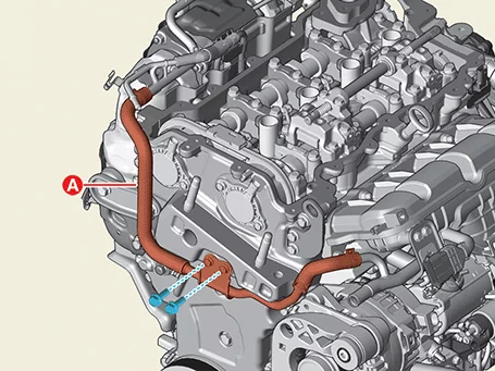
Release the clamp, and then remove the turbo charger cooling hose and pipe (A) after removing
the bolt.
|
Tightening torque :
9.8 - 11.8 N·m (1.0 - 1.2 kgf·m, 7.2 - 8.7 lb·ft)
|
|
| 18.
|
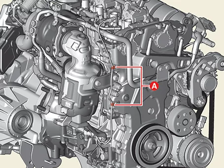
Separate the wiring fixing clip (A).
|
| 19.
|
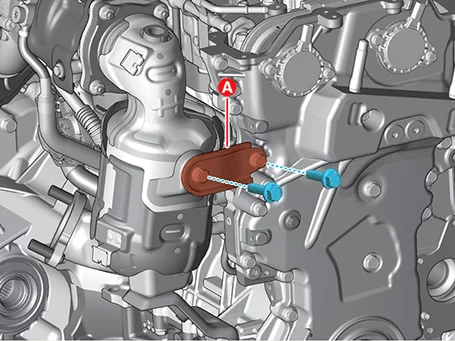
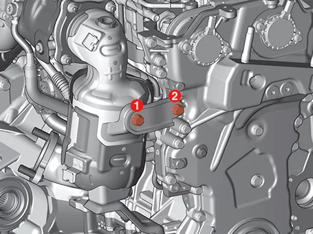
Warm-up Catalytic Converter (WCC) upper bracket, after removing the bolt.
|
Tightening torque :
39.2 - 44.1 N·m (4.0 - 4.5 kgf·m, 28.9 - 32.5 lb·ft)
|
|
Install the Warm-up Catalytic Converter (WCC) upper bracket and tighten the
bolts.
|
|
| 20.
|
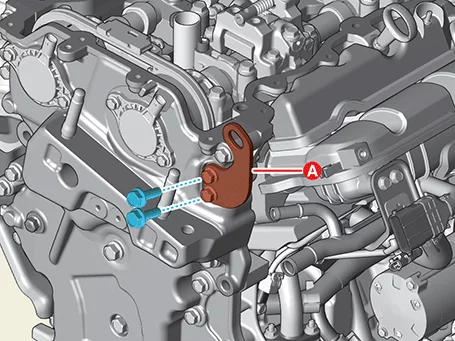
Remove the front engine hanger (A), after removing the bolt.
|
Tightening torque :
18.6 - 23.5 N·m (1.9 - 2.4 kgf·m, 13.7 - 17.4 lb·ft)
|
|
| 21.
|
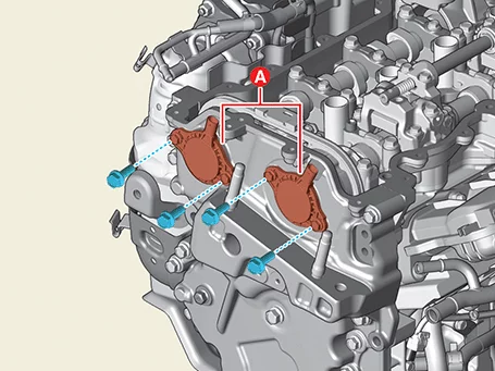
Remove the Variable Force Solenoid (VFS) (A) after removing the bolts.
|
When removing timing chain cover, remove the Variable Force Solenoid (VFS)
first.
|
|
| 22.
|
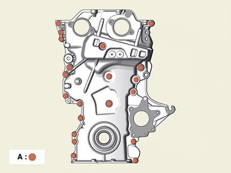
Remove the timing chain cover bolt (A).
|
| 23.
|
Remove the timing chain cover (A).
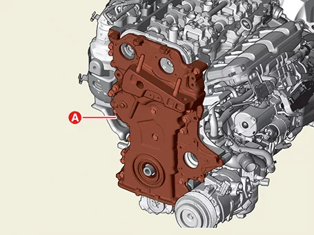
|
When removing the timing chain cover, be careful not to damage the contact
surfaces of the
cylinder block, cylinder head and lower crankcase.
|
|
Timing Chain Cover Installation
| 1.
|
Install the timing chain cover O-ring (A).
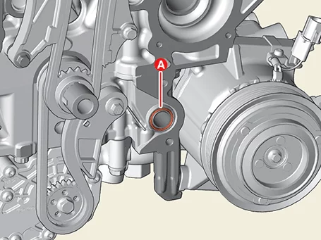
|
Do not reuse timing chain cover O-rings.
|
|
| 2.
|
Install the timing chain cover.
| (1)
|
Before assembling the timing chain cover, remove the cured sealant from the
surface on which the
chain cover will be mounted.
|
| (2)
|
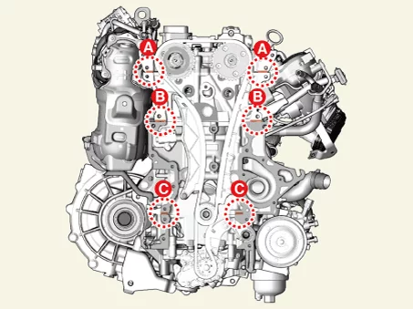
Apply the sealant to the interface (A) between the cam carrier and the cylinder
head, the
interface (B) between the cylinder head and the cylinder block, and the
interface (C) between the
cylinder block and the lower crankcase.
|
Width: 3.0 - 5.0 mm
(0.11811 - 0.19685 in.)
Sealant specifications :
THREEBOND 1217H / LOCTITE
5900H or equivalent
|
|
| (3)
|
Install within 5 minutes after applying sealant to the mounting surface of the
timing chain
cover.
|
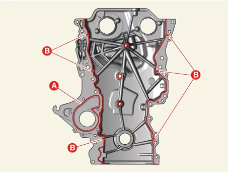
Bead width
Whole section : 2.5 -
3.5 mm (0.0984252 - 0.137795
in.)
A section : 1.5 - 2.5 mm
(0.0590551 - 0.0984252)
B section : 3.5 - 4.5 mm
(0.137795 - 0.177165 in.)
Sealant specifications
Whole section :
THREEBOND 1217H / LOCTITE 5900H or
equivalent
A section : THREEBOND
1217H / LOCTITE 5900H or
equivalent
|
|
| (4)
|
Install the timing chain cover (A) using the dowel pin of the cylinder block
and the hole of the
timing chain cover as a reference.
|
| (5)
|
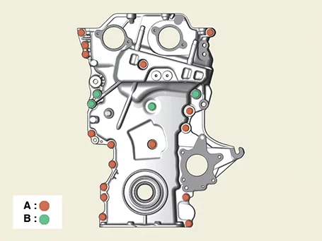
Tighten the timing chain cover bolts (A) and (B).
|
Tightening torque
A : 18.6 - 23.5 N·m (1.9 - 2.4 kgf·m, 13.7 - 17.4 lb·ft)
B : 39.2 - 44.1 N·m
(4.0 - 4.5 kgf·m, 28.9 - 32.5
lb·ft)
|
|
| (6)
|
Do not start the engine or apply pressure to the cover 30 minutes before
assembling the timing
chain cover.
|
|
| 3.
|
front oil seal exchange if necessary.
(Refer to Timing System - "Front Oil Seal")
|
| 4.
|
Install the variable force solenoid (VFS) (A) and then tighten the bolts.
|
Tightening torque :
9.8 - 11.8 N·m (1.0 - 1.2 kgf·m, 7.2 - 8.7 lb·ft)
|
|
•
|
If Variable Force Solenoid (VFS) valve is dropped, do not reuse
it.
|
|
•
|
When installing Variable Force Solenoid (VFS), observe the
precautions below.
|
| 1) |
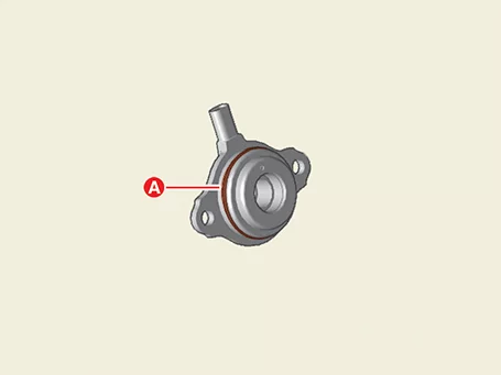
After replacing the Variable Force Solenoid (VFS) O-ring (A)
with a new one, apply engine
oil to the new O-ring (A).
|
| 2) |
After attaching Variable Force Solenoid (VFS) to the end of the
timing chain cover
mounting surface, temporarily fasten the bolt.
|
| 3) |
Install the Variable Force Solenoid (VFS) to the specified
torque.
|
|
|
| 5.
|
Install in reverse order of removal.
|
Install the timing chain cover to the specified torque.
|
|
| 6.
|
Fill the engine with oil.
(Refer to Lubrication System - "Engine Oil")
|
| 7.
|
Fill with coolant.
(Refer to Cooling System - "Coolant")
|
Be sure to add coolant according to the ITM coolant refill method.
|
|
| 8.
|
Start engine and check for any leaks.
|
Timing Chain Removal
| 1.
|
Release the residual pressure in fuel line.
(Refer to Fuel Delivery System - "Release Residual Pressure in
Fuel
Line")
|
| 2.
|
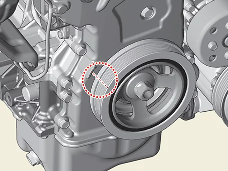
Turn the crankshaft damper pulley clockwise to bring the piston of cylinder 1 to compression
top dead
center so that the timing mark on the timing chain cover matches the groove on the damper
pulley.
|
| 3.
|
Remove the timing chain cover.
(Refer to Timing System - "Timing Chain Cover")
|
| 4.
|
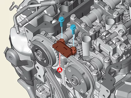
Remove the timing chain cam to cam guide (A) after removing the bolts.
|
| 5.
|
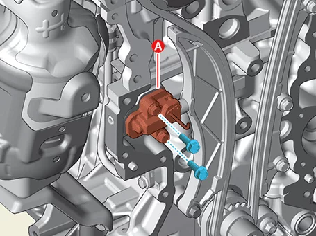
Remove the timing chain tensioner (A) after removing the bolt.
|
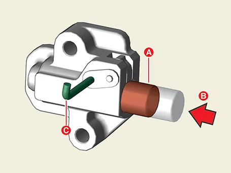
After compressing the timing chain tensioner piston (A) in the direction (B),
install the fixing
pin (C).
|
|
| 6.
|
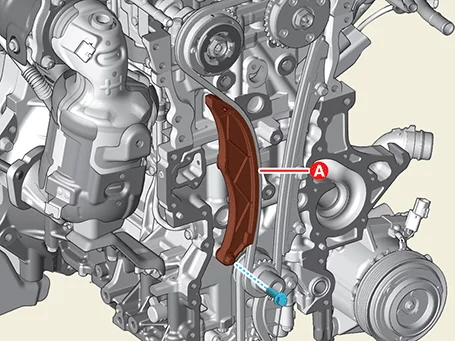
Remove the timing chain tensioner arm (A) after removing the bolt.
|
| 7.
|
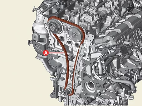
Remove the timing chain (A).
|
| 8.
|
Remove the timing chain guide (A) after removing the bolt.
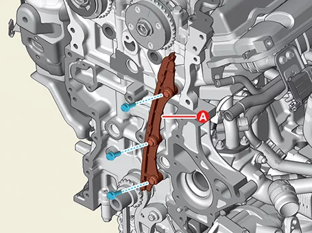
|
| 9.
|
Remove the oil pump chain.
(Refer to Lubrication System - "Oil Pump")
|
| 10.
|
Remove the crankshaft sprocket (A).
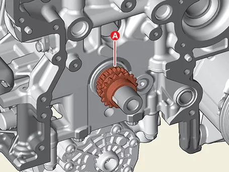
|
Timing Chain Installation
| 1.
|
Install the crankshaft sprocket (A).
|
| 2.
|
Install the oil pump chain.
(Refer to Lubrication System - "Oil Pump")
|
| 3.
|
Make sure the mounting surfaces of the crankshaft key and the lower crankcase are in a straight
line. At
this time, the piston of cylinder 1 is positioned at compression top dead center.
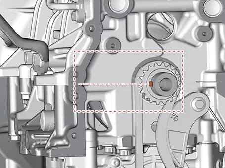
|
| 4.
|
Rotate so that the TDC marks on the intake CVVT sprocket and exhaust CVVT sprocket are aligned
with the
top surface of the cylinder head so that cylinder 1 is at compression top dead center.
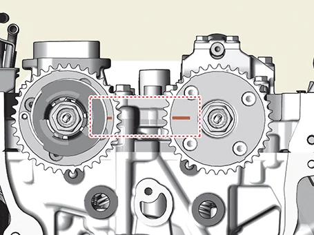
|
| 5.
|
Install the timing chain guide, and then tighten the bolt.
|
Tightening torque :
9.8 - 11.8 N·m (1.0 - 1.2 kgf·m, 7.2 - 8.7 lb·ft)
|
|
| 6.
|
Install the timing chain (A).
Crankshaft sprocket → timing chain guide → Intake CVVT sprocket → exhaust CVVT sprocket
|
When installing the timing chain, match the timing marks on each sprocket with
the timing marks
on the timing chain (A).
[Intake CVVT]
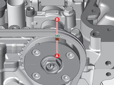
[Exhaust CVVT]
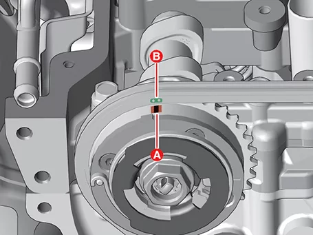
[Crankshaft]
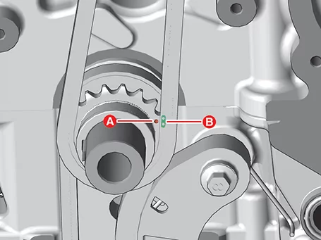
|
|
| 7.
|
Install the timing chain tensioner arm, and then tighten the bolt.
|
Tightening torque :
9.8 - 11.8 N·m (1.0 - 1.2 kgf·m, 7.2 - 8.7 lb·ft)
|
|
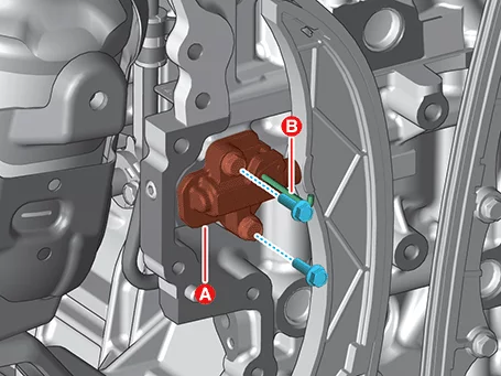
| 8.
|
Install the timing chain tensioner (A) and remove the retaining pin (B).
|
Tightening torque :
9.8 - 11.8 N·m (1.0 - 1.2 kgf·m, 7.2 - 8.7 lb·ft)
|
|
| 9.
|
Install the timing chain cam to cam guide, and then tighten the bolts.
|
Tightening torque :
9.8 - 11.8 N·m (1.0 - 1.2 kgf·m, 7.2 - 8.7 lb·ft)
|
|
| 10.
|
Turn the crankshaft clockwise 2 turns and check that the TDC marks on the front of the intake
and exhaust
CVVT sprockets are facing each other.
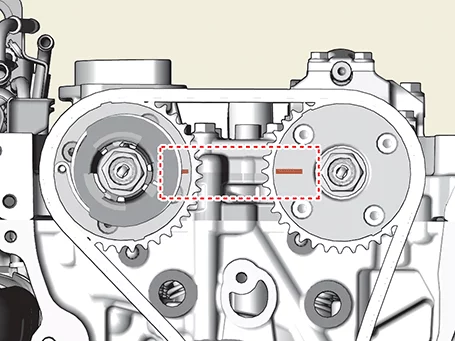
|
| 11.
|
Install the timing chain cover.
(Refer to Timing System - "Timing Chain Cover")
|
| 12.
|
Install in reverse order of removal.
|
| 13.
|
Fill the engine with oil.
(Refer to Lubrication System - "Engine Oil")
|
| 14.
|
Start engine and check for any leaks.
|
Timing Chain Inspection
| Sprocket, timing chain tensioner, timing chain guide, timing chain
tensioner arm |
| 1.
|
Check the CVVT sprocket, crankshaft sprocket teeth for abnormal wear, cracks or damage. Replace
if
necessary.
|
| 2.
|
Check a contact surface of the chain tensioner arm and guide for abnormal wear, cracks or
damage,Replace
if necessary.
|
| 3.
|
Check that the chain tensioner piston slides smoothly and inspect whether the ratchet operates
normally.
Replace if necessary.
|