Contents:
Air Cleaner Filter Replacement
| 1.
|
Remove the air cleaner filter.
|
| 2.
|
Check if the air filter is excessively dirty. If so, replace the air cleaner filter.
|
| 3.
|
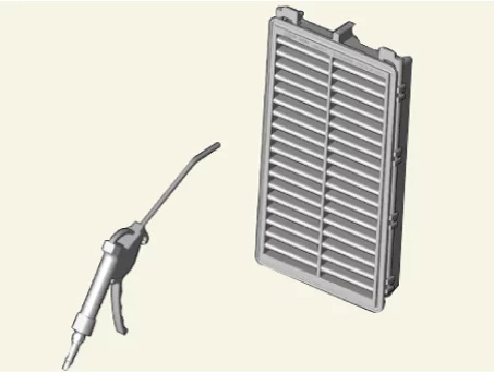
If the air cleaner filter needs to be cleaned, blow compressed air as shown in the illustration
to clean
it.
|
Be fully aware of the direction of using compressed air on the air cleaner.
|
|
| 4.
|
Reinstall the air cleaner filter.
|
| Air Cleaner Filter Replacement |
| 1.
|
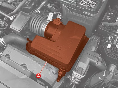
Pull the clamp to open the air cleaner cover (A).
|
| 2.
|
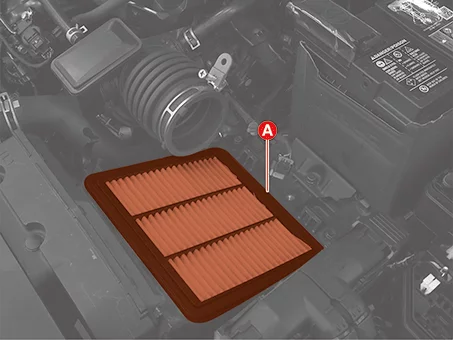
Replace the air cleaner filter (A) with a new one.
|
•
|
If there are foreign substances inside the air cleaner
assembly, wipe the inside of the
air cleaner assembly and then replace the air cleaner filter.
|
|
•
|
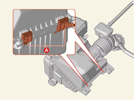
Insert the hinge (A) and engage the clamp when mounting the air
cleaner cover.
|
|
|
| 1.
|
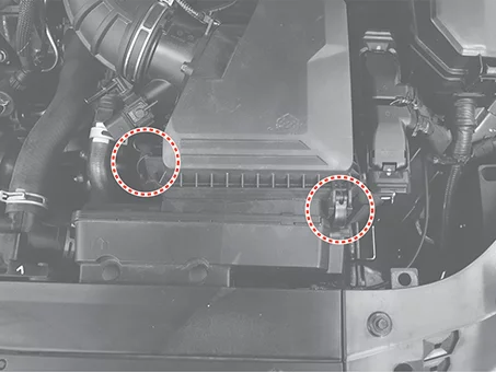
Open the air cleaner filter cover after releasing the clips.
|
| 2.
|
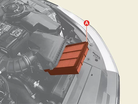
Replace the air cleaner filter (A) with a new one.
|
If there are foreign matters inside the air cleaner assembly, replace the
filter after cleaning
the inside.
|
|
Battery Inspection
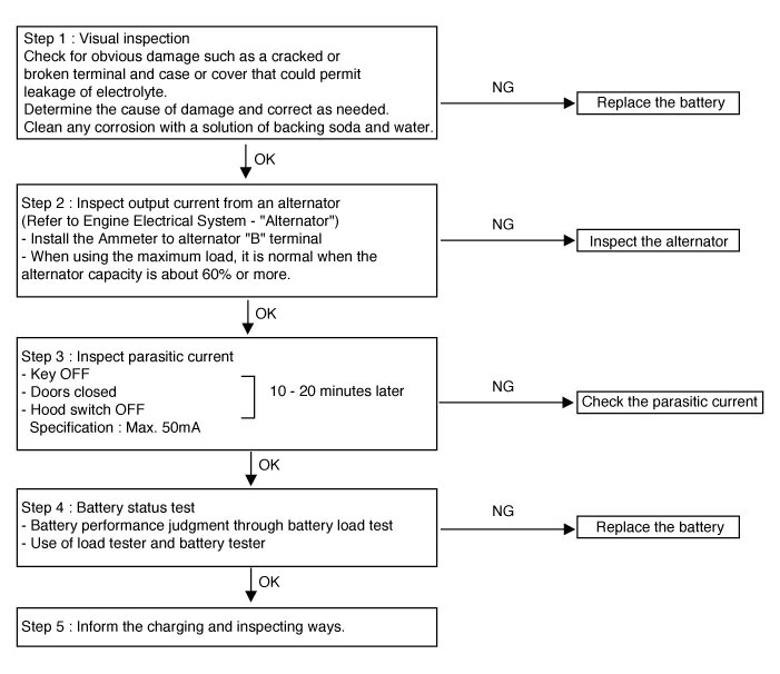
Battery visual and basic inspection
| 1.
|
Check the battery terminal corrosion and connection.
|
| 2.
|
Check the battery leakage or swelling.
|
| 3.
|
Check the case for damage.
|
Alternator Charging Current Inspection
| 1.
|
Check the alternator charging current.
(Refer to Charging System - "Alternator")
|
Vehicle Parasitic Current Inspection
[Using an Ammeter]
| 1.
|
Turn all electric devices OFF, and then turn the IG OFF.
|
| 2.
|
Close all doors except the engine hood, and then lock all doors.
|
–
|
Disconnect the connector from the hood switch to prevent it from being
operated.
|
|
| 3.
|
Wait until the main system of the vehicle becomes sleep mode.
|
For an accurate measurement of a vehicle parasitic current, all electrical
systems should go to
sleep mode. (It takes at least one hour or at most one day.) However, an
approximate vehicle
parasitic current can be measured after 10 - 20 minutes.
|
|
| 4.
|
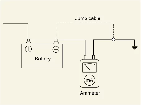
Connect an ammeter between the battery negative ( - ) terminal and the negative ( - ) cable
terminal, and
then disconnect the battery cable ( - ) terminal slowly.
|
•
|
Be careful not to let the lead wire of the ammeter come off the
battery terminal and the
cable so that the battery is not initialized.
|
|
•
|
If the battery is initialized due to disconnection of lead wire
of ammeter from the
battery cable or terminal, reconnect the battery and start the
engine, or measure from the
first step after the IG is on for more than 10 seconds.
|
|
•
|
To prevent battery initialization in advance, follow the
procedure below.
|
| 1) |
Connect the jumper cable between the battery ( - ) terminal and
the cable ( - ) terminal
first.
|
| 2) |
Disconnect the negative ( - ) battery terminal.
|
| 3) |
Connect the ammeter in parallel to the jumper cable.
|
| 4) |
Disconnect the jumper cable and check the parasitic current
value of the ammeter.
|
|
|
| 5.
|
Check the parasitic current value of the ammeter.
|
Limit value (mA) : Below 50 (after 10 -
20 min.)
|
|
•
|
If the parasitic current exceeds the limit value, remove the fuse one by one
and measure it to
find the problem circuit.
|
|
•
|
Re-measure the parasitic current and find the problem unit by removing the
units connected to the
problem circuit one by one.
|
|
[Using the Clamp Type Ammeter]
| 1.
|
Turn all electric devices OFF, and then turn the IG OFF.
|
| 2.
|
Close all doors except the engine hood, and then lock all doors.
|
–
|
Disconnect the connector from the hood switch to prevent it from being
operated.
|
|
| 3.
|
Wait until the main system of the vehicle becomes sleep mode.
|
For an accurate measurement of a vehicle parasitic current, all electrical
systems should go to
sleep mode. (It takes at least one hour or at most one day.) However, an
approximate vehicle
parasitic current can be measured after 10 - 20 minutes.
|
|
| 4.
|
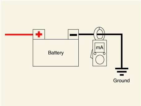
Install the clamp type ammeter on battery negative ( - ) terminal
|
•
|
When using a clamp type ammeter, use an ammeter that can
measure mA. If not, it is
difficult to measure the correct parasitic current.
|
|
•
|
When ( - ) sign appears on the ammeter of the clamp type,
install the ammeter in the
opposite direction.
|
|
|
| 5.
|
Check the parasitic current value of the ammeter.
|
Limit value (mA) : Below 50 (after 10 -
20 min.)
|
|
•
|
If the parasitic current exceeds the limit value, remove the fuse one by one
and measure it to
find the problem circuit.
|
|
•
|
Re-measure the parasitic current and find the problem unit by removing the
units connected to the
problem circuit one by one.
|
|
Battery Performance Inspection
| 1.
|
Measure the performance of the battery by using the battery tester and battery load tester.
|
•
|
Check that the battery positive ( + ) and negative ( - )
terminals are properly
connected.
|
|
•
|
Do not disconnect the battery while the engine is running.
|
|
|
Battery Voltage Inspection
| 1.
|
If it is within 20 minutes since the engine is stopped, turn on the ignition switch and operate
the
electric devices (headlamp, blower motor, rear defogger) for 60 seconds to get rid of residual
voltage.
|
| 3.
|
Measure the voltage between the negative ( - ) terminal and battery positive ( + ) terminal of
the
battery.
|
Specified voltage (V) : approximately
12.7 - 12.9 [25°C
(77°F)]
|
|
| 4.
|
If the measured value is below the specified voltage, charge the battery.
|
Drive Belt Removal and Installation
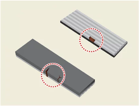
Visually check the belt for excessive wear, frayed cords etc.
If any defect has been found, replace the drive belt.
| 1.
|
Remove the engine room under cover.
(Refer to Engine and Transaxle Assembly - "Engine Room Under
Cover")
|
| 2.
|
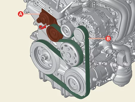
For release the tension, turn the drive belt tensioner (A) counterclockwise then remove the
drive belt
(B).
|
| 3.
|
Install in the reverse order of removal.
|
There are two ways to remove the drive belt.
| [When removing the drive belt from the upper of the
vehicle] |
| 1.
|
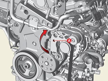
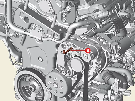
After installing the wrench in the drive belt tensioner maintenance hole (A), turn it
clockwise.
|
•
|
After turning the drive belt tensioner clockwise, install the
retaining pin (A) to secure
the drive belt tensioner.
|
|
•
|
For the fixing pin, use a 6mm hexagon wrench or a pin with the
same outer diameter as a
6mm hexagon wrench.
|
|
|
| 2.
|
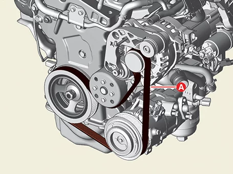
Remove the drive belt (A).
|
When removing the drive belt, remove the drive belt from the water pump pulley.
|
|
| 3.
|
Install in reverse order of removal.
|
When installing the drive belt, make the drive belt into a larger circular ring
shape than the
alternator pulley as shown in the figure below, and then install the alternator
→ air conditioner
compressor → crankshaft damper pulley → water pump → drive belt tensioner.

|
|
| [When removing the drive belt from the Lower of the
vehicle] |
| 1.
|
Remove the engine compartment under cover.
(Refer to Engine and Transaxle Assembly - "Engine Room Under
Cover")
|
| 2.
|
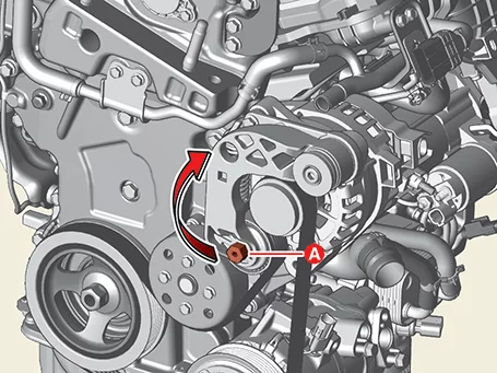
Install the spanner on the drive belt tensioner arm boss (A) and turn it clockwise.
|
•
|
After turning the drive belt tensioner clockwise, install the
retaining pin (A) to secure
the drive belt tensioner.
|
|
•
|
For the fixing pin, use a 6mm hexagon wrench or a pin with the
same outer diameter as a
6mm hexagon wrench.
|
|
|
| 3.
|
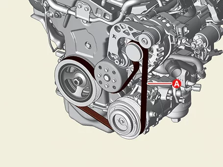
Remove the drive belt (A).
|
When removing the drive belt, remove the drive belt from the water pump pulley.
|
|
| 4.
|
Install in reverse order of removal.
|
When installing the drive belt, make the drive belt into a larger circular ring
shape than the
alternator pulley as shown in the figure below, and then install the alternator
→ air conditioner
compressor → crankshaft damper pulley → water pump → drive belt tensioner.
|
|
Exhaust System Inspection
| 1.
|
Visually check the pipes, hangers and connections for severe corrosion, leaks or damage.
|
| 2.
|
Check for unusual exhaust sounds or abnormal exhaust fumes.
|
Fuel Lines, Hoses and Connections Inspection
Visually check the fuel lines for cracks, leakage, loose connections, deformation or tank band looseness.
Spark Plug [Gasoline Only] Removal and Installation
| 1.
|
Remove the ignition coil.
(Refer to Engine Electrical System - "Ignition Coil")
|
| 2.
|
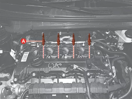
Remove the spark plug (A) by using a spark plug socket.
|
Tightening torque :
14.7 - 24.5 N·m (1.5 - 2.5 kgf·m, 10.8 - 18.1 lb·ft)
|
|
Be careful not to get foreign matter into the spark plug hole.
|
|
| 1.
|
Install in the reverse order of removal.
|
•
|
Install the spark plug to the specified torque.
|
|
•
|
Be careful not to damage the electrode when installing the
spark plug.
|
|
•
|
If the spark plug is dropped, it may cause internal damage. (Do
not reuse)
|
|
•
|
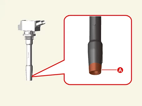
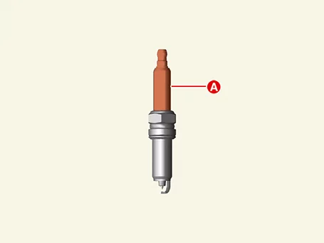
When installing the parts, use cloth to clean the contaminated
area (A).
- Use a clean and soft cloth to avoid damage.
(When replacing ignition coil and spark plug together, cleaning
is not required.)
|
|
|
Spark Plug [Gasoline Only] Inspection
| 1.
|
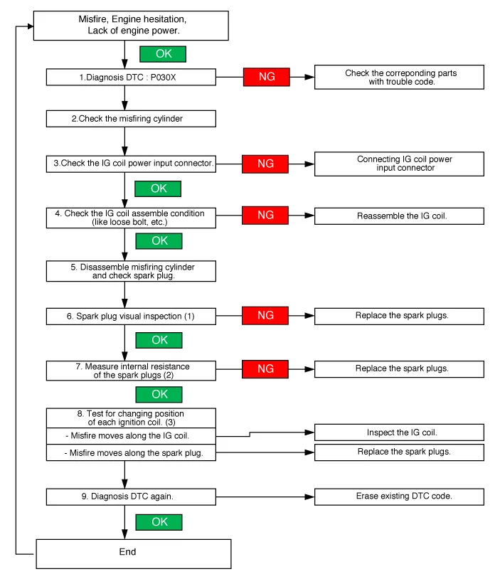
Check the DTC code by using the KDS (Refer to "DTC guide").
|
| 2.
|
Check the ignition coils.
(Refer to Ignition System - "Ignition Coil")
| (1)
|
Check the ignition coil connector.
|
| (2)
|
Check the ignition coil installation state.
|
Tightening torque :
9.8 - 11.8 N·m (1.0 - 1.2 kgf·m, 7.2 - 8.7 lb·ft)
|
|
|
| 3.
|
Remove the spark plug.
(Refer to Engine Electrical System - "Spark Plug")
|
| 4.
|
Visually inspect the external spark plugs.
|
Spark plug gap [mm (in.)] : 1.0 - 1.1
(0.0394 - 0.0433)
|
Symptom
|
Suspected Cause
|
Correction
|
|
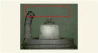
Melting Electrode
|
Abnormal Combustion, Overheat
|
Replace the Spark Plug
|
|
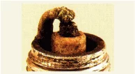
Carbon and Foreign Matter
|
|
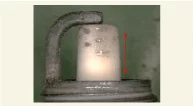
Ring Crack
|
Abnormal Combustion, External Shock
|
|
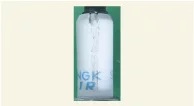
Vertical Crack
|
External Shock
|
|
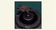
Overheat
|
Abnormal Combustion
|
Symptom
|
Suspected Cause
|
Correction
|
|
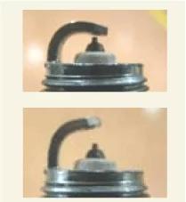
Poor Gap
|
Physical Damage
|
Replace the Spark Plug
|
|

Flash Over
|
Excessive Electrode Wear
|
Replace the Spark Plug, Ignition Coil
|
|
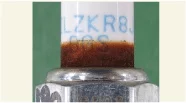
Corrosion/Rust
|
Remaining Oil Mist
|
Reassemble the Spark Plug
|
|
| 5.
|
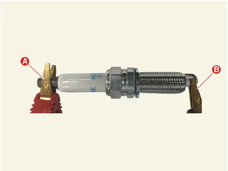
Check the resistance between the spark plugs terminal (A) and probe (B) by using a multi-tester
or a
resistance meter.
|
Specified value (kΩ) : 2 - 20
|
|
•
|
Avoid the contact resistance between probe and spark plugs
(when it occurs, the measured
value is not stabilized).
|
|
•
|
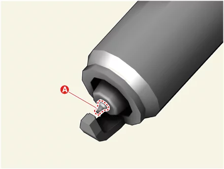
Be careful not to damage center electrode (A) while measuring
resistance.
|
|
|
| 6.
|
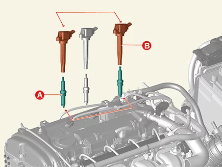
Test for changing position of each ignition coil and spark plug.
| 1) |
Remove the spark plug (A) and ignition coil (B) from the misfiring cylinder and
exchange them
with one of the other cylinders.
(Refer to Engine Electrical System - "Spark
Plug")
|
| 2) |
Replace the spark plugs, if misfire moves along the spark plugs.
|
|
Vapor Hose and Fuel Filler Cap Inspection
|
•
|
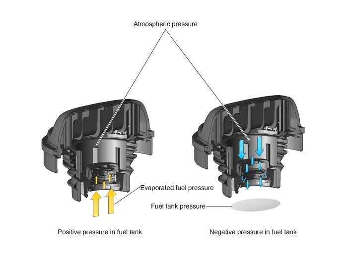
The fuel filler cap works as a check valve, allowing fluid to flow in only one direction.
|
|
•
|
When the inside of the fuel tank reaches a vacuum state outside air enters to release the
vacuum, and the
evaporative fuel gas inside the fuel tank is prevented from escaping into the atmosphere.
|
Intelligent Variable Transmission (IVT) Fluid Inspection
| Inspect the Intelligent Variable Transmission Fluid (IVTF)
level
|
|
When checking the IVTF level, be careful not to allow foreign substance (like dust) to enter
through the
filler hole.
|
| 1.
|
Remove the air cleaner assembly.
(Refer to Engine Mechanical System - "Air Cleaner")
|
| 2.
|
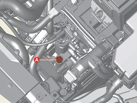
Remove the IVTF filler plug (A).
|
| 3.
|
Start the engine to warm up the IVTF.
|
Do not step on the brake and accelerator simultaneously to warm up the IVTF.
|
|
| 4.
|
Check by using KDS that the temperature of the IVTF is between 45 - 55°C (113 - 131°F).
|
| 5.
|
Move the shift lever slowly from "P" to "D", then back to "P". Repeat this sequence two times
and then
move the shift lever to "P" range.
|
Pause in each range for more than 2 seconds.
|
|
| 6.
|
Remove the engine room under cover.
(Refer to Engine Mechanical System - "Engine Room Under
Cover")
|
| 7.
|
Lift the vehicle and remove the IVTF level plug (A).
|
When removing the IVTF level plug, keep the vehicle on a level ground.
|
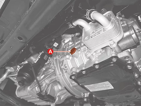
|
| 8.
|
Check the IVTF level.
|
Normal : 0.15 - 0.45 liters of IVTF
flows out for 2
minutes
Excessive (abnormal) : Over 0.45 liters
of IVTF flows out
for 2 minutes
Insufficient (abnormal) : Below 0.15
liters of IVTF flows
out for 2 minutes
|
If the IVTF level is too high or low, follow the instructions below.
|
•
|
Excessive : Drain until the IVTF flows out in a thin oil
stream.
|
|
•
|
Insufficient : Add until the IVTF flows out in a thin oil
stream.
|
|
|
| 9.
|
Install the IVTF level plug (A).
|
Tightening torque :
34.3 - 44.1 N·m (3.5 - 4.5 kgf·m, 25.3 - 32.5 lb·ft)
|
|
The existing IVTF level plug gasket (A) must be replaced with a new one (do not
reuse).
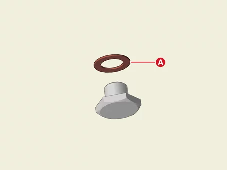
|
|
| 10.
|
Lower the vehicle and add the 0.3 liters (amount of oil drained during inspection) of SP-CVT1
through the
IVTF filler hole.
|
•
|
Be sure to use the genuine IVT Fluid (SP-CVT1)
|
|
•
|
When replacing with non-genuine IVT fluid, bad shift and
vibration may occur, causing
damamge to the IVT.
|
|
•
|
Non-genuine IVT fluid includes after market IVT fluid indicated
as interchangeable with
genuine Kia fluid.
|
|
|
| 11.
|
Install the IVTF filler plug (A).
|
Tightening torque :
34.3 - 44.1 N·m (3.5 - 4.5 kgf·m, 25.3 - 32.5 lb·ft)
|
|
The existing IVTF filler plug gasket (A) must be replaced with a new one (do
not reuse).
|
|
Automatic Transaxle Fluid Inspection
Inspect the Automatic Transaxle Fluid (ATF) level
|
When checking the ATF level, be careful not to allow foreign substance (like dust) to enter
through the
filler hole.
|
| 1.
|
Remove the air cleaner assembly.
(Refer to Engine Mechanical System - "Air Cleaner")
|
| 2.
|
Add 0.7 ℓ of ATF SP4M-1 through the ATF filler hole after removing the eyebolt (A).
|
Recommended : ATF SP4M-1
The list of automatic transaxle fluid approved
by Kia : SK
ATF SP4M-1, MICHANG ATF SP4M-1, S-OIL ATF SP4M-1, Kia Genuine ATF SP4M-1
|
|
•
|
If the genuine oil that is developed for best performance is
not used, it may cause
performance or problems with transaxle.
|
|
•
|
The use of non-specified oil could even result in shift quality
deterioration and
vibrations, eventually, transaxle failure.
|
|
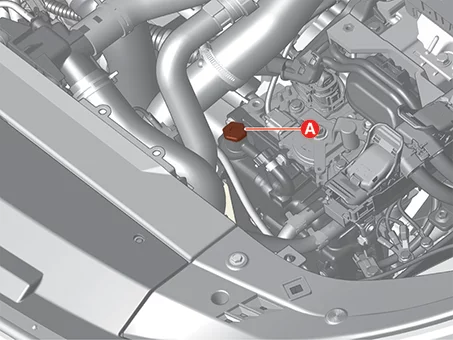
|
| 3.
|
Start the engine to warm up the ATF.
|
Do not step on the brake and accelerator simultaneously to warm up the ATF.
|
|
| 4.
|
Check using KDS that the temperature of the ATF is between 50 - 60°C (122 - 140°F).
|
| 5.
|
Move the shift lever slowly from "P" to "D", then back to "P". Repeat this sequence two times
and then
move the shift lever to "P" range.
|
Pause in each range for more than 2 seconds.
|
|
| 6.
|
Remove the ATF level plug (A).
|
When removing the ATF level plug, keep the vehicle on a level ground.
|
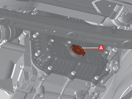
|
| 7.
|
Check the ATF level.
|
Normal : ATF flows out in a thin oil
stream.
Excessive : Over 0.9 liters of ATF flows
out for 2
minutes.
Insufficient : There is no fluid flow.
|
If the ATF level is too high or low, follow the
instructions
below.
|
•
|
Excessive : Drain until the ATF flows out in a thin oil stream.
|
|
•
|
Insufficient : Add until the ATF flows out in a thin oil
stream.
|
|
|
| 8.
|
Install the ATF level plug (A).
|
| 9.
|
Lower the vehicle and install the ATF eyebolt (A).
|
Tightening torque :
4.9 - 5.9 N·m (0.5 - 0.6 kgf·m, 3.6 - 4.3 lb·ft, 43.4 - 52.1 lb·in)
|
|
| 10.
|
Install the air cleaner assembly.
(Refer to Engine Mechanical System - "Air Cleaner")
|
Other information:
Kia K4 (CL4) 2025-2026 Service Manual: Smart Cruise Control display and control
You can conveniently monitor the current status and operational state of the Smart Cruise Control (SCC) system by navigating to the "Driving Assist" view on your Kia K4 instrument cluster. For further details on customizing these views, please refer to your owner's manual section on LCD display modes.
The Kia K4 instrument cluster provides clear visual feedback regarding the SCC status through various indicators:
When the system is active and operating:
Shows whether a lead vehicle is detected ahead and highlights the current vehicle-to-vehicle distance level setting.
Kia K4 (CL4) 2025-2026 Service Manual: Battery On Vehicle Inspection
On Vehicle Inspection
Battery Visual and Basic Inspection
1.
Check the battery terminal corrosion and connection.
2.
Check the battery leakage or swelling.
3.